Product
 Brand
Brand Articles
 Tools
Tools
Crystal Oscillators Explained: How They Work and How to Specify One
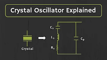
Crystal Oscillator Explained
A crystal oscillator is the timekeeper behind almost every digital system you touch. The microcontroller that runs your firmware, the radio that meets a tight channel spacing, the camera that timestamps a frame - all of them lean on a small slice of quartz vibrating at a remarkably steady rate. For an embedded or hardware engineer, the hard part is rarely understanding that quartz vibrates. The hard part is turning that physics into a clocking choice you can defend: which part to place, what to ask the supplier for, and how the numbers on the datasheet add up over temperature and years of service.
How a quartz crystal produces a stable frequency
Quartz is piezoelectric: squeeze it and a tiny voltage appears across the material, apply a voltage and it physically deforms. When you cut quartz into a thin plate and plate electrodes onto it, that coupling lets an electrical signal set the plate vibrating mechanically, and the mechanical vibration in turn reinforces the electrical signal. The plate has a mechanical resonance set mainly by its dimensions and the angle at which it was cut from the raw crystal, and that resonance is extraordinarily sharp. The sharpness is what makes quartz so useful: the material strongly prefers one frequency and resists being pushed away from it.
Electrically, a crystal behaves like the equivalent circuit that timing manufacturers print on their datasheets - a series branch of motional inductance, motional capacitance, and a small series resistance, all sitting in parallel with a shunt capacitance formed by the electrodes and package. That model is worth internalising because it explains the two resonances every crystal has. The series branch creates a series-resonant frequency where impedance dips low, and the interaction with the shunt capacitance creates a slightly higher parallel-resonant frequency where impedance peaks. The two are close together, but a circuit deliberately operates at one or the other, and that choice changes how you specify the part.
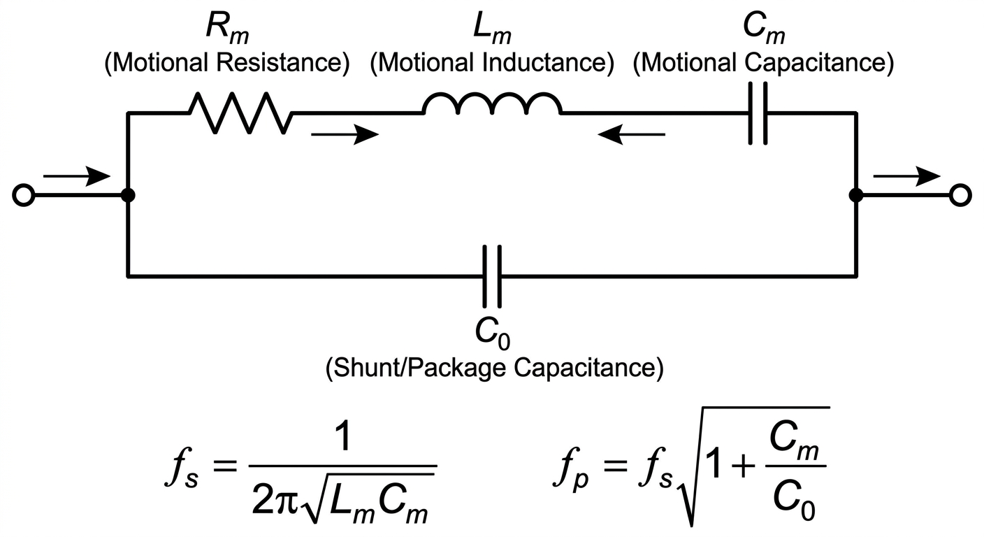
Figure 1: The Butterworth-Van Dyke (BVD) equivalent circuit model of a quartz crystal, showing the motional parameters ($R_m$, $L_m$, $C_m$) in parallel with the shunt package capacitance ($C_0$).
A bare crystal is a passive component. On its own it does nothing - it needs an amplifier and the right feedback to start and sustain oscillation. In a typical microcontroller, that amplifier is the inverter built into the on-chip oscillator block, and the crystal plus two external capacitors closes the loop. The crystal sets the frequency with great precision; the surrounding circuit supplies the energy that keeps the vibration alive.
Crystal versus packaged oscillator: choosing the right building block
There are two distinct things people loosely call "the crystal," and confusing them is one of the most common early mistakes.
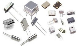
A crystal, or quartz resonator, is the passive piece of quartz in a package with two terminals. It cannot oscillate by itself. You pair it with the oscillator circuit inside a microcontroller, a PLL, or a transceiver, and you are responsible for the load capacitors and the layout that make that loop behave.
A crystal oscillator module, often shortened to XO, is a self-contained part that includes the resonator and the sustaining circuit in one package. It has a power pin and a clock output pin, and it simply produces a running clock when you power it. You give up the chance to tune the loop yourself, but you gain a guaranteed output and a much simpler board.
The decision usually comes down to where the oscillator circuit already lives. If your main chip has a competent on-chip oscillator and you can manage the layout, a bare crystal is smaller and cheaper. If you need a clock for a device that has no oscillator input, if you want to remove loop tuning from your list of risks, or if you need a tightly controlled output the moment power is applied, a packaged oscillator earns its place. The table below summarises the trade.
| Consideration | Bare crystal (resonator) | Packaged oscillator (XO module) |
|---|---|---|
| What is inside | Quartz resonator only | Resonator plus sustaining amplifier |
| External parts needed | Load capacitors, sometimes a feedback resistor | Usually a decoupling capacitor only |
| Who tunes the loop | You, through load capacitors and layout | The manufacturer, internally |
| Output | None until paired with a circuit | A ready clock signal on a dedicated pin |
| Typical use | Microcontroller, PLL, or transceiver reference | Standalone clock for logic, FPGA, or a chip with no oscillator input |
| Main risk you own | Start-up margin and load-capacitance match | Selecting the right output type and supply |
Series versus parallel resonance and load capacitance
Because a crystal has both a series and a parallel resonance, a datasheet always tells you which mode the part is specified for, and the two are not interchangeable. A series-mode crystal is meant to be driven where its impedance is lowest, and its frequency is defined without any external capacitance assumption. A parallel-mode crystal is the more common choice in microcontroller and clock circuits, and here the subtlety appears: a parallel-mode part is only on frequency when the circuit presents a specific load capacitance to it.
Load capacitance is the total capacitance the crystal "sees" looking back into the rest of the circuit. The manufacturer chooses a target load capacitance, trims the crystal to be on frequency at exactly that value, and prints it on the datasheet. Your job is to make the real circuit present that same capacitance. In a classic two-capacitor configuration the two external load capacitors appear in series to the crystal, and you must add the board and pin parasitic capacitance - usually called stray capacitance - that sits alongside them. The practical formula manufacturers publish relates the external capacitor values, the series combination, and the stray capacitance to the specified load; the exact target value is part-specific, so read it from the datasheet you intend to buy.
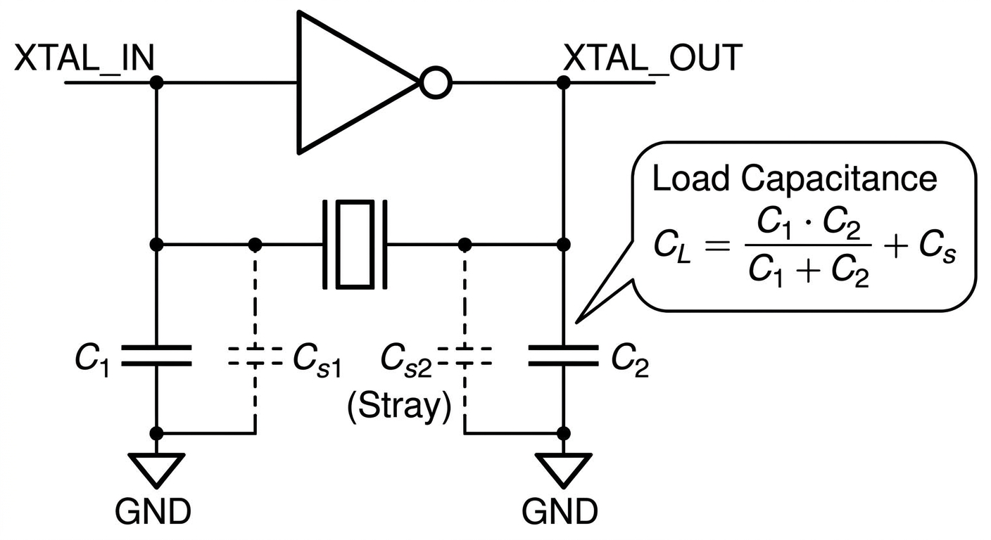
Figure 2: A typical Pierce oscillator circuit configuration where the total load capacitance ($C_L$) seen by the parallel-mode crystal is a combination of external capacitors ($C_1$, $C_2$) and stray PCB layout capacitance ($C_s$).
Two things follow from this. First, if you present too much or too little capacitance, the part runs slightly fast or slow, and the error shows up as a fixed frequency offset that no amount of stability rating will hide. Second, stray capacitance is real and varies with layout, so a careful designer accounts for it rather than assuming the two named capacitors are the whole story. Keeping the crystal close to its pins, with short symmetrical traces and a clean ground reference, is what keeps the load you designed equal to the load the part actually experiences.
The specifications that define a crystal oscillator
When you read a crystal or oscillator datasheet, a handful of parameters do almost all the work. The single most useful habit is to stop treating them as separate line items and instead combine the frequency-error terms into one budget that has to hold over the full temperature range and the full service life of the product.
Nominal frequency is the rated frequency the part is designed around. It is the headline number and the starting point for everything else.
Frequency tolerance is the initial error at a reference temperature, straight from the factory. It captures manufacturing spread.
Frequency stability over temperature is how far the frequency wanders as the part heats and cools across its rated range. This is usually the dominant term in an environment that is not temperature controlled.
Aging is the slow drift over months and years as the quartz and mounting settle. It is small per year but accumulates over a long-lived product.
Load capacitance, as above, sets the on-frequency condition for a parallel-mode part and quietly adds a fixed offset if you get it wrong.
Drive level is how much power the circuit pushes into the crystal. Too much can stress or age the part; too little can leave it unable to start reliably.
The frequency budget is simply the sum of the error terms that apply to your worst case. Initial tolerance, temperature stability, aging over the design life, and any offset from load-capacitance error all add up, and the total has to stay inside whatever your system demands - the channel spacing of a radio, the lock range of a PLL, the timekeeping accuracy of a clock. Working it this way prevents the trap of buying a part with an impressive stability figure while ignoring an aging term or a load mismatch that eats the whole margin.
| Specification | What it describes | Why it matters in selection |
|---|---|---|
| Nominal frequency | The rated operating frequency | Must match what the receiving circuit expects |
| Frequency tolerance | Initial error at a reference temperature | Sets the starting point of the budget |
| Stability over temperature | Drift across the rated temperature range | Often the largest single contributor |
| Aging | Slow drift over the product life | Accumulates; matters for long-service designs |
| Load capacitance | Capacitance the circuit must present (parallel mode) | A mismatch adds a fixed frequency offset |
| Drive level | Power delivered into the crystal | Affects start-up reliability and long-term health |
Treat the actual figures behind each row as part-specific. A named manufacturer datasheet will state them for the exact ordering code, and that is the number you should design to rather than any general rule of thumb.
Oscillator families: XO, TCXO, VCXO, OCXO, and MEMS
Packaged oscillators come in families that trade stability against cost, power, size, and warm-up behaviour. Understanding the ladder helps you avoid both over-specifying a part you do not need and under-specifying one that will fail in the field.
A plain crystal oscillator, the simple XO, gives you a clean clock with the stability of the bare crystal and nothing added. A temperature-compensated oscillator, the TCXO, measures temperature and applies a correction so the frequency holds far better across the range, which suits portable radios and GNSS front ends. A voltage-controlled oscillator, the VCXO, exposes a control voltage that pulls the frequency over a small range, which is what you want when the oscillator has to be steered by a control loop. An oven-controlled oscillator, the OCXO, holds the crystal at a regulated elevated temperature so its environment barely changes, delivering the highest stability at the cost of more power and a warmup period. MEMS oscillators replace the quartz with a micro-machined silicon resonator and an integrated circuit; they trade the traditional quartz pedigree for strong shock resistance, flexible frequencies, and small packages.
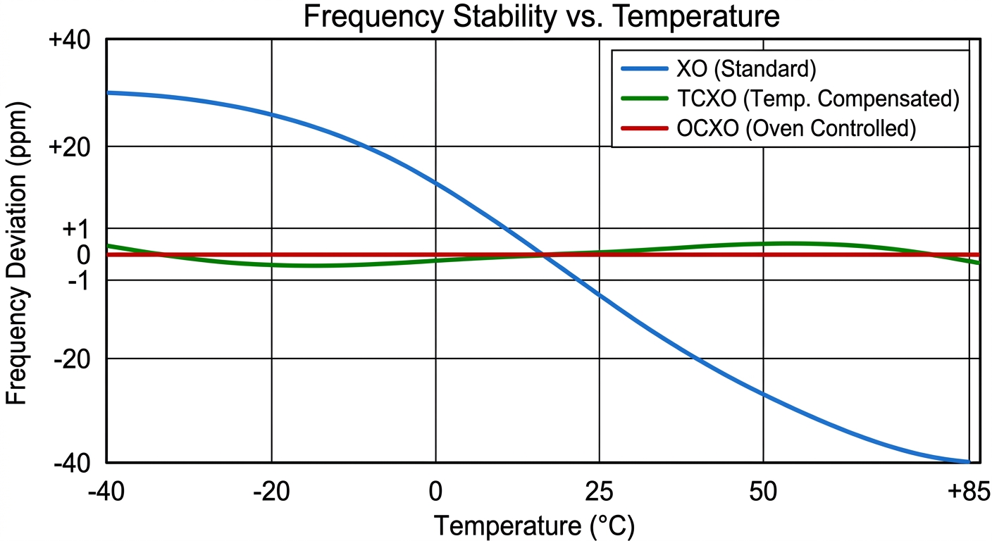
Figure 3: Comparative frequency stability (in ppm) across operating temperature for standard (XO), temperature-compensated (TCXO), and oven-controlled (OCXO) crystal oscillators (indicative curves for qualitative comparison).
| Family | How it controls frequency | Relative stability | Relative power and cost | Typical fit |
|---|---|---|---|---|
| XO (simple oscillator) | Resonator plus sustaining amplifier, no correction | Baseline | Lowest | General logic and reference clocks |
| TCXO | Active temperature compensation | Better over temperature | Moderate | Portable radios, GNSS, handhelds |
| VCXO | External control voltage pulls frequency | Comparable to XO, tunable | Moderate | Loops that must steer the clock |
| OCXO | Crystal held in a temperature-controlled oven | Highest | Highest, needs warm-up | Base stations, instruments, holdover |
| MEMS | Silicon resonator with an integrated circuit | Wide range, configurable | Competitive, very robust | Shock-prone, space-limited, flexible-frequency designs |
The right place on this ladder is set by your frequency budget, not by habit. If a TCXO meets the budget over your temperature range, an OCXO only adds power draw and warm-up complexity you do not need; if a simple XO drifts past your limit on a hot day, no amount of careful layout will rescue it.
Common specification and design mistakes
Most crystal problems trace back to a small set of recurring errors, and all of them are avoidable at the design-review stage.
The first is a mismatched load capacitance on a parallel-mode crystal. The board presents a different capacitance than the datasheet assumed, the frequency lands off target, and the symptom looks like a mysterious fixed offset. The fix is to compute the external capacitors from the specified load, include a realistic estimate of stray capacitance, and confirm the result against the manufacturer's recommendation for that part.
The second is insufficient start-up or drive margin. A crystal needs enough loop gain to begin oscillating reliably across temperature, supply, and unit-to-unit spread, and a circuit that barely starts on the bench can fail to start in the cold or after years of aging. A robust design leaves headroom in the oscillator's gain and respects the drive-level rating so the part starts every time without being over-driven.
The third is over- or under-specifying stability. Paying for an OCXO when a TCXO clears the budget wastes power, board area, and money on warm-up you do not need. Choosing a loose XO when the application needs temperature compensation guarantees field failures that no firmware patch can cure. The frequency budget is the tool that keeps this honest: total the error terms for the real worst case, then buy the least expensive part that fits with margin.
A short pre-purchase checklist captures the same discipline:
| Check before you commit | What to confirm |
|---|---|
| Resonance mode | Series or parallel matches the host circuit |
| Load capacitance | External capacitors plus stray equal the specified load |
| Frequency budget | Tolerance, stability, aging, and offset stay within the system limit |
| Drive and start-up | Loop gain and drive level give reliable cold start with margin |
| Environment | Temperature range, shock, and aging suit the deployment |
| Output and supply | For a module, the output type and voltage match the receiving pin |
Frequently asked questions
How does a crystal oscillator actually keep time so accurately?
A thin plate of quartz has a very sharp mechanical resonance because the material strongly prefers one vibration frequency. The piezoelectric effect couples that mechanical resonance to the electrical circuit, so the surrounding amplifier keeps feeding energy back at exactly the frequency the quartz wants. The result is a clock far steadier than any simple resistor-capacitor or inductor-capacitor circuit can manage.
What is the difference between a crystal and a crystal oscillator?
A crystal is the passive quartz resonator alone; it sets a frequency but produces no signal until it is paired with an oscillator circuit and its load capacitors. A crystal oscillator module packages the resonator together with that sustaining circuit, so it has a supply pin and an output pin and delivers a running clock on its own.
How do I choose between an XO, TCXO, VCXO, and OCXO?
Start from your frequency budget across the full temperature range and service life. A plain XO suits undemanding logic clocks; a TCXO handles tighter accuracy over temperature in portable gear; a VCXO is for clocks that must be steered by a control loop; an OCXO delivers the highest stability where power and warm-up are acceptable. Pick the least costly family that meets the budget with margin.
Why does my crystal run at the wrong frequency even though it is the right part?
The most likely cause is a load-capacitance mismatch on a parallel-mode crystal. If the external capacitors plus the board's stray capacitance do not equal the load the datasheet specifies, the part settles slightly fast or slow as a fixed offset. Recompute the capacitors from the specified load, account for stray capacitance, and verify against the manufacturer's guidance.
Why would a crystal oscillator fail to start at all?
Start-up failure usually means too little loop gain or drive margin, often worsened by cold temperature, a marginal supply, or component spread. The crystal needs enough energy to build up oscillation reliably under the worst conditions, so a sound design leaves gain headroom and keeps the drive level within the rated window rather than at its edge.
Why is 32.768 kHz such a common crystal frequency?
That nominal frequency is a power of two, so a simple chain of digital dividers turns it into a clean one-pulse-per-second tick, which is exactly what a real-time clock needs. Small, low-power tuning-fork crystals at that nominal value are widely available for timekeeping, which is why you see them next to so many microcontrollers and clock chips.
Should I use a MEMS oscillator instead of a quartz one?
A MEMS oscillator can be a strong choice when you need high shock and vibration resistance, an unusual or programmable frequency, or a very small package, since it uses a silicon resonator with an integrated circuit. Quartz remains the familiar reference for many designs, so the decision rests on your environment, the frequency you need, and the stability your budget requires - confirmed against the specific part's documentation.
Sources and references
Abracon timing product datasheets and selection resources walk through the parameters that define crystals and oscillators and show how a manufacturer states load capacitance, tolerance, and stability for a specific ordering code; they describe one supplier's catalogue, so confirm the exact figures for the part you intend to buy rather than generalising across vendors.
SiTime MEMS oscillator documentation explains how silicon MEMS timing parts work and where their shock resistance and frequency flexibility help; because the vendor designs MEMS devices, treat its comparisons with quartz as one informed perspective alongside quartz-maker documentation.
Epson quartz device technical material covers crystal units and oscillator families including TCXO and OCXO, with practical notes on stability and temperature behaviour; the depth is useful but the values are tied to Epson's own parts, so read them as part-specific rather than universal.
Analog Devices application notes on oscillator and clock design describe how to match a crystal to an oscillator circuit and choose load capacitors; they are written around the company's own clock and converter parts, so adapt the circuit guidance to your host chip's oscillator block.
Texas Instruments crystal-selection and oscillator application notes give worked guidance on load-capacitance calculation, drive level, and start-up margin for microcontroller oscillators; they assume TI's on-chip oscillator characteristics, so cross-check the recommendations against your own device's datasheet.
Renesas timing and clock technical documentation covers crystal and oscillator integration with microcontrollers and clock generators; as vendor material it reflects Renesas parts, so use it for method and verify the numbers against the specific component you select.
 UTMEL
UTMEL
We are the professional distributor of electronic components, providing a large variety of products to save you a lot of time, effort, and cost with our efficient self-customized service. careful order preparation fast delivery service
 A Simple Method to Build a Programmable OscillatorUTMEL27 May 20227576
Hello, this is Candy. Nice to meet you. Digital potentiometers (digiPOT) are versatile and can be used for a variety of tasks, including filtering and generating AC signals. However, depending on the application, the frequency must occasionally be able to fluctuate and be altered. Programmable solutions that permit frequency change through the appropriate interface are quite handy and, in some situations, extremely beneficial to the development of such designs. Using digiPOT, this article shows how to make a programmable oscillator in which the oscillation frequency and amplitude may be modified independently of one another.
Read More Introduction to Types of Oscillator CircuitsUTMEL14 January 202617975
The oscillator operates on the theory of the oscillation and it is a mechanical or electronic unit. The periodic difference between the two items is dependent on the variations in the electricity. The oscillations are used in the watches, clocks, metal detectors and in many other applications use the oscillators.
Read More What are Resonators?UTMEL07 January 202618117
A resonator is an electronic component that can generate a resonant frequency. It has the characteristics of stability and good anti-interference performance. Like the low-frequency circuit, the resonator is also the basic component of the radio frequency circuit. It is widely used in filters, oscillators, frequency meters and adjustable In circuits such as amplifiers. The commonly used RF/MW resonators are basically transmission line resonators.
Read More How to Understand the Oscilloscope Bandwidth?UTMEL13 December 202111051
When a user selects an oscilloscope for essential measurements, the oscilloscope's key characteristics are frequently the only criteria used to determine which oscilloscope to employ. An oscilloscope's most essential index parameters are:Bandwidth, Sampling Rate, Record length
Read More Active Electroacoustic Resonator-Silent SpeakerUTMEL10 November 20216087
Hello everyone, I am Rose. Today I will introduce active electroacoustic resonator to you. The only component of this system is a closed-box dynamic speaker. The surface acoustic impedance of the diaphragm is appropriately changed by connecting an active electrical control system to generate an independently tunable sound absorption coefficient, bandwidth, and resonance frequency.
Read More
Subscribe to Utmel !
![10PAK:WW-SDU2-3]() 10PAK:WW-SDU2-3
10PAK:WW-SDU2-3interlight
![10PAK:WW-V1FH-5]() 10PAK:WW-V1FH-5
10PAK:WW-V1FH-5interlight
![10PAK:WW-KT9C-3]() 10PAK:WW-KT9C-3
10PAK:WW-KT9C-3interlight
![4PAK:WW-5C9X-9]() 4PAK:WW-5C9X-9
4PAK:WW-5C9X-9interlight
![10PAK:WW-0JX5-7]() 10PAK:WW-0JX5-7
10PAK:WW-0JX5-7interlight
![10PAK:WW-R5XH-2]() 10PAK:WW-R5XH-2
10PAK:WW-R5XH-2interlight
![10PAK:WX-01CK-6]() 10PAK:WX-01CK-6
10PAK:WX-01CK-6interlight
![10PAK:WW-4JF3-8]() 10PAK:WW-4JF3-8
10PAK:WW-4JF3-8interlight
![10PAK:WW-ZQ9U-7]() 10PAK:WW-ZQ9U-7
10PAK:WW-ZQ9U-7interlight
![2PAK:WW-1TDG-4]() 2PAK:WW-1TDG-4
2PAK:WW-1TDG-4interlight