
 Product
 Brand
Brand Articles
 Tools
Tools
Comparing Bridge Rectifiers and Full Wave Rectifiers for Beginners
Summary: The primary difference between a bridge rectifier and a full-wave rectifier lies in their diode count and transformer requirements. Bridge rectifiers utilize four diodes without needing a center-tapped transformer, making them highly efficient and cost-effective for modern 2026 electronics projects. Both designs significantly outperform half-wave rectifiers by converting both halves of the AC signal into a stable DC output.
The main difference between a bridge rectifier and a full wave rectifier comes from their design and efficiency. Bridge rectifiers use four diodes, while a full wave rectifier often uses two diodes with a center-tapped transformer. For beginners, bridge rectifiers offer a straightforward setup. Understanding rectifier types helps increase circuit efficiency. Full wave rectifiers deliver about twice the efficiency of half-wave types, which only reach 40.5%. Higher efficiency means better AC to DC conversion, making rectifiers vital in beginner electronics projects.
What Is a Rectifier and How Does It Work?
How Do You Define a Rectifier?
A rectifier is an electronic device that converts an alternating current (AC) signal into a direct current (DC) signal. In simple terms, it takes the alternating current (AC) from a power source and converts it into direct current (DC) that electronic devices can use. Most household electronics, like chargers and radios, need DC to work properly. The rectifier acts as a bridge between the power supply and the device, making sure the energy flows in only one direction. This process helps protect sensitive components and ensures steady operation.
There are different types of rectifiers, but they all share the same goal: turning an ac signal into dc signal. Some use just one diode, while others use several diodes arranged in special ways. The most common types include half-wave, full-wave, and bridge rectifiers. Each type has its own advantages and is chosen based on the needs of the circuit.
Why Are Rectifiers Important in Modern Electronics?
Rectifiers are essential because they provide the steady DC power required by most modern electronic devices to function safely and efficiently. Without a rectifier, 95% of consumer electronics would fail to operate on standard AC grid power. The demand for reliable rectifiers continues to grow as more industries rely on electronic systems. Market reports show that the global regulator rectifier market reached USD 4.87 billion in 2025 and is projected to hit USD 5.36 billion in 2026, growing to USD 14.08 billion by 2035 at an 11.2% CAGR. This 11.2% growth comes directly from the rapid expansion of electric vehicles, renewable energy grids, and advanced consumer electronics.
| Segment | Value (USD Billion) |
|---|---|
| Global Regulator Rectifier Market 2025 | 4.87 |
| Projected Market Size 2026 | 5.36 |
| Projected Market Size 2035 | 14.08 |
| Motor Control Application 2035 Share | 47% |
| Food & Beverages Sector 2035 Share | 48% |
| North America Market Share 2035 | 43% |
Rectifiers also help improve energy efficiency and power quality. New technologies, such as silicon carbide and gallium nitride, make rectifiers more reliable and efficient. Industries use rectifiers to reduce energy waste and keep equipment running smoothly. Statistical methods like MIL-HDBK-217F and FIDES help engineers predict how long a rectifier will last, showing how important these devices are for safe and effective power conversion.
Understanding Bridge Rectifiers
What Is a Bridge Rectifier?
A bridge rectifier is a power conversion circuit that uses four diodes arranged in a bridge configuration to convert AC into DC. They use four diodes arranged in a special pattern called a bridge. This design allows the rectifier to use both halves of the AC signal, making it more efficient than a half-wave rectifier. Recent guides and studies show that the diode bridge rectifier is the most common choice for beginners. It does not need a center-tapped transformer, which keeps the design simple and affordable. Many beginner electronics kits and tutorials use bridge rectifiers because they are easy to build and reliable.
| Configuration | Components Used | Efficiency | Complexity | Typical Use in Beginner Projects |
|---|---|---|---|---|
| Diode Bridge Rectifier | Four diodes arranged in a bridge | More efficient | Simpler | Most common due to simplicity and component availability |
| Center-Tapped Full-Wave Rectifier | Two diodes and center-tapped transformer | Less efficient | More complex | Less common due to complexity and transformer requirement |
How Does a Bridge Rectifier Work?
A bridge rectifier works by directing the flow of electricity through its four diodes, ensuring that current always flows in the same direction through the load. The operational process follows these specific steps:
When AC voltage enters the circuit, two diodes conduct during the positive half-cycle.
The remaining two diodes conduct during the negative half-cycle.
This continuous process ensures that current always flows in a single, unified direction through the load.
The result is a steady, reliable DC output that utilizes the entire AC waveform for maximum efficiency.
However, the voltage drops slightly because the current passes through two silicon diodes simultaneously.
This combined drop is approximately 1.4 volts, which generates thermal energy and may require a heat sink in high-power 2026 applications.
Tip: Bridge rectifiers do not need a center-tapped transformer, which makes them easier to use in many beginner projects.
What Are the Common Uses of Bridge Rectifiers?
Bridge rectifiers are commonly used in power adapters, battery chargers, and small household appliances to convert wall AC into usable DC. They power adapters for phones and laptops, battery chargers, and small appliances. Many beginner electronics projects use bridge rectifiers to convert AC from a wall outlet into DC for circuits. These rectifiers also work well in power supplies for radios, LED lighting, and hobby kits. Their simple design and reliable performance make bridge rectifiers a popular choice for a wide range of applications.
Understanding Full Wave Rectifiers
What Is a Full-Wave Rectifier?
A full-wave rectifier is a circuit that converts both the positive and negative halves of an AC signal into a steady DC output. The core characteristics of this circuit include:
It utilizes either two diodes paired with a center-tapped transformer or four diodes arranged in a bridge configuration.
The primary objective is to generate a higher average DC output voltage while significantly reducing ripple compared to a standard 40.5% efficient half-wave rectifier.
Recent 2026 industry research confirms that a full-wave rectifier delivers approximately 0.637 times the peak voltage as its baseline DC output.
For example, if the AC input features a 10 V peak, the resulting DC output after standard diode drops is approximately 9.3 V.
Engineers typically integrate smoothing capacitors into the circuit to make the DC output even more stable by filtering out residual voltage ripple.
How Does a Full-Wave Rectifier Work?
A full-wave rectifier works by utilizing both halves of the AC cycle, alternating conduction between two sets of diodes to maintain a unidirectional current flow. The operational mechanics include:
During the positive half of the cycle, the first set of diodes conducts, driving current through the load in a specific direction.
During the negative half, the second set of diodes takes over, ensuring the current continues flowing in that exact same direction.
This alternating process effectively doubles the frequency of the DC output ripple, making it significantly easier to filter and smooth with capacitors.
Key performance metrics include the peak inverse voltage (PIV), representing the maximum reverse voltage a diode can safely withstand.
Another critical metric is the ripple factor, which quantifies the exact percentage of fluctuation present in the final DC output.
Full-wave rectifiers boast a substantially lower ripple factor (0.48) and a higher transformer utilization factor (TUF) than outdated half-wave designs.
Experimental 2026 studies confirm that full-wave rectifiers operate efficiently across diverse loads and can precisely adjust output voltage by modifying the firing angle in controlled thyristor circuits.
| Parameter | Description | Findings |
|---|---|---|
| Output Voltage Performance | Measured peak and RMS voltages in full-wave rectifier circuits using general purpose and Schottky diodes | Schottky diodes showed improved voltage performance; experimental and simulation results aligned |
| Ripple Factor | Ripple factor analyzed as a key parameter affecting output quality | Full-wave rectifiers demonstrated reduced ripple compared to half-wave designs |
| Efficiency | Efficiency influenced by diode type and load conditions | Full-wave rectifiers showed higher efficiency; controlled rectifiers with RL loads confirmed operational modes and efficiency improvements |
| Measurement Methods | Use of voltmeter, oscilloscope, and Multisim simulation | Experimental results validated theoretical models and simulations |
Where Are Full-Wave Rectifiers Typically Used?
Full-wave rectifiers are typically used in power supplies for radios, televisions, computers, and renewable energy systems like solar inverters. Their widespread adoption across modern industries includes:
Integration into everyday battery chargers and power adapters to guarantee a steady, uninterrupted DC output.
Rapid expansion within renewable energy sectors, specifically powering solar inverters and Level 3 electric vehicle (EV) charging stations.
Critical deployment in telecommunications, healthcare equipment, and hyperscale data centers that demand flawless power conversion.
The global market for three-phase diode full-wave bridge rectifiers is currently expanding at over 6% annually to meet these industrial demands.
The introduction of next-generation wide-bandgap materials, such as silicon carbide (SiC) and gallium nitride (GaN), allows these rectifiers to achieve thermal efficiency levels exceeding 95%.
These material advancements solidify full-wave rectifiers as the premier choice for high-performance, advanced electronics in 2026.
Note: Full-wave rectifiers help reduce energy waste and improve the stability of DC output in many critical applications.
What Is the Key Difference Between Bridge and Full Wave Rectifiers?
The key difference between a bridge rectifier and a full-wave rectifier is that a bridge rectifier uses four diodes without a center-tapped transformer, while a traditional full-wave rectifier uses two diodes and requires a center-tapped transformer. Understanding the key difference between a bridge rectifier and a full wave rectifier helps beginners choose the right circuit for their projects. Both types convert AC to DC output, but they use different numbers of diodes, transformer setups, and have unique electrical characteristics.
How Does the Diode Count Compare?
A bridge rectifier uses four diodes arranged in a bridge pattern. This setup allows current to flow during both halves of the AC cycle. In contrast, a full wave rectifier with a center-tapped transformer uses only two diodes. The number of diodes affects the voltage drop and the complexity of the circuit.
| Parameter | Center Tapped Full Wave Rectifier | Bridge Rectifier |
|---|---|---|
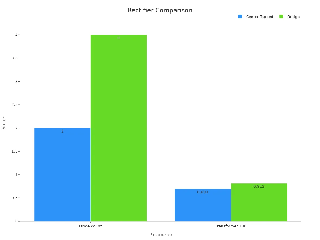
| Number of Diodes | 2 | 4 |
| Peak Inverse Voltage (PIV) | 2Vm | Vm |
| Transformer Utilization Factor (TUF) | 0.693 | 0.812 |
| Maximum Efficiency | 81.2% | 81.2% |
| Ripple Factor | 0.48 | 0.48 |
| Form Factor | 1.11 | 1.11 |
| Output Frequency | 2f | 2f |
The bridge rectifier requires twice as many diodes as the center-tapped full wave rectifier. This design reduces the stress on each diode because the peak inverse voltage is lower in the bridge circuit.
What Are the Transformer Requirements?
The transformer setup marks another key difference. The full wave rectifier needs a center-tapped transformer, which splits the AC voltage into two equal halves. This requirement can make the transformer larger and more expensive. The bridge rectifier does not need a center tap. It works with a simple transformer or even directly with the AC supply. This feature makes the bridge rectifier easier and cheaper to use in many beginner projects.
Tip: Bridge rectifiers save space and cost by removing the need for a center-tapped transformer.
How Do Voltage Drop and PIV Differ?
Voltage drop and peak inverse voltage (PIV) are important when comparing these rectifiers. In a bridge rectifier, current passes through two diodes during each half-cycle, causing a total voltage drop of about 1.4 V (0.7 V per diode). The full wave rectifier with a center tap has current passing through only one diode at a time, so the voltage drop is about 0.7 V. Lower voltage drop means more of the input voltage reaches the load.
The PIV rating tells how much reverse voltage each diode must withstand. In the bridge rectifier, each diode faces a PIV of Vm (the peak voltage). In the full wave rectifier, each diode must handle 2Vm, which means the diodes need to be rated for higher voltages.
| Parameter | Bridge Rectifier | Full-Wave Center-Tapped Rectifier |
|---|---|---|
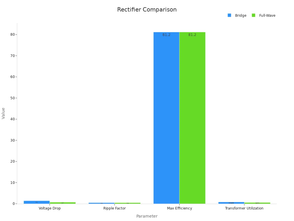
| Voltage Drop | Approximately 1.4 V | Approximately 0.7 V |
| Ripple Factor | 0.48 | 0.48 |
| Maximum Efficiency | 81.2% | 81.2% |
| Transformer Utilization Factor | 0.8106 | 0.573 |
| Output Frequency | Twice the AC supply frequency (2f) | Twice the AC supply frequency (2f) |
| DC Output Voltage | 2Vm/π | 2Vm/π |
Which Rectifier Offers Better Output and Ripple?
Both bridge and full wave rectifiers provide a smoother dc output than half-wave rectifiers. They double the output frequency, which makes it easier to filter out ripples using a capacitor. The ripple factor for both types is 0.48, showing that they produce similar levels of ripple in the dc output. However, the bridge rectifier has a higher transformer utilization factor, meaning it uses the transformer more efficiently.
Experimental data shows that the full wave rectifier reduces ripple voltage by more than half compared to a half-wave rectifier. It also increases the dc output voltage and load current by about 20%. Both rectifiers reach the same maximum efficiency of 81.2%. The dc output voltage for both is about 0.637 times the peak input voltage, after accounting for the voltage drop across the diodes.
Note: Using a larger smoothing capacitor can further reduce ripple in the dc output for both types of rectifiers.
Side-by-Side Comparison Table
| Feature | Bridge Rectifier | Full Wave Rectifier (Center-Tapped) |
|---|---|---|
| Number of Diodes | 4 | 2 |
| Transformer Requirement | No center tap needed | Center tap required |
| Voltage Drop | 1.4 V (two diodes) | 0.7 V (one diode) |
| Peak Inverse Voltage (PIV) | Vm | 2Vm |
| DC Output Voltage | 2Vm/π | 2Vm/π |
| Ripple Factor | 0.48 | 0.48 |
| Efficiency | 81.2% | 81.2% |
| Transformer Utilization | 0.81 | 0.69 |
| Cost | Lower | Higher (due to transformer) |
Summary of Main Technical and Practical Differences
The key difference between these rectifiers lies in the number of diodes and transformer needs. The bridge rectifier uses four diodes and does not need a center-tapped transformer, making it simpler and more cost-effective for beginners.
The full wave rectifier with a center tap uses only two diodes but requires a special transformer, which can increase cost and complexity.
The bridge rectifier has a higher voltage drop because current flows through two diodes, while the full wave rectifier has a lower voltage drop.
Both types deliver similar dc output voltage, ripple, and efficiency, but the bridge rectifier uses the transformer more efficiently.
For most beginner projects, the bridge rectifier offers a smoother dc output, easier assembly, and lower cost.
What Are the Pros and Cons for Beginners?
What Are the Pros and Cons of Bridge Rectifiers?
Bridge rectifiers offer several advantages for beginners. They do not require a center-tapped transformer, which makes the design simpler and reduces cost. Many starter kits include this type of rectifier because it uses four diodes in a compact arrangement. The transformer utilization factor (TUF) for a bridge rectifier is 0.812, which means it uses the transformer more efficiently than other types. This efficiency helps deliver more power to the load.
Tip: Bridge rectifiers work well in small projects where space and cost matter.
However, bridge rectifiers have some drawbacks. The current passes through two diodes during each half-cycle, causing a higher voltage drop (about 1.4 volts total). This drop can lead to more heat and power loss. In high-power circuits, users may need to add a heat sink to manage the extra heat. The circuit also becomes slightly more complex because it uses four diodes instead of two.
Summary Table: Bridge Rectifier
| Advantage | Disadvantage |
|---|---|
| No center-tapped transformer | Higher voltage drop (1.4 V) |
| High transformer utilization (0.812) | More heat generation |
| Compact and widely available | Slightly more complex circuit |
| Uses both halves of AC waveform | Four diodes required |
What Are the Pros and Cons of Full-Wave Rectifiers?
A full-wave rectifier with a center-tapped transformer uses only two diodes. This design results in a lower voltage drop across the diodes, which means less power loss and less heat. The circuit is simpler because it has fewer components. Many learners find this simplicity helpful when first studying rectifiers.
On the other hand, the full-wave rectifier needs a center-tapped transformer. These transformers can be larger and more expensive. The transformer utilization factor is lower (0.692), so the transformer does not work as efficiently as in a bridge rectifier. This lower efficiency can affect the amount of power delivered to the load.
Note: Beginners may find the transformer requirement challenging when building their first circuits.
Summary Table: Full-Wave Rectifier
| Advantage | Disadvantage |
|---|---|
| Lower voltage drop (0.7 V) | Needs center-tapped transformer |
| Fewer diodes (2) | Lower transformer utilization (0.692) |
| Simpler circuit | Transformer can be bulky and costly |
Both types of rectifier have strengths and weaknesses. Beginners should consider the project requirements, available parts, and desired efficiency before choosing.
Which Rectifier Is Better for Beginners?
What Is the Best Practical Recommendation?
Many beginners want a rectifier that is easy to build, reliable, and cost-effective. Bridge rectifiers meet these needs for most starter projects. They do not require a center-tapped transformer, which makes the circuit simpler and less expensive. Most electronics kits include four standard diodes, so beginners can assemble a bridge rectifier with parts they already have. The bridge design also provides good efficiency and a steady DC output, which helps protect sensitive components.
A full-wave rectifier with a center-tapped transformer works well in some cases. It uses only two diodes, which means less voltage drop and less heat. However, the need for a special transformer can make the project more complex and costly. Many beginners find it easier to use a bridge rectifier because it works with a standard transformer or even directly from the AC supply.
Tip: Beginners often choose bridge rectifiers for their first power supply circuits because they are simple and do not need special transformers.
What Are the Best Uses for Each Rectifier?
Different rectifier types fit different beginner projects. The table below shows how each type matches common needs:
| Rectifier Type | Diode Count | Efficiency | Ripple Voltage | Best Use Cases in Beginner Projects |
|---|---|---|---|---|
| Half-wave | 1 | Low | High | Simple, low-cost projects; signal detection, battery charging, dimming lamps |
| Full-wave (center-tap or bridge) | 2 or 4 | High | Low | Higher power and better DC quality needed; power supplies, radio receivers, flame detectors |
Beginners often use half-wave rectifiers for basic tasks like signal detection or charging small batteries. These circuits do not need high efficiency or smooth DC output. For projects that need stable and higher quality DC, such as power supplies or radio receivers, a full-wave rectifier or bridge rectifier works best. These designs provide better efficiency and lower ripple voltage, which helps devices run smoothly.
Note: Choosing the right rectifier depends on the project’s power needs and the quality of DC output required.
Bridge rectifiers and full wave rectifiers both convert AC to DC, but they differ in design and ease of use. Bridge rectifiers use four diodes and do not need a center-tapped transformer, making them simpler for beginners. Silicon diodes, often used in these circuits, offer low leakage current, high breakdown voltage, and stable performance.
Maximum rectifier current can reach thousands of amps
Typical forward voltage drop is about 0.7V
Reverse leakage current stays in the nanoampere range
For most beginner projects, bridge rectifiers with silicon diodes provide reliable and easy-to-build solutions. Beginners should match their choice to project needs and keep exploring electronics basics.
Frequently Asked Questions
Can you use a bridge rectifier for any AC voltage?
Yes, you can use a bridge rectifier for almost any AC voltage, provided the diodes are rated for the specific peak inverse voltage (PIV) and forward current. Always ensure your components exceed the circuit's maximum expected voltage and current to prevent catastrophic failure and overheating.
Why do you need a transformer in rectifier circuits?
A transformer is essential in rectifier circuits to step down high-voltage mains AC to a safer, lower voltage suitable for electronic components. Additionally, it provides galvanic isolation between the dangerous AC power grid and the low-voltage DC output, significantly improving overall circuit safety and stability.
Which rectifier gives a smoother DC output?
Both bridge and full-wave rectifiers provide a smoother DC output than half-wave rectifiers because they utilize both halves of the AC cycle. However, to achieve a truly flat DC signal, you must add a smoothing capacitor to filter out the remaining ripple voltage from the rectified waveform.
How do you know which rectifier to choose for your project?
Choose a bridge rectifier for simplicity, lower cost, and space-saving designs, as it eliminates the need for a bulky center-tapped transformer. Opt for a center-tapped full-wave rectifier if your project demands a lower voltage drop and you already have the specific transformer available in your workspace.
 UTMEL
UTMEL
We are the professional distributor of electronic components, providing a large variety of products to save you a lot of time, effort, and cost with our efficient self-customized service. careful order preparation fast delivery service
 Modeling Wide Band-Gap Semiconductors for Enhanced PerformanceRakesh Kumar, Ph.D.31 January 20243575
The article delves into the challenges faced by silicon-based power electronic devices and highlights the potential of wide band-gap semiconductors. It also emphasizes the importance of modeling power semiconductor devices and provides insights into various models. For electrical energy conversion to be dependable and effective, power electronics and semiconductor device technologies are essential.
Read More Optimizing Energy Management with Non-Isolated DC-DC ConvertersRakesh Kumar, Ph.D.04 February 20243231
The article classifies DC-DC converters and discusses the benefits and limitations of them. It proposes a modified DC-DC converter topology that combines the Cuk and Positive Output Super Lift Luo topologies to achieve a higher voltage gain with fewer components.
Read More ‘6G Networks’ - Pioneering the Next Era of Connectivity And InnovationRakesh Kumar, Ph.D.18 March 20243578
The article provides a comprehensive overview of the evolving landscape of mobile networks, the requirements that will shape the future of mobile communication, and the innovative technologies driving the transition to 6G.
Read More Review of IoT-Based Smart Home Security Systems- Part 1Rakesh Kumar, Ph.D.28 March 20243983
The article discusses the evolution of IoT-based smart home security systems, integrating advanced technologies like Raspberry Pi, PIR sensors, and voice recognition for enhanced user experience and efficiency.
Read More Understanding Photodiodes: Working Principles and Applications - Part 2Rakesh Kumar, Ph.D.24 May 20245094
The article provides a comprehensive overview of photodiodes, focusing on their operational principles, key factors affecting their efficiency, advantages, and disadvantages, and highlights their diverse applications.
Read More
Subscribe to Utmel !
![535S]() 535S
535SSwitchcraft
![595001]() 595001
595001Multicomp
![24-6337-8806]() 24-6337-8806
24-6337-8806NTE ELECT
![1830-10F]() 1830-10F
1830-10FNTE ELECT
![75310]() 75310
75310interlight
![882218-000]() 882218-000
882218-000TE Connectivity
![7010S-10]() 7010S-10
7010S-10Mitutoyo
![EM4500-000]() EM4500-000
EM4500-000TE Connectivity
![014830-000]() 014830-000
014830-000TE Connectivity
![T0054475199]() T0054475199
T0054475199Apex Tool Group
