Product
 Brand
Brand Articles
 Tools
Tools
Basic Introduction to Hall Effect Sensors

What is Hall Effect and How Hall Effect Sensors Work?
Catalog
Ⅰ Introduction
The Hall effect sensor is a magnetic field sensor based on the Hall effect principle. The Hall effect is a magnetoelectric phenomenon discovered by American physicist Edwin Hall (1855-1938) in 1879 while studying the conductive mechanisms of metals at Johns Hopkins University. Initially observed in metallic conductors, researchers later found that semiconductors and conductive fluids also exhibit this effect, with semiconductors demonstrating significantly stronger Hall effects than metals.
Hall effect sensors have become indispensable components in modern technology, finding applications in industrial automation, detection systems, information processing, consumer electronics, automotive systems, and renewable energy. As of 2025, the global Hall effect sensor market has grown substantially, driven by the proliferation of electric vehicles (EVs), Internet of Things (IoT) devices, and advanced robotics systems.
Hall effect measurements remain fundamental for characterizing semiconductor materials, enabling determination of critical parameters including conductivity type (n-type or p-type), carrier concentration, and carrier mobility. These measurements are essential in modern semiconductor manufacturing and materials research.
Ⅱ How Does a Hall Sensor Work?
The operating principle of Hall effect sensors is based on the Hall voltage (UH) generated when a current-carrying conductor is placed in a magnetic field. The magnitude of the Hall potential depends on several key factors:
RH - Hall coefficient (material-dependent constant)
I - Bias current through the Hall element
B - Magnetic field strength (magnetic flux density)
d - Thickness of the semiconductor material
The relationship is expressed as: UH = (RH × I × B) / d
For a given Hall device with fixed bias current I, the Hall voltage UH is directly proportional to the measured magnetic field strength B, making it an excellent magnetic field detector.
A typical Hall element features four terminals: two serve as input terminals for the bias current I, while the other two function as output terminals for the Hall voltage. When the output terminals form an external circuit, a Hall current flows. Modern Hall sensors typically use precision voltage references or constant current sources for biasing to ensure measurement accuracy and stability.
High-sensitivity Hall elements often incorporate high-permeability magnetic alloy concentrators to amplify the magnetic field at the sensing element. While these designs increase sensitivity, they typically saturate at relatively low magnetic flux densities (around 0.05T or 500 Gauss). Modern Hall sensors use advanced materials and designs to extend their operating range and improve linearity.
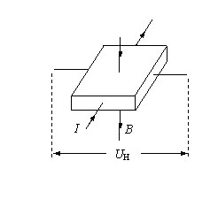
Figure 1. Hall Effect Principle
When a control current I flows through a semiconductor plate and a perpendicular magnetic field with flux density B is applied, a Hall voltage UH develops in the direction perpendicular to both the current and magnetic field. This voltage results from the Lorentz force acting on charge carriers (electrons and holes) moving through the magnetic field.
The Lorentz force causes charge carriers to accumulate on one side of the conductor, creating a potential difference across the width of the material. This Hall voltage is typically in the millivolt range but can be amplified using integrated circuits to produce usable signal levels.
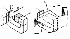
Figure 2. Hall Effect Sensor Operating Principle
1 - Hall semiconductor element; 2 - Permanent magnet; 3 - Rotating vane (magnetic flux modulator)
In practical applications, Hall sensors often use a rotating vane or ferromagnetic target to modulate the magnetic field. When the vane passes between the magnet and Hall element, it redirects the magnetic flux away from the sensor, causing the Hall voltage to decrease or disappear. This on-off switching action enables applications such as position sensing, speed detection, and ignition timing in automotive systems. The contactless nature of Hall sensors allows them to detect rotation at any speed, including zero RPM, making them superior to inductive sensors for low-speed applications.
Ⅲ Hall Effect
The Hall effect occurs when a magnetic field perpendicular to the current flow in a conductor causes charge carriers to deflect to one side of the material. In semiconductors, both electrons (negative carriers) and holes (positive carriers) experience the Lorentz force, but in opposite directions due to their opposite charges.
This charge separation creates an electric field perpendicular to both the current direction and the magnetic field. The electric field grows until its force on the charge carriers exactly balances the magnetic Lorentz force, reaching an equilibrium state. At equilibrium, the built-in electric field (Hall field) prevents further charge accumulation, and subsequent carriers pass through without deflection. The voltage associated with this electric field is the Hall voltage.
The Hall effect is particularly significant in applied technology and materials science. When current (I) flows through a conductor (d) in a magnetic field (B) perpendicular to the current direction, a voltage (UH) develops in the direction perpendicular to both the current and magnetic field. This voltage is the Hall voltage, and the phenomenon is the Hall effect.
An analogy helps visualize this: imagine people walking uniformly across a road. When a perpendicular force (magnetic field) is applied, everyone gets pushed to one side of the road, creating a density difference between the two sides. This density difference is analogous to the voltage difference (Hall voltage) that develops across the conductor.
Hall devices utilize magnetic fields as the working medium to convert mechanical motion parameters into digital or analog voltage outputs, providing both sensing and switching functions. The choice of semiconductor material significantly affects the Hall coefficient and sensor performance. Common materials include:
Indium Arsenide (InAs) - Most commonly used, excellent Hall coefficient and temperature stability
Indium Antimonide (InSb) - Highest sensitivity but temperature-sensitive
Gallium Arsenide (GaAs) - Good high-temperature performance
Silicon (Si) - Lower sensitivity but excellent for integration with CMOS electronics
Modern automotive applications extensively use Hall devices, including: distributor signal sensors, ABS wheel speed sensors, vehicle speedometers and odometers, fluid level detectors, current sensors for electrical load monitoring and diagnostics, crankshaft and camshaft position sensors, electronic throttle position sensors, electric power steering torque sensors, and battery current monitoring in electric and hybrid vehicles.
Ⅳ Classification of Hall Effect Sensors
Hall effect sensors are primarily classified into two main categories: linear (analog) Hall effect sensors and digital (switch) Hall effect sensors. Each type serves different applications based on output requirements.
1. Digital (Switch) Type Hall Sensors
Digital Hall sensors consist of a Hall element, voltage regulator, differential amplifier, Schmitt trigger, and output stage, producing a binary (on/off) digital output. These sensors are ideal for position detection, speed sensing, and proximity switching applications.
As shown in Figure 3, BOP (operate point) represents the magnetic flux density at which the sensor switches to the "on" state (low output), while BRP (release point) indicates the flux density at which it returns to the "off" state (high output). The difference between BOP and BRP creates hysteresis, which prevents oscillation and provides stable switching behavior in noisy environments.
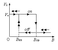
Figure 3. Digital Switch Type Hall Sensor Transfer Characteristic
Modern digital Hall sensors feature programmable switching thresholds, temperature compensation, and built-in diagnostics for automotive and industrial applications.
2. Latch Type Hall Sensors
Latch-type Hall sensors, also called bistable Hall switches, maintain their output state after the magnetic field is removed. As shown in Figure 4, when the magnetic flux density exceeds the operate point BOP, the output switches from high to low and remains latched in this state even after the magnetic field is removed. The output only changes when an opposite polarity magnetic field with flux density reaching BRP is applied.
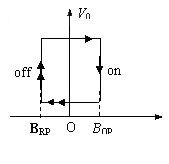
Figure 4. Latch Type Hall Sensor Transfer Characteristic
Latch-type sensors are commonly used in brushless DC motor commutation, rotary encoders, and applications requiring memory of magnetic pole passage.
3. Linear (Analog) Type Hall Sensors
Linear Hall sensors produce an output voltage proportional to the applied magnetic field strength. The sensor consists of a Hall element, linear amplifier, and output buffer stage, providing a continuous analog output signal.
As illustrated in Figure 5, the output voltage exhibits excellent linearity within the magnetic flux density range of B1 to B2. Outside this range, the sensor output saturates. Modern linear Hall sensors typically offer:
Ratiometric output (proportional to supply voltage)
Temperature compensation for stable operation from -40°C to +150°C
Low offset voltage and drift
High sensitivity (typically 5-50 mV/Gauss)
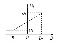
Figure 5. Linear Type Hall Sensor Transfer Characteristic
4. Open-Loop Current Sensors
Hall effect current sensors exploit the magnetic field generated by current flow through a conductor. According to Ampère's law, the magnetic field strength is proportional to the current, enabling contactless current measurement.
Open-loop Hall current sensors offer several advantages:
Galvanic isolation - Complete electrical isolation between measured circuit and sensor electronics
No power consumption from measured circuit - The sensor doesn't load the circuit under test
Wide bandwidth - Can measure DC, AC, and pulsed currents
High current capability - Suitable for measuring currents from milliamps to kiloamps
Compact design - Smaller than traditional current transformers
The basic design uses a magnetic core with an air gap containing the Hall element. The conductor carrying the measured current passes through the core, generating a magnetic field that the Hall sensor detects. Modern designs often use split-core configurations for easy installation without breaking the circuit.
5. Closed-Loop (Zero-Flux) Current Sensors
Closed-loop Hall current sensors, also called compensated or zero-flux sensors, offer superior accuracy and linearity compared to open-loop designs. These sensors actively null the magnetic field in the core using a compensation winding.
Operating Principle:
The primary current IP creates a magnetic field in the core
The Hall element detects this magnetic field and generates a voltage
This voltage is amplified and drives a compensation current IS through a secondary winding
The secondary winding creates a magnetic field opposing the primary field
The system reaches equilibrium when: IP × N1 = IS × N2
Therefore: IP = IS × (N2/N1)
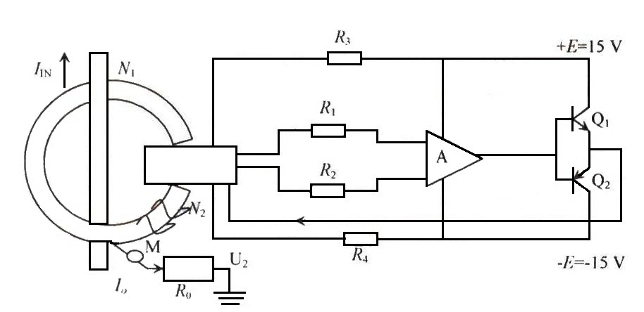
Figure 6. Closed-Loop Hall Current Sensor Architecture
The Hall element operates as a zero-flux detector, maintaining the core at near-zero magnetic flux. This configuration provides:
Excellent linearity (<0.1% typical)
High accuracy (±0.5% to ±1% of reading)
Fast response time (<1 μs)
Wide bandwidth (DC to >100 kHz)
Low temperature drift
Immunity to external magnetic fields
The response time from magnetic imbalance to re-equilibrium is typically less than 1 μs, making these sensors suitable for high-speed power electronics applications including motor drives, renewable energy inverters, and electric vehicle power systems.
Ⅴ Advantages of Hall Effect Sensors
Hall effect sensors offer numerous advantages that make them indispensable in modern electronic systems:
1. Universal Waveform Measurement
Hall sensors can accurately measure any current or voltage waveform including DC, AC, pulsed, and complex transient signals. The secondary current faithfully reproduces the primary waveform with minimal distortion. This capability far exceeds traditional current transformers, which are typically limited to 50/60 Hz sinusoidal waveforms and cannot measure DC.
2. Excellent Galvanic Isolation
Complete electrical isolation exists between primary and secondary circuits, with isolation voltages reaching 10 kV or higher in modern designs. This isolation provides safety, prevents ground loops, and enables measurement in high-voltage systems without risk to measurement electronics or personnel.
3. High Accuracy
Modern Hall current sensors achieve accuracy better than ±0.5% over their operating temperature range (-40°C to +85°C or higher). Closed-loop designs offer even better performance, with some precision models achieving ±0.2% accuracy. This makes them suitable for revenue metering, precision motor control, and power quality analysis.
4. Excellent Linearity
Closed-loop Hall sensors exhibit linearity better than 0.1% over their full measurement range, ensuring accurate measurement across the entire operating range without calibration at multiple points.
5. Wide Bandwidth
High-bandwidth Hall current sensors feature rise times under 1 μs and frequency response from DC to over 200 kHz. This enables measurement of fast transients in power electronics, such as IGBT switching currents in motor drives and inverters. Voltage sensors typically have lower bandwidth (DC to 20 kHz), with high-voltage models (6400 Vrms) having rise times around 500 μs and bandwidth near 700 Hz.
6. Wide Measurement Range
Hall sensors are available in a broad range of ratings: current measurement from milliamps to over 50 kA, and voltage measurement up to 7200 V or higher. This scalability makes them suitable for applications from small electronics to high-power industrial systems.
7. Contactless Operation
No physical contact with the measured circuit means no insertion loss, no heating, and no wear. This enables long service life and high reliability.
8. Compact Size and Low Weight
Modern Hall sensors are significantly smaller and lighter than equivalent current transformers or shunts, especially for high-current applications. This is particularly valuable in automotive, aerospace, and portable equipment.
9. No Insertion Impedance
Unlike shunt resistors, Hall sensors introduce no impedance in the measured circuit, eliminating power loss and voltage drop concerns.
Ⅵ Applications of Hall Effect Sensors
1. Automotive Industry Applications
Hall effect sensors have become ubiquitous in modern vehicles, with applications spanning powertrain, chassis, body control, and safety systems. The automotive industry represents one of the largest markets for Hall sensors, with each vehicle containing 10-30 or more Hall devices.
Key Automotive Applications:
Engine Management: Crankshaft and camshaft position sensing for ignition timing and fuel injection control. Modern engines use Hall sensors for variable valve timing (VVT) systems.
Transmission Systems: Gear position detection, transmission speed sensing, and shift control in automatic transmissions.
Chassis Systems: Wheel speed sensors for ABS (Anti-lock Braking System), ESC (Electronic Stability Control), and traction control. Modern vehicles use Hall sensors for each wheel.
Electric Power Steering (EPS): Torque sensing and motor position feedback for precise steering assistance.
Throttle Position Sensing: Contactless throttle position sensors in electronic throttle control systems (drive-by-wire).
Pedal Position Sensing: Accelerator and brake pedal position detection for drive-by-wire systems.
HVAC Systems: Blower motor speed control and air door position sensing.
Seat Position and Adjustment: Detecting seat position for memory functions and safety systems.
Electric Vehicle (EV) Applications:
The transition to electric vehicles has dramatically increased Hall sensor usage:
Battery Management Systems (BMS): High-precision Hall current sensors monitor charging and discharging currents, enabling accurate state-of-charge (SOC) estimation and cell balancing.
Motor Control: Brushless DC motor position sensing for traction motors and auxiliary motors. Modern EVs use Hall sensors for rotor position feedback in motor control algorithms.
DC-DC Converters: Current sensing for power conversion between high-voltage battery and low-voltage systems.
Onboard Chargers: AC and DC current monitoring for safe and efficient battery charging.
Inverter Current Sensing: Phase current measurement in traction inverters for field-oriented control (FOC) of AC motors.
Automotive Hall sensors must meet stringent requirements including AEC-Q100 qualification, operation over -40°C to +150°C (or higher for underhood applications), immunity to electromagnetic interference (EMI), and long-term reliability exceeding 15 years or 200,000+ miles.
2. Transportation and Metering Systems
Hall sensors play crucial roles in various transportation and metering applications beyond automotive:
Vehicle Metering Systems:
Modern taxi meters and ride-sharing vehicle systems use Hall sensors mounted on wheels for accurate distance measurement. A Hall switch (such as the A44E or modern equivalents like the AH3144E) detects rotation of a multi-pole magnet attached to the wheel. Each revolution generates pulses that a microcontroller counts and converts to distance traveled.
The system operates as follows: The Hall sensor output connects to an interrupt pin (e.g., INT0 on a microcontroller). Each wheel rotation (typically calibrated to 1 meter circumference) triggers an interrupt. When the pulse count reaches 1,000 (representing 1 kilometer), the microcontroller updates the fare calculation. Modern systems also incorporate GPS for enhanced accuracy and route verification.
Additional Transportation Applications:
Railway Systems: Wheel rotation sensing for speed measurement, odometry, and anti-slip control in locomotives and rail vehicles.
Bicycle Computers: Wheel speed and cadence (pedal rotation) sensing for cycling computers and e-bike systems.
Conveyor Systems: Speed monitoring and position detection in material handling and logistics systems.
Elevator Systems: Door position sensing, car position detection, and motor speed monitoring.
Escalator and Moving Walkway Systems: Speed monitoring and safety interlocks.
Utility Metering:
Smart Electricity Meters: Hall current sensors enable accurate energy measurement in smart grid applications.
Water Flow Meters: Hall sensors detect turbine rotation in water meters for residential and industrial applications.
Gas Flow Meters: Rotation sensing in positive displacement and turbine-type gas meters.
3. Power Electronics and Frequency Converters
Hall current sensors are essential components in modern power electronics, providing critical current feedback for control and protection:
Variable Frequency Drives (VFDs) and Inverters:
In frequency converters and motor drives, Hall current sensors serve multiple critical functions:
Overcurrent Protection: The primary role is protecting expensive power semiconductors (IGBTs, MOSFETs, SiC devices). With response times under 1 μs, Hall sensors can trigger protective shutdown before semiconductors reach destructive temperatures during overload or short-circuit conditions.
Current Feedback for Control: Precise current measurement enables advanced motor control algorithms including:
Vector control (Field-Oriented Control - FOC)
Direct Torque Control (DTC)
Sensorless motor control
Active damping of resonances
Power Quality Monitoring: Measuring input and output currents for power factor correction and harmonic analysis.
Energy Metering: Accurate energy consumption measurement for efficiency monitoring and billing.
Closed-Loop Operation in VFDs:
Modern VFDs predominantly use closed-loop (zero-flux) Hall current sensors for superior performance. The sensor maintains zero magnetic flux in the core through active compensation:
When the primary current IP flows through the power circuit, it generates a magnetic field in the sensor core. The Hall element detects this field and outputs a voltage proportional to the flux. This voltage is amplified and drives a compensation current IS through the secondary winding with N2 turns. The magnetic field from the secondary winding opposes the primary field. At equilibrium: IP × N1 = IS × N2, therefore IP = IS × (N2/N1)
Key Advantages in Power Electronics:
Galvanic Isolation: Complete electrical isolation between high-power circuits and sensitive control electronics, typically rated for 2-4 kV isolation.
No Insertion Loss: Unlike shunt resistors, Hall sensors don't introduce resistance or power loss in the measured circuit.
Wide Bandwidth: Ability to measure fast current transients during IGBT/MOSFET switching (typical dI/dt > 1000 A/μs).
DC Measurement Capability: Unlike current transformers, Hall sensors accurately measure DC and low-frequency AC currents.
Additional Power Electronics Applications:
Solar Inverters: DC and AC current sensing in photovoltaic inverters for maximum power point tracking (MPPT) and grid synchronization.
Wind Turbine Converters: Generator and grid-side current measurement in wind power systems.
UPS Systems: Battery current monitoring and AC output current control in uninterruptible power supplies.
Welding Equipment: High-current monitoring in arc welding and resistance welding systems.
Induction Heating: Current control in induction heating and melting applications.
Battery Chargers: Charging current control and monitoring in industrial battery charging systems.
DC Power Supplies: Output current regulation and protection in high-power DC supplies.
4. Modern Applications (IoT, Robotics, Consumer Electronics)
The proliferation of smart devices, IoT systems, and advanced robotics has created new applications for Hall effect sensors:
Consumer Electronics:
Smartphones and Tablets: Flip cover detection, stylus proximity sensing, and compass functionality (magnetometer).
Laptops: Lid open/close detection for power management and screen activation.
Gaming Controllers: Analog joystick position sensing with contactless Hall sensors for enhanced durability.
Smart Home Devices: Door/window sensors, appliance controls, and motorized curtain position feedback.
Drones: Brushless motor commutation and current sensing for flight control and battery management.
Industrial Robotics:
Joint Position Sensing: Absolute and incremental position feedback in robotic arms and collaborative robots (cobots).
Motor Current Monitoring: Torque estimation and collision detection through current sensing.
Gripper Force Control: Current-based force sensing in robotic grippers and end effectors.
Mobile Robots: Wheel speed sensing for odometry and navigation in autonomous mobile robots (AMRs) and automated guided vehicles (AGVs).
Medical Devices:
Ventilators: Flow sensing and valve position detection.
Infusion Pumps: Motor position and flow rate monitoring.
Surgical Robots: Precise position feedback in robotic surgical systems.
Prosthetics: Joint angle sensing in advanced prosthetic limbs.
Renewable Energy:
Solar Trackers: Position feedback for dual-axis solar tracking systems.
Wind Turbines: Pitch angle sensing, yaw position detection, and generator current monitoring.
Energy Storage Systems: Battery current monitoring in grid-scale and residential energy storage.
Aerospace and Defense:
Aircraft Systems: Flight control surface position sensing, landing gear position detection, and engine control.
Satellites: Solar panel deployment sensing and antenna positioning.
UAVs: Motor control and battery management in unmanned aerial vehicles.
Emerging Applications (2024-2025):
Electric Vertical Takeoff and Landing (eVTOL) Aircraft: Motor current sensing and position feedback in urban air mobility vehicles.
Wireless Power Transfer: Current monitoring in high-power wireless charging systems for EVs.
Quantum Computing: Magnetic field sensing in superconducting quantum computers.
Hydrogen Fuel Cells: Current monitoring in fuel cell stacks and power conditioning systems.
Conclusion
Hall effect sensors have evolved from simple magnetic field detectors to sophisticated, integrated sensing solutions that are indispensable in modern technology. Their unique combination of contactless operation, wide bandwidth, galvanic isolation, and ability to measure DC and AC signals makes them irreplaceable in applications ranging from automotive systems to renewable energy, from consumer electronics to industrial automation.
As we progress through 2025 and beyond, Hall effect sensors continue to evolve with improvements in sensitivity, accuracy, temperature stability, and integration with digital signal processing. The growing adoption of electric vehicles, renewable energy systems, and IoT devices ensures that Hall sensors will remain critical components in the transition to a more electrified and connected world.
Recent advances include programmable Hall sensors with configurable switching thresholds, integrated diagnostics for functional safety (ISO 26262), and ultra-low-power designs for battery-operated IoT devices. The development of wide-bandgap semiconductors (SiC, GaN) in power electronics has also driven demand for faster, more accurate Hall current sensors capable of measuring the rapid current transients in next-generation power converters.
Recommended Articles:
Working Principle and Development of Magnetic Sensors
Hall Effect Sensors in Electric Vehicles: Applications and Future Trends
 UTMEL
UTMEL
We are the professional distributor of electronic components, providing a large variety of products to save you a lot of time, effort, and cost with our efficient self-customized service. careful order preparation fast delivery service
How does a Hall effect sensor work?
Using semiconductors (such as silicon), Hall effect sensors work by measuring the changing voltage when the device is placed in a magnetic field. In other words, once a Hall effect sensor detects that it is now in a magnetic field, it is able to sense the position of objects.
Are Hall effect sensors analog or digital?
A HALL effect sensor is a transducer that varies its output in response to a magnetic field. ... If the voltage variation is linear then the Hall sensors are linear (analog). If the voltage will jump form 0 V to 5 V and back then the Hall sensors are digital.
Is a Hall effect sensor active or passive?
Both are controlled and activated by means of an external magnetic field – however a Hall effect sensor still requires an electrical circuit to operate, which needs power even when the sensor is in a passive state as its construction principle is based on the provision of an output signal.
What triggers a Hall effect device?
Hall Effect Sensors are devices which are activated by an external magnetic field. ... When the magnetic flux density around the sensor exceeds a certain pre-set threshold, the sensor detects it and generates an output voltage called the Hall Voltage, VH.
How do Hall effect sensors fail?
The Hall sensor is designed to flow 20 milliamps or less. The resistor is located in the signal circuit so it can limit the current flowing through that circuit. If this resistor drops its resistance, the current flow would increase, creating multiple Hall sensor failures.
 The Key Role of Electronic Components in IoT DevicesUTMEL01 September 20235785
The article discusses the pivotal role of electronic components in Internet of Things (IoT) devices. IoT devices work by capturing real-world data using sensors, processing it through a microcontroller, and then sending it to the cloud for further analysis.
Read More Accelerometer Sensors Guide: Working Principle, Circuit Design, Specifications, and ApplicationsUTMEL25 June 2026134
A practical accelerometer sensor guide covering working principles, MEMS and piezoelectric types, datasheet specifications, circuit design, mounting, applications, and selection.
Read More How to Identify the Perfect Proximity Sensor for Your ApplicationUTMEL19 July 20251698
Find the best proximity sensors for your project by evaluating material, sensing range, environment, and system needs to ensure optimal performance and reliability.
Read More Trusted Vibration Sensors for Homeowners and Industry ProfessionalsUTMEL17 July 20251344
Compare top vibration sensors for home and industrial use. Find trusted options for security, predictive maintenance, and equipment protection.
Read More Wiring and Mounting Photoelectric Sensors in 2025UTMEL15 July 20251546
Wire and mount photoelectric sensors in 2025 with step-by-step safety, wiring, and alignment tips for reliable installation and optimal sensor performance.
Read More
Subscribe to Utmel !
![EBM8CH250H]() EBM8CH250H
EBM8CH250HMenda
![EK60CS005]() EK60CS005
EK60CS005Menda
![73865]() 73865
73865OSRAM
![35065]() 35065
35065Menda
![EPM80BS602]() EPM80BS602
EPM80BS602Menda
![EP80WV031]() EP80WV031
EP80WV031Menda
![37786]() 37786
37786Elesa USA Corporation
![EPM75CS150]() EPM75CS150
EPM75CS150Menda
![90G LARGE]() 90G LARGE
90G LARGEMenda
![EK80CS005]() EK80CS005
EK80CS005Menda