Product
 Brand
Brand Articles
 Tools
Tools
Types and Application of Position Sensors
Catalog
|
I Classification of Position Sensors

A position sensor is a device that detects the position of a measured object and converts it into a usable output signal. Position sensors are critical components in modern automation, robotics, automotive systems, and industrial applications. They enable precise control and monitoring of mechanical movements, ensuring optimal performance and safety. There are primarily two main categories of position sensors: contact type and proximity type, each with distinct operating principles and applications.
1. Contact Position Sensor
Contact position sensors operate through physical contact between the sensor's actuator and the target object. When two objects touch and apply pressure, the contact terminal of the sensor is mechanically moved, triggering an electrical signal. Common types of contact position sensors include limit switches (also known as travel switches) and two-dimensional matrix position sensors.
Limit switches feature a simple structure, reliable operation, and cost-effective design. When a moving object contacts the limit switch, its internal contacts actuate to complete the control circuit. In CNC (Computer Numerical Control) machining centers, limit switches are commonly installed at both ends of the X, Y, and Z axes to control the travel range and prevent over-travel conditions, ensuring machine safety and precision. Modern limit switches are available in various configurations including roller lever, plunger, and whisker types, each suited for specific applications.

Contact Position Sensor
Two-dimensional matrix position sensors are sophisticated devices typically installed inside robotic grippers or palms to detect contact position and force distribution between the robot and objects. These sensors use arrays of pressure-sensitive elements to provide detailed spatial information about contact points, enabling delicate manipulation tasks and adaptive grasping strategies in advanced robotic systems.
2. Proximity Position Sensor
Proximity sensors are non-contact devices that detect the presence or position of objects within a specified sensing distance without requiring physical contact. These sensors emit an actuating signal when an object approaches within the preset detection range. The absence of mechanical contact eliminates wear and extends sensor lifespan, making proximity sensors ideal for high-speed applications and harsh environments.
There are several types of proximity sensors, each utilizing different physical principles:
Inductive proximity sensors - detect metallic objects using electromagnetic fields
Capacitive proximity sensors - detect both metallic and non-metallic objects by sensing changes in capacitance
Photoelectric sensors - use light beams (visible, infrared, or laser) to detect objects
Ultrasonic sensors - employ sound waves for distance measurement
Magnetic sensors - including Hall effect and reed switch sensors
In CNC machine tools and automated manufacturing systems, proximity switches are extensively used for tool selection control, table travel monitoring, cylinder and piston position detection, and workpiece presence verification. Their fast response time (typically microseconds) and high reliability make them indispensable in modern industrial automation.
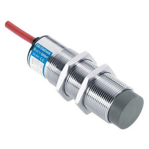
Wire Proximity Switches
II Application of Position Sensors
1. Brushless DC Motor
The position sensor is one of the three critical components of a brushless DC (BLDC) motor system, serving as the primary distinguishing feature from brushed DC motors. Its function is to detect the rotor's magnetic pole position during rotation and convert this positional information into electrical signals. These signals provide precise commutation timing information to the logic switching circuit, controlling the conduction and cutoff of power transistors in the proper sequence.
This precise control enables the current in the stator windings to reverse in synchronization with rotor position changes, creating a rotating magnetic field in the air gap that drives the permanent magnet rotor to rotate continuously. This electronic commutation replaces the mechanical commutator and brushes found in traditional DC motors, resulting in higher efficiency, longer lifespan, and reduced electromagnetic interference.
While sensorless BLDC motor control techniques have advanced significantly, using back-EMF (electromotive force) detection to determine rotor position, position sensors remain essential for many applications. Sensorless methods face limitations at startup and low speeds where the back-EMF signal is too weak to detect reliably. Position sensors provide accurate rotor position information across the entire speed range, from standstill to maximum RPM, ensuring smooth startup and low-speed operation.
Hall effect sensor ICs used as position sensors in BLDC motors are available in two main types: unipolar (switch type) and bipolar (latch type). Unipolar sensors activate when a magnetic field of sufficient strength and correct polarity is present, while bipolar sensors require alternating magnetic poles to switch states.
For electric vehicle motors and e-bike applications, both Hall sensor types can accurately measure rotor magnet position. BLDC motors using either sensor type exhibit equivalent performance characteristics, including output power, efficiency, and torque. Both sensor types are compatible with the same motor controller designs, providing flexibility in system design and component sourcing.
Position sensors provide multiple benefits for motor operation: they reduce acoustic noise by enabling smoother commutation, extend motor lifespan by eliminating brush wear, improve overall performance through precise timing control, and reduce energy consumption by optimizing switching efficiency. These advantages have driven widespread adoption of BLDC motors with position sensors in applications ranging from computer cooling fans to electric vehicles, industrial automation, and aerospace systems.
2. Crankshaft and Camshaft Position Sensors
Crankshaft and camshaft position sensors are fundamental components in modern engine management systems. Understanding their roles is essential:
Crankshaft Position Sensor (CKP), also known as the engine speed and crankshaft angle sensor, monitors crankshaft rotation angle and engine speed. This sensor sends critical timing information to the Engine Control Unit (ECU), which uses these signals to determine optimal ignition timing and fuel injection timing. The CKP sensor is essential for engine starting and running, as the ECU cannot operate the engine without accurate crankshaft position data.
Camshaft Position Sensor (CMP), also called the Cylinder Identification Sensor (CIS), collects valve camshaft position signals and transmits them to the ECU. To distinguish it from the crankshaft position sensor, it is commonly abbreviated as CMP or CIS.
The ECU uses the camshaft position signal to identify the compression top dead center (TDC) of cylinder 1, enabling sequential fuel injection control, precise ignition timing control, and knock detection. The camshaft position signal is particularly crucial during engine starting to identify the first ignition event. Since the camshaft sensor can determine which cylinder's piston is approaching TDC, it functions as a cylinder identification sensor, distinguishing between the compression and exhaust strokes.
Together, these sensors enable modern engines to achieve optimal fuel efficiency, reduced emissions, and improved performance through precise control of combustion timing and fuel delivery.
(1) Photoelectric Crankshaft and Camshaft Position Sensors
1) Structural Characteristics
Photoelectric crankshaft and camshaft position sensors consist of several key components: a signal disc (signal rotor), signal generator, distributor, sensor housing, and wiring harness connector. This optical sensing technology was more common in earlier engine designs but has largely been superseded by magnetic sensors in modern applications due to reliability and cost considerations.
The signal disc serves as the signal rotor and is press-fitted onto the sensor shaft, as illustrated in Figure 1. Near the disc's outer edge, two concentric circles of evenly-spaced transparent slots are precision-machined. The outer circle contains 360 transparent slots spaced at 1° intervals (each transparent slot and blocking section occupies 0.5°), generating crankshaft angle and speed signals with high resolution.
The inner circle features 6 transparent slots at 60° intervals to generate TDC signals for each cylinder. One slot is wider than the others, serving as a reference mark to generate the TDC signal specifically for cylinder 1, enabling the ECU to establish the engine's firing order and synchronize all control functions.

Figure 1. Working Principle of Photoelectric Position Sensors
The signal generator is mounted to the sensor housing and comprises an Ne signal (speed and angle) generator, a G signal (TDC) generator, and signal processing circuitry. Both the Ne and G signal generators consist of an LED (Light Emitting Diode) paired with a phototransistor or photodiode. The LEDs are positioned directly opposite their corresponding photodetectors, with the signal disc rotating between them.
2) Working Principle
The photoelectric sensor's operating principle is shown in Figure 1. The signal disc rotates between the LED and phototransistor (or photodiode).
When a transparent slot on the signal disc passes between the LED and phototransistor, light from the LED reaches the phototransistor. The phototransistor conducts, and its collector outputs a low voltage level (0.1-0.3V).
When an opaque section of the signal disc blocks the light path between the LED and phototransistor, the phototransistor switches off, and its collector outputs a high voltage level (4.8-5.2V).
As the signal disc rotates continuously, transparent slots and blocking sections alternately pass through the light path, causing the phototransistor's collector to output alternating high and low voltage levels. When the sensor shaft rotates with the crankshaft and camshaft, this alternating pattern generates pulse signals corresponding to shaft positions.
Since the crankshaft completes two revolutions during one engine cycle, the sensor shaft and signal disc complete one revolution. Therefore, the G signal sensor generates 6 pulse signals per engine cycle, while the Ne signal sensor produces 360 pulse signals. With the G signal slots spaced at 60° intervals, a pulse is generated every 120° of crankshaft rotation, earning it the designation "120° signal." This signal is typically designed to occur 70° before top dead center (BTDC 70°), allowing the ECU to control fuel injection and ignition advance angles optimally.
The wider transparent slot generates a signal corresponding to 70° BTDC for cylinder 1, providing the ECU with a reference point to establish the engine's firing order and synchronize all control functions. With the Ne signal slots at 1° intervals (0.5° transparent, 0.5° opaque), each pulse period represents 1° of crankshaft rotation. The 360 signals indicate a complete 720° crankshaft rotation (one engine cycle). For every 120° of crankshaft rotation, the G signal sensor produces one signal while the Ne signal sensor generates 60 signals.
(2) Magnetic Inductive Crankshaft and Camshaft Position Sensors
The magnetic inductive position sensor's working principle is illustrated in Figure 2. Magnetic flux lines follow this path:
permanent magnet N-pole → air gap between stator poles → rotor tooth → air gap between rotor tooth and stator magnetic pole → magnetic pole → flux concentrator → permanent magnet S-pole
When the signal rotor rotates, the air gap in the magnetic circuit changes periodically, causing periodic variations in magnetic reluctance and magnetic flux through the signal coil. According to the principle of electromagnetic induction, this changing magnetic flux induces an alternating electromotive force (EMF) in the sensing coil.

Figure 2. Working Principle of the Magnetic Inductive Position Sensor
When the signal rotor rotates clockwise and a rotor tooth approaches the magnetic pole, the air gap decreases, magnetic reluctance decreases, and magnetic flux φ increases. The rate of flux change increases (dφ/dt>0), and the induced EMF E is positive (E>0), as shown by curve abc in Figure 3. As the tooth edge aligns with the magnetic pole edge, flux φ increases most rapidly [dφ/dt=(dφ/dt)max], and EMF E reaches its maximum positive value (E=Emax), corresponding to point b in Figure 3. After passing point b, although flux φ continues increasing, its rate of change decreases, so induced EMF E decreases.
When the rotor tooth centerline aligns with the magnetic pole centerline (see Figure 2-b), the air gap is minimum, magnetic reluctance is minimum, and magnetic flux φ is maximum. However, since flux cannot increase further, the rate of flux change is zero, and induced EMF E is zero, corresponding to point c in Figure 3.

Figure 3. Magnetic flux φ Curve & the Electromotive Force E Curve
As the rotor continues rotating clockwise and the tooth moves away from the magnetic pole (see Figure 2-c), the air gap increases, magnetic reluctance increases, and magnetic flux φ decreases (dφ/dt<0). The induced EMF E becomes negative, as shown by curve cda in Figure 3. When the tooth edge leaves the magnetic pole edge, flux φ decreases most rapidly, the rate of flux change reaches its negative maximum [dφ/dt=-(dφ/dt)max], and induced EMF E reaches its negative maximum (E=-Emax), shown as point d in Figure 3.
Each time the signal rotor rotates past one tooth, a complete cycle of alternating EMF is generated in the sensing coil, with one maximum and one minimum value. The sensing coil outputs a corresponding alternating voltage signal.
A key advantage of magnetic inductive sensing is that no external power supply is required. The permanent magnet converts mechanical energy into electrical energy, and its magnetic energy remains constant. As engine speed changes, the rotor tooth speed changes, altering the rate of magnetic flux change in the core. Higher speeds produce greater flux change rates and higher induced EMF in the sensing coil. Figure 3 shows how magnetic flux and induced EMF vary with different rotation speeds.
The air gap between rotor teeth and the magnetic pole directly affects magnetic circuit reluctance and sensing coil output voltage, so it must be maintained within specifications. If the air gap changes, it must be adjusted according to manufacturer specifications. The air gap is typically designed to be 0.2-0.4mm for optimal performance and signal strength.
(3) Magnetic Inductive Crankshaft Position Sensor for Automobiles
1) Structural Characteristics
Magnetic inductive crankshaft position sensors for automobiles are typically mounted on the engine block near the clutch housing, consisting primarily of a signal generator and a signal rotor, as shown in Figure 4.

Figure 4. CKP Sensor Structure
The signal generator is secured to the engine block with mounting bolts and comprises a permanent magnet, sensing coil (also called signal coil), and wiring harness connector. The permanent magnet features a magnetic pole positioned directly opposite the signal rotor mounted on the crankshaft. The magnetic pole connects to a magnetic yoke to complete the magnetic circuit.
The signal rotor is a toothed disc with 58 teeth, 57 small gaps, and one large gap (missing teeth) evenly distributed around its circumference. The large gap generates a reference signal corresponding to a specific angle before the compression TDC of cylinder 1 or cylinder 4. The teeth and gaps on the signal rotor's circumference span the full 360° of rotation.
2) Working Condition
As the position sensor rotates with the crankshaft, each time the signal rotor passes one tooth, a periodic alternating EMF is generated in the sensing coil, outputting a corresponding alternating voltage signal.
The signal rotor's large gap (missing teeth) produces a distinctive signal pattern. When the missing teeth section passes the magnetic pole, the signal voltage duration is longer, generating a wide pulse signal corresponding to a specific angle before TDC of cylinder 1 or 4.
When the Engine Control Unit (ECU) receives the wide pulse signal, it recognizes that TDC of cylinder 1 or cylinder 4 is approaching. The camshaft position sensor signal determines whether cylinder 1 or cylinder 4 is on the compression stroke. With 58 teeth on the signal rotor, each complete rotor revolution (one crankshaft revolution) generates 58 alternating voltage signals input to the ECU.
Each time the ECU receives 58 signals from the crankshaft position sensor, it knows the crankshaft has completed one revolution. If the ECU receives 116,000 signals within 1 minute, it calculates crankshaft speed n as 2,000 rpm (n=116,000/58=2,000 rpm). Similarly, the ECU calculates engine crankshaft speed based on the number of signals received per minute.
The engine speed signal and load signal are the most critical control signals in electronic engine management systems. Based on these two signals, the ECU calculates three fundamental control parameters: base fuel injection timing, base ignition advance angle, and ignition dwell angle (coil charging time).
(4) Hall-Type Crankshaft and Camshaft Position Sensors
1) Structure and Working Principle
Hall-type crankshaft and camshaft position sensors, like other Hall effect sensors, operate based on the Hall effect principle, classifying them as Hall effect position sensors.

Figure 5. Principle of Hall Effect
Hall Effect
The Hall effect was discovered by Dr. Edwin Hall, a physicist at Johns Hopkins University in the United States, in 1879. He found that when a current-carrying rectangular conductor (originally platinum) is placed perpendicular to magnetic field lines with magnetic flux density B (see Figure 5), a voltage UH appears across the conductor's lateral surfaces, perpendicular to both the magnetic field direction and current flow direction.
When the magnetic field disappears, the voltage disappears immediately. This voltage, later termed Hall voltage, is proportional to both the current I and magnetic flux density B:
![]()
KH — Hall Coefficient
d — Thickness of conductor
Devices utilizing the Hall effect are called Hall elements, and sensors incorporating Hall elements are called Hall sensors. The Hall effect can detect voltage by switching magnetic fields on and off, and can also measure current flowing in wires since the magnetic field strength around a wire is proportional to the current.
Since the 1980s, Hall sensors in automotive applications have increased dramatically. This growth stems from two key advantages:
Output voltage signal resembles a square wave, providing clean digital signals
Signal amplitude is independent of the measured object's speed or rotation rate
Unlike magnetic inductive sensors, Hall sensors typically require an external power supply, usually 5V or 12V from the vehicle's electrical system.
2) Basic Structure of Hall Sensor
Hall sensors consist primarily of a trigger wheel (rotor), Hall integrated circuit (IC), magnetic yoke, and permanent magnet. The trigger wheel mounts on the rotating shaft with vanes or blades. In Hall-type ignition systems, the number of vanes equals the number of engine cylinders. As the trigger wheel rotates with the shaft, vanes pass through the air gap between the Hall IC and permanent magnet. Modern Hall ICs integrate the Hall element, amplification circuit, voltage regulation circuit, temperature compensation circuit, signal conversion circuit, and output circuit in a single package.
3) Working Principle of Hall Sensor
When the sensor shaft rotates, trigger wheel vanes pass through the air gap between the Hall IC and permanent magnet. When a vane exits the air gap, magnetic flux from the permanent magnet passes through the Hall IC and magnetic steel sheet, forming a complete magnetic circuit. The Hall element generates a voltage (UH = 1.9-2.0V), the output stage transistor of the Hall IC conducts, and the sensor outputs a low signal voltage. In actual measurements with power supply voltage Ucc = 14.4V or 5V, the signal voltage U0 = 0.1-0.3V.
When a vane enters the air gap, it shunts the magnetic field away from the Hall IC. The Hall voltage UH becomes zero, the IC output stage transistor cuts off, and the sensor outputs a high signal voltage. In actual measurements with Ucc=14.4V, signal voltage U0=9.8V; with Ucc=5V, signal voltage U0=4.8V.
4) Structure of Hall-Type Camshaft Position Sensor
Hall-type camshaft position sensors used in automobiles mount at one end of the engine's intake camshaft. The structure is shown in Figure 6, consisting primarily of a Hall signal generator and signal rotor. The signal rotor, also called trigger wheel, mounts on the intake camshaft using positioning bolts and a retaining plate.

Figure 6. Structure of Hall-Type Camshaft Position Sensor
The signal rotor's vane features a window opening. The window corresponds to a low-level signal output, while the vane (solid section) corresponds to a high-level signal output.
The Hall signal generator comprises a Hall integrated circuit, permanent magnet, and magnetic steel sheet. The Hall element uses silicon semiconductor materials, positioned with a 0.2-0.4mm gap from the permanent magnet. As the signal rotor rotates with the intake camshaft, vanes and windows alternately pass through the gap between the Hall IC and permanent magnet.
The sensor connector has three terminals: Terminal 1 is the positive power supply terminal connected to the ECU. Terminal 2 is the signal output terminal connected to the ECU. Terminal 3 is the negative power supply terminal (ground) connected to the ECU. The specific terminal numbers may vary by manufacturer and vehicle model.
5) Working Conditions
According to Hall sensor operating principles, when a vane (solid section) enters the air gap, the Hall element generates no voltage, and the sensor outputs a high-level signal (approximately 5V). When the vane exits the air gap (window passes through), the Hall element generates voltage, and the sensor outputs a low-level signal (approximately 0.1V).
Figure 7 shows the relationship between camshaft position sensor and crankshaft position sensor output signal voltages. For every two crankshaft revolutions (720°), the Hall sensor signal rotor completes one revolution (360°), generating one low-level signal and one high-level signal. The low-level signal corresponds to a specific angle before cylinder 1's compression TDC.

Figure 7. Relationship of Output Waveforms of Camshaft and Crankshaft Position Sensors
During engine operation, signal voltages from the magnetic inductive crankshaft position sensor (CKP) and Hall camshaft position sensor (CMP) continuously input to the ECU. When the ECU simultaneously receives the low-level signal corresponding to the crankshaft sensor's missing teeth and the low-level signal corresponding to the camshaft sensor's window, it recognizes that cylinder 1's piston is in the compression stroke while cylinder 4's piston is in the exhaust stroke.
The ECU controls ignition advance angle based on output signals corresponding to the crankshaft position sensor's individual teeth. After recognizing cylinder 1's compression TDC position, the ECU performs sequential fuel injection control and ignition timing control for each cylinder in the correct firing order.
If engine knock occurs, the ECU can determine which cylinder is knocking based on knock sensor input signals, then reduce that cylinder's ignition advance angle to eliminate knock and prevent engine damage.
(5) Differential Hall-Type Crankshaft Position Sensor
Differential Hall sensors, also called dual Hall sensors, feature a structure similar to magnetic inductive sensors, as shown in Figure 8-a. They consist of a toothed signal rotor and Hall signal generator.
The differential Hall sensor operates on the same principle as standard Hall sensors. According to Hall sensor operating principles, when missing teeth or teeth on the engine flywheel pass the two probes of the differential Hall circuit, the air gap between teeth (or missing teeth) and Hall probes changes, causing corresponding magnetic flux changes.
An alternating voltage signal is generated in the Hall elements, as shown in Figure 8-b. The output voltage is the superposition of two Hall signal voltages. Because the output signal is superimposed, the air gap between teeth and signal generator can be increased to 1.0±0.5mm (compared to 0.2-0.4mm for standard Hall sensors). This allows the signal rotor to be manufactured as a toothed disc structure similar to magnetic inductive sensor rotors, simplifying installation.
In automotive applications, the toothed rotor is typically mounted on the engine crankshaft or flywheel, providing robust and reliable position sensing for engine management systems.

Figure 8. Differential Hall-Type Crankshaft Position Sensor
III Frequently Asked Questions (FAQs)
Q1: What are the main advantages of Hall effect sensors over magnetic inductive sensors?
Hall effect sensors offer several key advantages: they produce square-wave digital signals that are easier to process, their output amplitude is independent of rotation speed (making them reliable at all speeds including zero), they provide consistent signal strength from startup through maximum RPM, and they typically have faster response times. However, they require external power supply, unlike magnetic inductive sensors which are self-generating.
Q2: Can a vehicle run without a camshaft position sensor?
Most modern vehicles can start and run without a functioning camshaft position sensor, but performance will be degraded. The ECU will use the crankshaft position sensor alone and operate in "limp mode," using sequential fuel injection timing based on crankshaft position only. This results in reduced fuel efficiency, increased emissions, potential rough idle, and possible starting difficulties. Some advanced engines with variable valve timing may not run properly without the CMP sensor.
Q3: What causes position sensor failure?
Common causes of position sensor failure include: excessive heat exposure from engine operation, vibration damage to internal components, contamination from oil or debris affecting the air gap, electrical connector corrosion, damaged wiring harnesses, physical damage from impact or improper installation, and normal wear over time. Magnetic sensors can also fail if the air gap becomes too large due to mounting bracket wear or if the signal rotor becomes damaged.
Q4: How do you test a crankshaft position sensor?
Testing methods vary by sensor type. For magnetic inductive sensors, use a digital multimeter to measure AC voltage output while cranking the engine (should produce 0.2-2.0V AC depending on cranking speed). For Hall sensors, check for proper supply voltage (typically 5V or 12V), then verify the signal output switches between high and low as the engine rotates. An oscilloscope provides the most comprehensive testing, showing signal waveform quality, amplitude, and timing. Always check the air gap specification and verify proper rotor condition before condemning a sensor.
Q5: What is the difference between unipolar and bipolar Hall sensors?
Unipolar (switch-type) Hall sensors activate when exposed to a magnetic field of sufficient strength and correct polarity (typically south pole), and deactivate when the field is removed or weakened. Bipolar (latch-type) Hall sensors require alternating magnetic poles to change states—a south pole activates the sensor, and it remains active until a north pole is presented. Bipolar sensors provide more stable operation in the presence of magnetic field variations and are less susceptible to false triggering from stray magnetic fields.
Q6: Why do modern engines use multiple position sensors?
Modern engines use both crankshaft and camshaft position sensors to achieve precise control. The crankshaft sensor provides high-resolution position and speed information (often 60 pulses per revolution), while the camshaft sensor identifies which cylinder is on the compression stroke. This combination enables sequential fuel injection (injecting fuel only when the intake valve is open), precise ignition timing for each cylinder, variable valve timing control, and knock detection with cylinder identification. This multi-sensor approach optimizes fuel efficiency, reduces emissions, and maximizes engine performance.
Q7: What are the latest developments in position sensor technology?
Recent advances include: giant magnetoresistance (GMR) sensors offering higher sensitivity and accuracy, integrated sensor modules combining multiple sensing functions, wireless position sensors for difficult-to-access locations, MEMS-based sensors providing miniaturization and cost reduction, and smart sensors with built-in signal processing and diagnostic capabilities. For automotive applications, there's growing adoption of redundant sensor systems for safety-critical applications and sensors capable of operating in extreme temperature ranges for hybrid and electric vehicle powertrains.
Recommended Articles:
Car Sensors: Classification and Application
Working Principle and Application of Infrared Sensors
All You Need to Know about Ultrasonic Sensors
Article Update Information
Last Updated: October 31, 2025
Original Publication Date: 2020
Updates Made:
Corrected terminology: "travel switches" updated to "limit switches" (industry standard term)
Enhanced technical descriptions of Hall effect sensors and magnetic inductive sensors
Added information about modern sensor technologies including GMR sensors and MEMS-based sensors
Expanded coverage of sensor testing methods and diagnostic procedures
Added comprehensive FAQ section addressing common questions about position sensors
Updated information about sensorless motor control techniques
Clarified the distinction between unipolar and bipolar Hall sensors
Enhanced explanation of differential Hall sensors and their advantages
Added context about modern engine management systems and sensor redundancy
Corrected minor spelling and grammatical errors throughout
Updated technical specifications to reflect current industry standards
Technical Accuracy: All technical information has been reviewed and updated to reflect current industry standards and best practices as of October 2025. Sensor specifications, operating principles, and application examples remain accurate for modern automotive and industrial systems.
 UTMEL
UTMEL
We are the professional distributor of electronic components, providing a large variety of products to save you a lot of time, effort, and cost with our efficient self-customized service. careful order preparation fast delivery service
1.Which is the position sensor?
A position sensor is any device used for measuring the distance traveled by a body starting from its reference position. It measures linear or angular position in reference to a fixed point or arbitrary reference. The sensor can also be used to detect the presence or absence of an object.
2.How do position sensors work?
Optical position sensors operate using one of two principles. In the first type, light is transmitted from an emitter and sent over to a receiver at the other end of the sensor. In the second type, the emitted light signal is reflected from the object being monitored returned towards the light source.
3.Which type of materials can be detected by eddy current position sensor?
Eddy current type displacement sensor can detect metal objects because it uses high frequency magnetic field for the detection of objects.
4.What is potentiometer position sensor?
A potentiometer sensor measures the distance or displacement of an object in a linear or rotary motion and converts it into an electrical signal.
5.What is a linear position sensor?
Linear position sensors are devices that connect to an object or piece of machinery and convert the linear displacement of the object into an electrical signal that is proportional to the object's displacement.
 The Key Role of Electronic Components in IoT DevicesUTMEL01 September 20235602
The article discusses the pivotal role of electronic components in Internet of Things (IoT) devices. IoT devices work by capturing real-world data using sensors, processing it through a microcontroller, and then sending it to the cloud for further analysis.
Read More How to Identify the Perfect Proximity Sensor for Your ApplicationUTMEL19 July 20251516
Find the best proximity sensors for your project by evaluating material, sensing range, environment, and system needs to ensure optimal performance and reliability.
Read More Trusted Vibration Sensors for Homeowners and Industry ProfessionalsUTMEL17 July 20251193
Compare top vibration sensors for home and industrial use. Find trusted options for security, predictive maintenance, and equipment protection.
Read More Wiring and Mounting Photoelectric Sensors in 2025UTMEL15 July 20251412
Wire and mount photoelectric sensors in 2025 with step-by-step safety, wiring, and alignment tips for reliable installation and optimal sensor performance.
Read More Essential Tips for Picking the Best Gas SensorUTMEL15 July 20252734
Find out how to select gas sensors by matching target gases, environment, and compliance needs for reliable and accurate gas detection in any setting.
Read More
Subscribe to Utmel !
![EBM80TZ010B]() EBM80TZ010B
EBM80TZ010BMenda
![50G LARGE]() 50G LARGE
50G LARGEMenda
![ZJ9-NDT06FN1]() ZJ9-NDT06FN1
ZJ9-NDT06FN1Omron Automation and Safety
![UMYA-18-32-1]() UMYA-18-32-1
UMYA-18-32-1Omron Automation and Safety
![ZJ9-FL120N1]() ZJ9-FL120N1
ZJ9-FL120N1Omron Automation and Safety
![ZJ9-BRS1FW]() ZJ9-BRS1FW
ZJ9-BRS1FWOmron Automation and Safety
![ES75CS010]() ES75CS010
ES75CS010Menda
![ET70WV020]() ET70WV020
ET70WV020Menda
![EK80DS045]() EK80DS045
EK80DS045Menda
![SW6WFCAS-100]() SW6WFCAS-100
SW6WFCAS-100Menda