Product
 Brand
Brand Articles
 Tools
Tools
What is an Oxygen Sensor?
How Oxygen Sensor Works?

Table of Contents
Working Principle
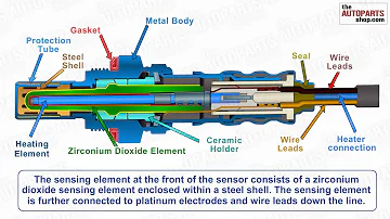
The oxygen sensor is a standard component in modern vehicles that uses ceramic sensitive elements to measure oxygen potential in the exhaust system. By applying the chemical equilibrium principle, it calculates oxygen concentration to monitor and control the air-fuel ratio, ensuring optimal product quality and emissions compliance.
Widely used in combustion atmosphere control for coal, oil, and gas furnaces, oxygen sensors represent the most effective combustion atmosphere measurement method available today. Their simple structure, rapid response speed, and ease of maintenance make them ideal for automotive applications.
The zirconia in automotive oxygen sensors functions as an electrolyte, similar to what's found in dry batteries. Under specific conditions, the difference in oxygen concentration between the inside and outside of the zirconia generates a potential difference—the greater the concentration difference, the greater the potential difference.
Technical Note
The atmosphere contains 21% oxygen. Exhaust gas from stoichiometric or rich mixture combustion contains virtually no oxygen, while exhaust from lean mixtures or resulting from bad ignition contains more oxygen (though still less than in the atmosphere).
Under high temperature and with platinum catalyzing, oxygen ions with negative charges are adsorbed on the inner and outer surfaces of the zirconia sleeve. The atmosphere side absorbs more negative ions than the exhaust side due to higher oxygen concentration, and this difference creates an electromotive force.
When oxygen concentration on the exhaust side is low (indicating a rich mixture), the sensor generates a high voltage (0.6-1V). This signal is sent to the Engine Control Unit (ECU) for amplification. The ECU interprets high voltage as indicating a rich mixture and low voltage as a lean mixture. Based on these readings, the computer adjusts fuel delivery to maintain the theoretical optimal air-fuel ratio of 14.7:1, making the oxygen sensor crucial for electronically controlled fuel metering.
Importantly, oxygen sensors only function effectively at high temperatures (above 300°C) and react most quickly to mixture changes at around 800°C. This characteristic changes significantly at lower temperatures.
Function
To achieve high exhaust purification rates and reduce carbon monoxide (CO), hydrocarbons (HC), and nitrogen oxides (NOx), modern vehicles employ three-way catalytic converters. However, to maximize the converter's effectiveness, the air-fuel ratio must be precisely controlled to approximate the theoretical air-fuel ratio. The catalytic converter is typically positioned between the exhaust manifold and the muffler.
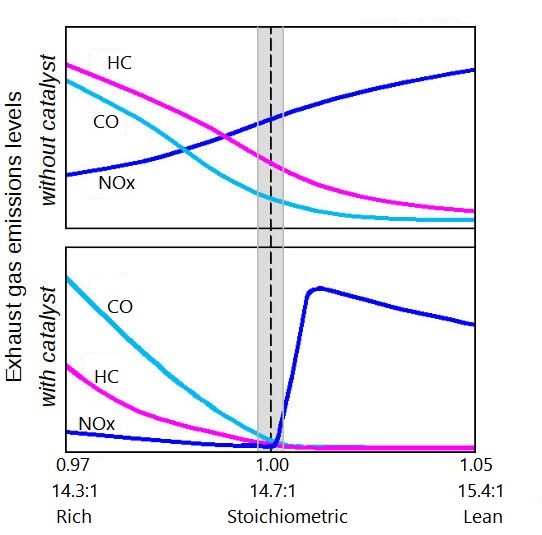
Gasoline engine catalyst efficiency as a function of air-fuel ratio
The oxygen sensor's voltage output changes dramatically near the theoretical air-fuel ratio (14.7:1). This characteristic allows it to detect oxygen concentration in exhaust gases and provide feedback to the ECU for air-fuel ratio control.
When the actual air-fuel ratio increases (leans out), oxygen concentration in the exhaust rises and the sensor transmits a lean state signal (low voltage: ~0V) to the ECU. Conversely, when the air-fuel ratio falls below the theoretical value (rich mixture), exhaust oxygen concentration decreases, and the sensor sends a rich signal (high voltage: ~1V) to the ECU.
The ECU determines whether to enrich or lean the mixture based on these voltage readings and adjusts injection duration accordingly. If the oxygen sensor malfunctions and outputs abnormal readings, the ECU cannot accurately regulate the air-fuel ratio. The oxygen sensor also compensates for air-fuel ratio errors caused by mechanical wear in the electronic fuel injection (EFI) system, making it the only truly "intelligent" sensor in the EFI system.

Working diagram of an electronic fuel injection (EFI) system
The sensor measures excess oxygen in engine exhaust post-combustion and converts this into a voltage signal for the engine computer, enabling closed-loop control with excess air factor targeting. This ensures the three-way catalytic converter achieves maximum conversion efficiency for HC, CO, and NOx pollutants, optimizing exhaust purification.
Classification
In practical applications, oxygen sensors come in two primary types: zirconia oxygen sensors and titanium oxygen sensors. They can further be categorized as single-lead, double-lead, or three-lead types. Typically, zirconia oxygen sensors are single-lead, titanium oxygen sensors are double-lead, and heated zirconia oxygen sensors feature three leads. These different types cannot be used interchangeably.
Zirconia Oxygen Sensor
Structure
The zirconia oxygen sensor primarily consists of a zirconia (ZrO2) element and a protective sheath. These sensors come in heated and unheated variants, with heated sensors featuring a heating rod in the center of the zirconia tube. The zirconia tube itself is made of ceramic material and secured in a sleeve with mounting threads.
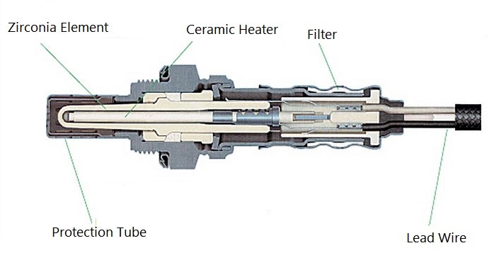
Structure of a typical zirconia oxygen sensor
Both inner and outer surfaces of the zirconia tube are coated with a porous platinum film that acts as an electrode. To protect the platinum film from exhaust gas corrosion, the outer platinum layer is covered with a porous ceramic coating. The assembly includes a protective sleeve with notches or holes and a metal terminal sheath with an air hole that connects the inner surface of the zirconia tube to atmospheric air. The platinum electrode on the inner surface connects to the outside through an insulating sleeve.
Features
Advantages: Simple structure, quick response, easy maintenance, convenient use, and accurate measurement. Using this sensor to monitor and control combustion atmosphere not only stabilizes and improves product quality but also shortens production cycles and saves energy.
Disadvantages: The sensor's optimal characteristics are only fully realized at high temperatures (approximately 600°C). At lower temperatures, performance changes significantly.
Titanium Oxygen Sensor
Working Principle
Unlike zirconia sensors that generate voltage signals, titanium oxygen sensors (TiO2) use resistance changes to determine oxygen content. Above certain temperatures, titanium's bond with oxygen weakens. In low-oxygen environments, oxygen is released, creating a low-resistance oxide semiconductor. Conversely, high oxygen environments form a high-resistance state. Similar to a water temperature sensor, this resistance change allows oxygen measurement when a reference voltage is applied.

Schematic representation of titanium dioxide (TiO2) sensor function
Features
The working principle of titanium sensors differs fundamentally from zirconia sensors. They utilize the conductivity changes in porous TiO2 conductors as oxygen content in exhaust gases fluctuates, earning them the alternative name "resistance oxygen sensors."
These sensors offer simple structure, compact size, and lower cost. However, when operating at 300-900°C, their resistance values change dramatically with temperature. To improve accuracy, manufacturers often employ another solid TiO2 conductor for temperature compensation.
Common Faults of Oxygen Sensors
Oxygen Sensor Poisoning
Sensor poisoning represents one of the most frequent and difficult-to-prevent failures. Vehicles that frequently use leaded gasoline are particularly susceptible—even new oxygen sensors may only function properly for a few thousand kilometers. Mild lead poisoning can sometimes be remedied by running a tank of unleaded fuel, which can remove surface lead and restore normal operation. However, if high exhaust temperatures have allowed lead to penetrate the sensor's interior, blocking oxygen ion diffusion, the sensor becomes permanently damaged and requires replacement.
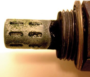
Visual of a poisoned oxygen sensor
Silicon poisoning also commonly affects oxygen sensors. Silicon dioxide generated from silicon compounds in gasoline and lubricating oil, as well as silicone gas released from improperly used silicone rubber gaskets, can render sensors ineffective. To prevent this, use high-quality fuel and lubricants, and select and install rubber gaskets properly. Avoid applying non-manufacturer-specified solvents or anti-sticking agents to the sensor.
Carbon Deposit
Poor engine combustion can lead to carbon deposits forming on the oxygen sensor's surface. Oil or dust deposits inside the sensor can block atmospheric air entry, causing inaccurate signal output and preventing the ECU from properly adjusting the air-fuel ratio. Signs of carbon deposits include increased fuel consumption and noticeably higher emissions. Removing these deposits often restores normal sensor function.
Ceramic Chipping
The ceramic components of oxygen sensors are hard but brittle and can crack or break when struck by hard objects or exposed to strong airflow. Special care should be taken during handling and installation, and damaged sensors should be promptly replaced.
Burned Resistance Wire
In heated oxygen sensors, ablation of the heater's resistance wire prevents the sensor from reaching normal operating temperature, rendering it ineffective.
Disconnected Internal Circuit
Internal circuit disconnections prevent proper signal transmission, causing the sensor to malfunction.
Signal Clutter
Signal clutter refers to inconsistent or erratic output from the oxygen sensor, often indicating underlying issues with either the sensor itself or related engine systems.
Analysis of Signal Clutter
Causes
Oxygen sensor signal clutter typically stems from:
Cylinder misfires or incomplete combustion
System design issues, such as varying intake pipe channel lengths
Expanded system design problems resulting from engine and component aging (e.g., imbalanced cylinder pressure caused by different intake pipe channel lengths)
Bad Ignition Influence
Waveform glitches and clutter during bad ignition result from single or multiple incomplete or failed combustion events. In these cases, only part of the oxygen in the cylinder participates in combustion, with excess oxygen passing through to the exhaust system past the oxygen sensor. When the sensor detects changes in exhaust oxygen content, it rapidly generates low-voltage signals or glitches. A series of these high-frequency glitches forms what technicians refer to as "clutter."
Types of Bad Ignition
Firing System Issues: Problems with spark plugs, high-voltage power lines, distributor components, ignition coils, or primary ignition systems affecting one or more cylinders. These faults can typically be identified using an ignition oscilloscope.
Rich Mixture Issues: Bad ignition caused by excessively rich mixture delivery to the cylinder, resulting in an air-fuel ratio of approximately 13:1.
Lean Mixture Issues: Bad ignition resulting from insufficient fuel in the cylinder mixture, with air-fuel ratios approaching 17:1.
Cylinder Pressure Problems: Mechanical issues such as burned valves, broken or worn piston rings, worn camshafts, or stuck valves that reduce cylinder pressure before ignition, producing insufficient heat for proper combustion and increasing exhaust oxygen content.
Vacuum Leaks: Leaks affecting one or more cylinders can be diagnosed by adding propane to suspected leak areas (intake components, manifold gaskets, vacuum tubes, etc.). When propane addition strengthens the signal, spikes typically disappear. Vacuum leaks causing air-fuel ratios above 17:1 lead to misfires.
Fuel Injector Imbalance: Common in multi-point injection engines, where injectors deliver too much or too little fuel due to clogs or sticking. Cylinders receiving lean mixtures (>17:1 air-fuel ratio) or rich mixtures (<13:1) will misfire.
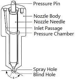
Fuel injection nozzle components and assembly
Troubleshooting Methods for Oxygen Sensors
Measure the Resistance
Use an ohmmeter to measure resistance between the oxygen sensor socket terminals (heater circuit). The heating resistor wires typically share the same color, making them easy to identify. Normal cold resistance is approximately 4 ohms. (Note: A typical four-wire oxygen sensor has its wires arranged in a row—one pair connects to the heating element; the other pair connects to the signal output.)
If you detect an open circuit or resistance outside normal parameters, replace the oxygen sensor. If resistance values appear normal, proceed to the next diagnostic step.
Measure the Power Supply Voltage
With the ignition switch on, measure voltage between the harness-side terminals of the oxygen sensor connector corresponding to the heating element. You should observe battery voltage. If voltage is low or absent, repair the circuit between the oxygen sensor connector and the injection relay.
Measure the Insulation to Ground
Use an ohmmeter to measure resistance between the heater element and the sensor housing, which should read as infinite (∞).
If there's continuity to ground, replace the oxygen sensor. If insulation is intact, proceed to the next diagnostic step.
Measure the Signal Voltage
Turn off the ignition switch and disconnect the 4-pin connector from the oxygen sensor.
Connect 12V battery power directly to the sensor's heating element using custom-made connectors with wires. Start the engine and measure voltage at the signal output terminal after two minutes.
Alternative Method
If creating custom connectors isn't feasible, you can start the engine, wait two minutes, then quickly disconnect the four-core connector and measure voltage at the sensor's signal terminals. Be aware that the sensor core will cool rapidly once disconnected from power, potentially increasing measurement error.
At idle after engine start, this output voltage should be very low according to normal operating principles. When increasing throttle, you should observe momentary voltage output corresponding to the rate of throttle change (voltage disappears once throttle position stabilizes). Faster throttle changes produce higher voltage readings, potentially reaching 0.9V maximum. When using an analog meter, inertia and damping factors typically limit readings to about 0.8V. (Note: Due to digital meters' response time limitations, they're less suitable for this measurement and may introduce significant error.)
If the oxygen sensor produces no voltage output, unchanging voltage values, minimal voltage fluctuations, or extremely slow voltage changes, the sensing element likely requires cleaning:
Remove the oxygen sensor.
Prepare a solution of 5-10% ferric trichloride with added hydrochloric acid. (The exact ratio depends on the sensor head's condition.)
Soak the sensor in this solution for 10-15 minutes, then rinse thoroughly with water. After cleaning, ensure all four holes around the sensor are unobstructed and the carrier visible from the bottom appears white. If cleaning results are unsatisfactory, repeat until the white carrier becomes visible.
After rinsing, reinstall the sensor and repeat the signal voltage measurement procedure. Generally, provided the internal ceramic body remains intact and the heating element functions properly, cleaning restores normal sensor operation.
 UTMEL
UTMEL
We are the professional distributor of electronic components, providing a large variety of products to save you a lot of time, effort, and cost with our efficient self-customized service. careful order preparation fast delivery service
1.What happens when an oxygen sensor goes bad?
If your vehicle has a bad oxygen sensor, it could run irregularly or sound rough when it idles. A faulty oxygen sensor can impact your engine's timing, combustion intervals, and other essential functions. You could also notice stalling or slow acceleration.
2.Can you drive with a bad oxygen sensor?
Yes, you can drive with a bad oxygen sensor if you can still start your engine and feel little difficulty driving. But don't leave it alone for over a couple of days, as it might cause safety problems and lead to the malfunction of other parts of your vehicle.
3.How much does it cost to fix an O2 sensor?
A brand new replacement oxygen sensor can cost you from $20 to $100, depending on the make and year of your car. Taking your car to a mechanic to fix the issue can cost up to $200.
4.How much is a oxygen sensor?
If you decide to do the repairs, the cost to replace the oxygen sensor yourself can be between $20-$94, depending on the brand and type of sensor you buy. To have the repairs done by a mechanic the price can be anywhere between $113 to $478 for parts and labor.
5.What causes an oxygen sensor to fail?
O2 sensor failures can be caused by various contaminants that enter the exhaust. These include silicates from internal engine coolant leaks (due to a leaky head gasket or a crack in a cylinder wall or combustion chamber) and phosphorus from excessive oil consumption (due to worn rings or valve guides).
 The Key Role of Electronic Components in IoT DevicesUTMEL01 September 20235788
The article discusses the pivotal role of electronic components in Internet of Things (IoT) devices. IoT devices work by capturing real-world data using sensors, processing it through a microcontroller, and then sending it to the cloud for further analysis.
Read More Accelerometer Sensors Guide: Working Principle, Circuit Design, Specifications, and ApplicationsUTMEL25 June 2026149
A practical accelerometer sensor guide covering working principles, MEMS and piezoelectric types, datasheet specifications, circuit design, mounting, applications, and selection.
Read More How to Identify the Perfect Proximity Sensor for Your ApplicationUTMEL19 July 20251699
Find the best proximity sensors for your project by evaluating material, sensing range, environment, and system needs to ensure optimal performance and reliability.
Read More Trusted Vibration Sensors for Homeowners and Industry ProfessionalsUTMEL17 July 20251346
Compare top vibration sensors for home and industrial use. Find trusted options for security, predictive maintenance, and equipment protection.
Read More Wiring and Mounting Photoelectric Sensors in 2025UTMEL15 July 20251546
Wire and mount photoelectric sensors in 2025 with step-by-step safety, wiring, and alignment tips for reliable installation and optimal sensor performance.
Read More
Subscribe to Utmel !
![EBM8CH250H]() EBM8CH250H
EBM8CH250HMenda
![EK60CS005]() EK60CS005
EK60CS005Menda
![73865]() 73865
73865OSRAM
![35065]() 35065
35065Menda
![EPM80BS602]() EPM80BS602
EPM80BS602Menda
![EP80WV031]() EP80WV031
EP80WV031Menda
![37786]() 37786
37786Elesa USA Corporation
![EPM75CS150]() EPM75CS150
EPM75CS150Menda
![90G LARGE]() 90G LARGE
90G LARGEMenda
![EK80CS005]() EK80CS005
EK80CS005Menda