Product
 Brand
Brand Articles
 Tools
Tools
What is an Inductive Sensor?
Inductive Sensors - PNP vs NPN - N.O. vs N.C.
Catalog
Ⅰ Introduction
Inductive sensors utilize the principle of electromagnetic induction to convert measured non-electrical quantities, such as displacement, pressure, flow, vibration, and position, into changes in coil self-inductance (L) or mutual inductance (M). These inductance changes are then converted into voltage or current output signals that can be measured and analyzed.
Inductive sensors offer a series of advantages including simple structure, reliable operation, high measurement accuracy, stable zero point, and substantial output power. Their main limitations include the inherent trade-off between sensitivity, linearity, and measurement range, as well as relatively low frequency response, making them less suitable for rapid dynamic measurements. However, modern advancements have significantly improved their performance characteristics.
There are three main types of inductive sensors: self-inductance sensors, mutual inductance sensors (differential transformers), and eddy current sensors. Each type has specific applications and advantages depending on the measurement requirements.
Ⅱ Classification of the Inductive Sensor
1 Self-Inductance Sensor
1) Structure of Self-Inductance Sensor
The self-inductance sensor consists of a coil, a core, and an armature. The core and armature are typically made of high-permeability magnetic materials such as silicon steel, permalloy, or ferrite, depending on the application requirements and operating frequency.

Structure of self-inductance sensor
2) Working Principle of Self-Inductance Sensor
The self-inductance sensor converts measured changes into self-inductance (L) variations and converts them into voltage or current output through a conversion circuit. The inductance of a coil is given by L = N²/Rm, where N is the number of turns and Rm is the magnetic reluctance.
During operation, the sensor's moving part is connected to the moving core (armature). When the moving core moves, the air gap thickness between the core and armature changes, causing variations in the magnetic circuit reluctance and consequently the coil inductance value. By measuring the inductance change, both the magnitude and direction of the moving core displacement can be determined with high precision.
Working principle of self-inductance sensor
When the coil turns N remain constant, the inductance L is primarily a function of the reluctance in the magnetic circuit. By changing the air gap thickness (δ) or the effective area (S), the inductance can be varied. Therefore, variable reluctance sensors can be classified into variable air gap thickness sensors and variable air gap area sensors.
If S remains unchanged, L is a single-valued function of δ, constituting a variable air gap type self-inductance sensor. If δ remains unchanged while S varies with displacement, this forms a variable cross-section type self-inductance sensor. When a cylindrical armature is placed within a coil and moves axially, the self-inductance changes accordingly, forming a solenoid-type self-inductance sensor.
Variable Air Gap Type Self-Inductance Sensor

Variable air gap type self-inductance sensor structure
Variable Area Type Self-Inductance Sensor

Variable area type self-inductance sensor structure
Solenoid Type Inductive Sensor
When the sensor operates, the variation of armature length within the coil causes changes in the coil's inductance.
For long cylindrical armature coils where l >> r (length much greater than radius), when the armature operates in the middle region of the coil, the magnetic field strength can be considered uniform, and the coil inductance L is approximately proportional to the armature insertion depth l.

Solenoid type inductive sensor
This sensor features simple structure, ease of manufacture, and moderate sensitivity, making it suitable for measuring large displacements ranging from several millimeters to hundreds of millimeters.
3) Differential Self-Inductance Sensor
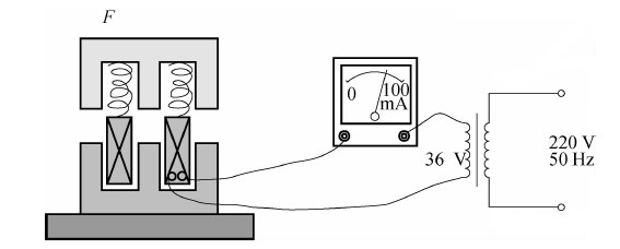
Because AC excitation current flows through the coil, the armature experiences constant electromagnetic attraction, which can cause vibration and introduce additional measurement errors. External interference, power supply voltage and frequency variations, and temperature changes can also cause output errors.
In practice, two identical sensor coils often share one armature to form a differential self-inductance sensor, with both coils having identical electrical parameters and geometric dimensions.
This differential structure not only improves linearity and sensitivity but also compensates for the influence of temperature changes and power supply frequency variations, thereby reducing errors caused by external factors and providing superior performance.
A. Structure of Differential Self-Inductance Sensor

(a) Variable air gap type; (b) Variable-area type; (c) Solenoid type differential self-inductance sensor
B. Features of Differential Self-Inductance Sensor
The differential air gap inductance sensor comprises two identical inductance coils (1, 2) and their associated magnetic circuits.
During measurement, the armature connects to the measured displacement through the measuring rod. When the measured object moves up and down, the guide rod drives the armature to move with the same displacement, causing equal but opposite changes in the magnetic reluctance of the two magnetic circuits. This results in one coil's inductance increasing while the other decreases, forming a differential configuration that doubles the sensitivity and improves linearity.
The characteristic curve of the self-inductance coefficient is shown in the figure below.
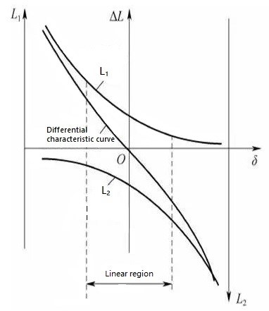
Self-inductance characteristic curve
2 Differential Transformer Type Sensor (LVDT)
The sensor that converts measured non-electrical quantity changes into mutual inductance changes between coils is called a mutual inductance sensor. This sensor operates on the fundamental principle of transformers, converting measured displacement into changes in mutual inductance between primary and secondary coils.
When the primary coil is connected to an excitation power source, the secondary coil generates an induced electromotive force. When the mutual inductance between the coils changes, the induced electromotive force changes accordingly. Because two secondary coils use a differential connection method, it is called a differential transformer type sensor, commonly referred to as a Linear Variable Differential Transformer (LVDT).
1) Structure of the Differential Transformer
There are many types of differential transformers, including variable gap type, variable area type, and solenoid type configurations.
The differential transformers shown in structures A and B are plate-shaped designs with high sensitivity but narrow measuring range, typically used to measure mechanical displacements from several micrometers to several hundred micrometers.

(a) and (b) Variable gap differential transformer
For measuring displacements between 1mm and hundreds of millimeters, cylindrical armature solenoid type differential transformers are commonly used, as shown in structures C and D.
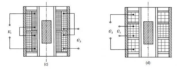
(c) and (d) Solenoid differential transformers
Structures E and F are rotary differential transformers that measure angular displacement, capable of detecting minute angular changes of a few arc seconds. For non-electrical measurements, the solenoid type differential transformer is most commonly used. It can measure a wide range of mechanical displacements with high measurement precision, excellent sensitivity, simple structure, and reliable performance.
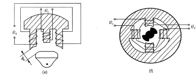
(e), (f) Rotary variable differential transformer
2) Working Principle of the Differential Transformer
The differential transformer structure consists of a core, armature, and coils. While it has many structural forms, the operating principle remains fundamentally the same.
The differential transformer contains one primary coil and two secondary coils in the upper and lower cores. The primary coils are connected in series with an AC excitation voltage, and the two secondary coils are connected in series opposition (reverse polarity connection).
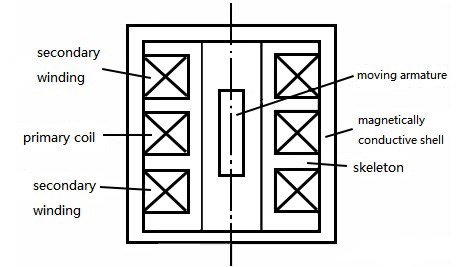
Schematic diagram of three-stage solenoid differential transformer
Two secondary windings with identical numbers of turns are connected in reverse series. When excitation voltage is applied to the primary windings, induced potential is generated in both secondary windings according to the principle of transformer action.
When the movable armature is at the initial equilibrium position (null position), the output voltage is zero if the transformer structure is perfectly symmetrical.
When the movable armature moves toward one secondary coil, the magnetic flux in that secondary coil increases, causing its induced potential to increase while the other decreases. The differential transformer produces an output voltage whose magnitude reflects the displacement of the movable armature, and whose phase indicates the direction of displacement.
The output voltage curve of the three-stage solenoid differential transformer is shown in the figure below.
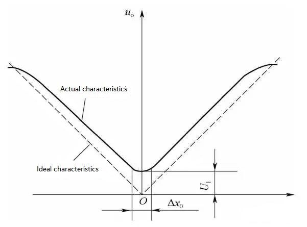
Output voltage curve of the differential transformer
3 Eddy Current Sensor
1) Structure of Eddy Current Sensor
The eddy current sensor has a simple structure, primarily consisting of a flat circular coil arranged within a probe housing. Modern designs often incorporate advanced materials and shielding to improve performance and reduce interference.
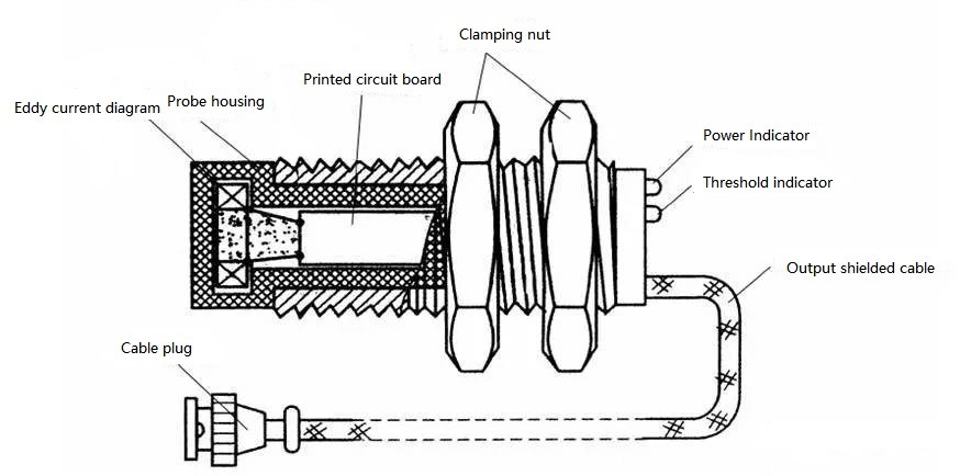
The internal structure of the eddy current sensor
2) Working Principle of Eddy Current Sensor
According to Faraday's law of electromagnetic induction, when a conductive material is placed in a changing magnetic field, induced currents in the form of vortices (called eddy currents) are generated within the conductor. This phenomenon is known as the eddy current effect.
The eddy current sensor utilizes the eddy current effect to convert non-electrical quantities such as displacement, thickness, temperature, and conductivity into changes in impedance or inductance, thereby enabling measurement of these quantities.
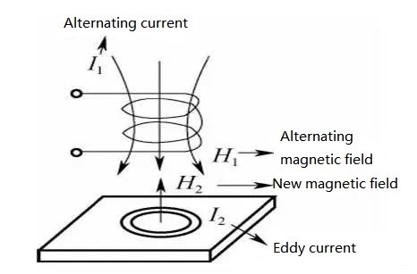
Schematic diagram of eddy current sensor
When a conductive material is placed within the magnetic field of a sensor coil carrying alternating current, according to Faraday's law of electromagnetic induction, the changing current produces an alternating magnetic field around the coil. When the test conductor is placed within range of this magnetic field, eddy currents are induced in the test conductor. These eddy currents produce their own magnetic field, which opposes and partially cancels the original magnetic field, leading to changes in the coil's inductance, resistance, and quality factor. The magnitude of these changes depends on the distance between the sensor and the conductor, as well as the conductor's material properties.
Ⅲ Features of the Inductive Sensor
1. Advantages of the Inductive Sensor
(1) Simple and reliable structure: No moving electrical contacts, resulting in long service life and minimal maintenance requirements.
(2) High sensitivity: Strong output signal with voltage sensitivity reaching hundreds of millivolts per millimeter. The highest resolution can achieve 0.01μm in modern precision applications.
(3) High measurement accuracy: Output linearity can reach ±0.05% to ±0.1% in well-designed systems.
(4) Relatively large output power: In some cases, can be directly connected to secondary instruments without amplification.
(5) High resolution: Capable of detecting minute mechanical displacements and small angular changes.
(6) Good repeatability and linearity: Within a specified displacement range, output characteristics exhibit good linearity and stable output.
(7) Non-contact measurement capability: Especially with eddy current sensors, allowing measurement without physical contact with the target.
(8) Robust and durable: Can operate in harsh environments including high temperatures, vibration, and contaminated conditions.
2. Disadvantages of the Inductive Sensor
(1) Limited frequency response: Not suitable for very fast dynamic measurements, though modern designs have improved this limitation.
(2) Excitation power requirements: Requires stable frequency and amplitude of the excitation power supply for accurate measurements.
(3) Resolution-range trade-off: The sensor's resolution is inversely related to the measurement range. Larger measurement ranges result in lower resolution, and vice versa.
(4) AC zero signal presence: Requires demodulation circuitry, making them less suitable for certain high-frequency dynamic measurements.
(5) Environmental sensitivity: Performance can be affected by nearby metallic objects and electromagnetic interference, requiring proper shielding and calibration.
Ⅳ Application of Inductive Sensor
As a critical tool for data collection and information acquisition, sensors play an essential role in automatic detection and quality monitoring systems. Inductive sensors can convert geometric changes of non-electrical physical quantities—such as length, inner diameter, outer diameter caused by displacement, vibration, and pressure—into minute electrical signal changes. These electrical signals are then converted into measurable electrical parameters. Inductive sensors are high-sensitivity devices featuring simple structure, reliability, substantial output power, strong impedance resistance capability, good stability, and numerous other advantages, making them widely used in various engineering quantity detection and automatic control systems.
Industrial Applications:
1. Precision Manufacturing: Using inductive displacement sensors to improve bearing manufacturing precision; measuring micro-precision dimensional changes with inductance micrometers; accurate measurement of hydraulic valve opening positions.
2. Textile Industry: Flexible sensors for intelligent textile design and quality control.
3. Quality Control: Aperture and taper error measuring instruments based on inductance sensor principles.
4. Predictive Maintenance: Using inductive sensors to detect abrasive particles in lubricating oil for condition monitoring.
5. Material Handling: Monitoring spreader guide wheels and conveyor systems.
Automotive and Transportation:
Inductive sensors serve as magnetic speed switches for gear tooth speed measurement, chain conveyor belt speed and distance detection, gear counting tachometers, and automotive safety system control. They are extensively used in engine management systems, anti-lock braking systems (ABS), and electronic stability control (ESC) systems.
Automation and Robotics:
These sensors are employed for small and medium-sized object detection, object ejection control, wire break monitoring, small parts area division, thickness detection, and position control in feeding tube systems. Modern robotic systems use inductive sensors for precise position feedback and collision detection.
Aerospace and Defense:
LVDTs are used in aircraft control systems, landing gear position sensing, and missile guidance systems due to their reliability and ability to operate in extreme conditions.
Inductive displacement sensors utilize specially wound wire coils. According to displacement changes, the coil's self-inductance or mutual inductance changes, enabling displacement measurement. Based on their conversion principle, inductive displacement sensors are classified into two categories: self-inductance type and mutual inductance type.
The inductive displacement sensor is an electromechanical conversion device widely used in modern industrial production, science, and technology, especially in motion control systems, machining, and measurement industries. Modern applications have expanded to include IoT devices, smart manufacturing systems, and Industry 4.0 implementations.
Ⅴ Modern Developments and Future Trends
Digital Integration: Modern inductive sensors increasingly incorporate digital signal processing (DSP) and microcontroller-based electronics, enabling smart features such as self-calibration, temperature compensation, and digital communication protocols (IO-Link, CANopen, EtherCAT).
Miniaturization: Advances in materials and manufacturing techniques have enabled the development of miniature inductive sensors for applications in medical devices, consumer electronics, and micro-robotics.
Enhanced Performance: Modern sensors feature improved temperature stability (operating ranges from -40°C to +200°C), higher frequency response (up to several kHz), and better immunity to electromagnetic interference through advanced shielding and filtering techniques.
Wireless Capabilities: Integration with wireless communication technologies enables remote monitoring and data collection in Industry 4.0 and IIoT (Industrial Internet of Things) applications.
Multi-axis Sensing: Development of multi-axis inductive sensors capable of simultaneously measuring displacement in multiple directions, reducing system complexity and cost.
Ⅵ Frequently Asked Questions (FAQs)
Q1: What is the typical measurement range of inductive sensors?
A: The measurement range varies by sensor type. Variable gap sensors typically measure 0.01mm to 10mm, solenoid-type LVDTs can measure from 1mm to 500mm, and eddy current sensors typically operate from 0.5mm to 80mm depending on the target material and probe size.
Q2: How do temperature changes affect inductive sensor accuracy?
A: Temperature changes can affect coil resistance, magnetic properties of core materials, and mechanical dimensions. Differential configurations and modern temperature compensation techniques minimize these effects. High-quality sensors maintain accuracy within ±0.1% over their specified temperature range.
Q3: Can inductive sensors detect non-metallic objects?
A: Standard inductive sensors require metallic or conductive targets. However, self-inductance and LVDT types can detect non-metallic objects if they are attached to a metallic armature or core. Eddy current sensors specifically require conductive materials.
Q4: What is the typical frequency response of inductive sensors?
A: Traditional inductive sensors have frequency responses from DC to several hundred Hz. Modern designs with optimized electronics can achieve responses up to 10 kHz, though this varies with sensor type and measurement range.
Q5: How do I choose between LVDT and eddy current sensors?
A: LVDTs are ideal for contact measurements requiring high accuracy, long-term stability, and operation in harsh environments. Eddy current sensors are preferred for non-contact measurements, high-speed applications, and when measuring conductive targets. LVDTs generally offer better linearity and repeatability, while eddy current sensors provide faster response times.
Q6: What maintenance do inductive sensors require?
A: Inductive sensors require minimal maintenance due to their contactless or minimal-contact design. Regular checks should include verifying electrical connections, ensuring proper alignment, cleaning sensor surfaces (especially for eddy current types), and periodic calibration verification. LVDTs with physical contact may require occasional inspection of the core guidance system.
Q7: Are inductive sensors suitable for explosive environments?
A: Yes, intrinsically safe versions of inductive sensors are available with appropriate certifications (ATEX, IECEx) for use in hazardous locations. These sensors are designed with energy-limiting circuits to prevent ignition of flammable atmospheres.
Related Articles:
LVDT Linear Variable Differential Transformer Basics
RVDT Rotary Variable Differential Transformer Basics
Article Last Updated: October 31, 2025
This article has been updated to reflect current technology standards, modern applications, and recent developments in inductive sensor technology. Information includes advances in digital integration, miniaturization, enhanced performance specifications, and expanded application areas including Industry 4.0 and IoT implementations.
 UTMEL
UTMEL
We are the professional distributor of electronic components, providing a large variety of products to save you a lot of time, effort, and cost with our efficient self-customized service. careful order preparation fast delivery service
How does an inductive sensor work?
Inductive sensors use currents induced by magnetic fields to detect nearby metal objects. ... If a target nears the field will induce eddy currents. These currents consume power because of resistance, so energy is in the field is lost, and the signal amplitude decreases.
What is the working principle of inductive proximity sensor?
Inductive Proximity Sensors detect magnetic loss due to eddy currents that are generated on a conductive surface by an external magnetic field. An AC magnetic field is generated on the detection coil, and changes in the impedance due to eddy currents generated on a metallic object are detected.
What can an inductive proximity sensor detect?
Inductive proximity sensors can only detect metal targets. They do not detect non-metal targets such as plastic, wood, paper, and ceramic. Unlike photoelectric sensors, this allows a inductive proximity sensor to detect a metal object through opaque plastic.
What is the difference between capacitive and inductive sensors?
Inductive sensors use a magnetic field to detect objects. Capacitive sensors use an electric field. ... A capacitive sensor will react to an object acting as a dielectric material as well as a conductive object. This makes metal and non-metal objects suitable targets.
What is an inductive sensor used for?
An Inductive sensor is used to measure position . They are usually used within harsh environments as they are generally robust and can deliver stable signals even in hostile environments.
 The Key Role of Electronic Components in IoT DevicesUTMEL01 September 20235774
The article discusses the pivotal role of electronic components in Internet of Things (IoT) devices. IoT devices work by capturing real-world data using sensors, processing it through a microcontroller, and then sending it to the cloud for further analysis.
Read More How to Identify the Perfect Proximity Sensor for Your ApplicationUTMEL19 July 20251688
Find the best proximity sensors for your project by evaluating material, sensing range, environment, and system needs to ensure optimal performance and reliability.
Read More Trusted Vibration Sensors for Homeowners and Industry ProfessionalsUTMEL17 July 20251336
Compare top vibration sensors for home and industrial use. Find trusted options for security, predictive maintenance, and equipment protection.
Read More Wiring and Mounting Photoelectric Sensors in 2025UTMEL15 July 20251538
Wire and mount photoelectric sensors in 2025 with step-by-step safety, wiring, and alignment tips for reliable installation and optimal sensor performance.
Read More Essential Tips for Picking the Best Gas SensorUTMEL15 July 20252908
Find out how to select gas sensors by matching target gases, environment, and compliance needs for reliable and accurate gas detection in any setting.
Read More
Subscribe to Utmel !
![35002]() 35002
35002Lapp
![EPM80LC650]() EPM80LC650
EPM80LC650Menda
![04640]() 04640
04640Schneider
![EK60WV031]() EK60WV031
EK60WV031Menda
![EBW608]() EBW608
EBW608Menda
![A 10 -32]() A 10 -32
A 10 -32Phoenix Contact
![A 10 -25]() A 10 -25
A 10 -25Phoenix Contact
![A1050]() A1050
A1050interlight
![ETM60CP302]() ETM60CP302
ETM60CP302Menda
![EPM75BS602]() EPM75BS602
EPM75BS602Menda