Product
 Brand
Brand Articles
 Tools
Tools
Pulse Sensor-Definition, Working and Applications
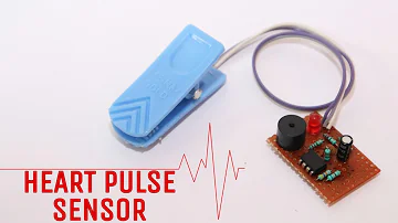
Heart Pulse sensor | how to make heart pulse sensor at home
Catalog
Ⅰ What is a pulse sensor?
Knowing the heartbeat rate data is very convenient when performing fitness, learning, etc. But, it can be difficult to measure the pulse rate. The pulse sensor or heartbeat sensor is used to solve this problem. This is a plug & play sensor specifically developed for Arduino boards that can be used in their projects by designers, students, engineers, artists who can use the heartbeat data. In order to create a circuit, this sensor uses an easy optical pulse sensor along with amplification & noise cancellation. We can get fast and accurate heartbeat readings by the use of this circuit. This circuit can be used in mobile applications with a 4mA current and a 5V voltage.
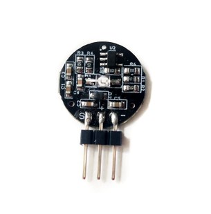
pulse sensor
A 24-inch color code wire, ear lock, Velcro Dots-2, clear stickers-3, etc. are part of the pulse sensor.
To the header connectors, a color code cable is attached. So, without soldering, this sensor is conveniently attached to an Arduino in the project.
The size of an ear clip is the same as a heart rate monitor, and it can be attached to the earlobe using hot glue on the back of the sensor.
On the hook line, two Velcro dots are completely dimensioned against the sensor. These are particularly helpful for designing a Velcro band to protect a fingertip or so. This is used around the finger to protect the sensor.
Protection layers used to shield the sensor from moist earlobes and fingertips are translucent batters. In the area of the external side, this sensor has three holes such that something can be conveniently attached to it.
Ⅱ How do pulse sensors work?
The Pulse/Heart Beat Sensor is very quick to use. The sensor has two sides, the LED is mounted with an ambient light sensor on one side, and we have some circuitry on the other side. The amplification and noise cancellation work are responsible for this circuitry. In our human body, the Lead on the front side of the sensor is positioned over a vein. This may be the tip of your finger or the tip of your lip, so it should be positioned directly on top of a vein.
The LED now releases light that would fall straight into the vein. Only while the heart is beating would the veins have blood pressure within them, so we can track the heartbeats as well if we monitor the blood flow. When the blood pressure is observed, the ambient light sensor will gather more light so the blood will reflect it, this small difference in the light collected will be measured over time to calculate our heartbeats.
Ⅲ How to use pulse sensors?
It is straightforward to use the pulse sensor, but it matters to put it in the right way. It is also advised to cover the sensor with hot glue, vinyl tape or other non-conductive materials because all the electronics on the sensor are directly exposed. Manipulating these sensors with wet hands is also not advised. In order to meet this pressure, the flat side of the sensor should be put on top of the vein and a small presser should be added on top of it, usually, clips or Velcro tapes are used.
The sensor will work both at + 5V or 3.3V device to simply control it using the Vcc and ground pins to use the sensor. To watch the shift in output voltage, link the signal pin to the ADC pin of the microcontroller once powered. If you use a programming board like Arduino, you will use the coding that is readily accessible, which can make it even simpler.
Use of pulse sensor Arduino
This sensor is used directly, but it is necessary to attach it in the correct way. Since all kinds of electronic parts are exposed to the sensor directly. Therefore, by using hot glue, vinyl strip, or other forms of non-conductive fabrics, it is necessary to envelop this sensor.
It is not possible to control such sensors with wet hands. The smooth side of the sensor must be positioned & pressed on the apex of the vein. Generally, to get this power, Velcro tapes or clips are used.
By attaching it to the Arduino frame, this sensor can be used. Then send the power supply with the aid of VCC pin and GND pins until it is attached. This sensor's working voltage is +5V or 3.3V. Once the sensor is attached to the development board, such as Arduino, we can make it simpler by using the readily available Arduino code. Please link to the Arduino Pulse Sensor Interfacing Site for Arduino and its coding.
Ⅳ Applications of Pulse Sensor
Generally, it is possible to calculate the arterial blood oxygen saturation by looking at the time of fluctuation from the waveform obtained from measurements of the pulse wave sensor and observing the pulsation (variation) using the heart rate along with both red and infrared waves (SpO2).
In addition, by high-speed sampling and high precision measurement, the use of data from pulse sensors is expected to enable the estimation of various vital signs such as HRV analysis (stress level) and vascular age. The following are used in the pulse rate sensor implementations.
Sleep Tracking
Anxiety monitoring
Remote patient monitoring or alarm system
Health bands
Complex gaming consoles
This is all about the Heartbeat / Heartrate Monitor (pulse sensor). The hardware is open-source and plug-and-play. This sensor will quickly integrate knowledge about live heartbeats into their designs. This sensor comprises two circuits, such as an optical amplifier and a noise eliminator. Otherwise, a clip may be used to attach this sensor to the earlobe fingertip and bind it to the Arduino board. This makes it easier to test the heart rhythm. Developers, teachers, designers, performers, musicians, etc. use these sensors.
 UTMEL
UTMEL
We are the professional distributor of electronic components, providing a large variety of products to save you a lot of time, effort, and cost with our efficient self-customized service. careful order preparation fast delivery service
1.How does a pulse sensor work?
Transmission types measure pulse waves by emitting red or infrared light from the body surface and detecting the change in blood flow during heart beats as a change in the amount of light transmitted through the body. This method is limited to areas where light can easily penetrate, such as the fingertip or earlobe.
2.What is the use of a pulse sensor?
Pulse Sensor is a well-designed plug-and-play heart-rate sensor for Arduino. It can be used by students, artists, athletes, makers, and game & mobile developers who want to easily incorporate live heart-rate data into their projects.
3.What is the sensor for heart rate?
The infrared sensor is responsible for sending infrared light to the body. This sensor has a pair of transmitter and receiver. Using photodiode can also detect reflective light from the body and this signal is sent to the microcontroller to detect the heartbeat.
4.How do you test a heart rate sensor?
At the wrist, lightly press the index and middle fingers of one hand on the opposite wrist, just below the base of the thumb. At the neck, lightly press the side of the neck, just below your jawbone. Count the number of beats in 15 seconds, and multiply by four. That's your heart rate.
5.What is the difference between optical and electrical heart sensors?
The optical heart sensor supports a range of 30–210 beats per minute. To use the electrical heart sensor to measure your heart rate, open the Heart Rate app and place your finger on the Digital Crown. You will get a faster reading with higher fidelity — getting a measurement every second instead of every 5 seconds.
 The Key Role of Electronic Components in IoT DevicesUTMEL01 September 20235778
The article discusses the pivotal role of electronic components in Internet of Things (IoT) devices. IoT devices work by capturing real-world data using sensors, processing it through a microcontroller, and then sending it to the cloud for further analysis.
Read More Accelerometer Sensors Guide: Working Principle, Circuit Design, Specifications, and ApplicationsUTMEL25 June 202684
A practical accelerometer sensor guide covering working principles, MEMS and piezoelectric types, datasheet specifications, circuit design, mounting, applications, and selection.
Read More How to Identify the Perfect Proximity Sensor for Your ApplicationUTMEL19 July 20251691
Find the best proximity sensors for your project by evaluating material, sensing range, environment, and system needs to ensure optimal performance and reliability.
Read More Trusted Vibration Sensors for Homeowners and Industry ProfessionalsUTMEL17 July 20251339
Compare top vibration sensors for home and industrial use. Find trusted options for security, predictive maintenance, and equipment protection.
Read More Wiring and Mounting Photoelectric Sensors in 2025UTMEL15 July 20251540
Wire and mount photoelectric sensors in 2025 with step-by-step safety, wiring, and alignment tips for reliable installation and optimal sensor performance.
Read More
Subscribe to Utmel !