
 Product
 Brand
Brand Articles
 Tools
Tools
Comparison of Advantages and Disadvantages of Common Switch Mode Power Supply(SMPS)
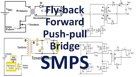
SMPS Fly-bacK, Forward, Push-Pull, Bridge Topology#All about Switch Mode Power Supply#
| Topics covered in this article: |
| Ⅰ. The basic pulse width modulation waveform |
| Ⅱ. The common basic topology |
| Ⅲ. Details of circuit work |
| Ⅳ. Summary |
Ⅰ. The basic pulse width modulation waveform
All of these topologies have something to do with switching circuits. The following is the definition of a basic PWM waveform:

Ⅱ. The common basic topology
1. Buck

Reduce the voltage of the input to a lower level. Probably the most straightforward circuit. After switching, the inductor/capacitor filter smooths out the square wave. In every case, the output is less than or equal to the input. The input current is irregular (chopped). The output current is smooth.
2. Boost

Increase the voltage of the input. Same as buck, but with inductors, switches, and diodes rearranged. In every case, the output is more than or equal to the input (ignoring diode forward drop). The input current has been softened. The output current is irregular (chopped).
3. Buck-Boost

A different configuration of inductors, switches, and diodes. Combination of the drawbacks of buck and boost circuits. The input current is irregular (chopped). In addition, the output current is not constant (chopping). Although the output is always inverse to the input (due to the polarity of the capacitors ), the magnitude can be smaller or larger. A "flyback" converter is a buck-boost circuit isolation device (transformer coupling).
4. Flyback

The inductor contains two windings and works as both a transformer and an inductor, similar to a buck-boost circuit. Depending on the polarity of the coil and diode, the output can be positive or negative. The turns ratio of the transformer determines whether the output voltage is larger or less than the input voltage. The simplest of the isolation topologies is this one. By adding secondary windings and circuits, you can have many outputs.
5. Forward

The input current is irregular, while the output current is smooth. The output might be larger or less than the input, in any polarity, due to the transformer.
By adding secondary windings and circuits, you can have many outputs. During each switching cycle, the transformer core must be demagnetized. Adding a winding with the same number of turns as the primary winding is a typical practice. The energy accumulated in the primary inductance during the switch-on phase is released during the switch-off phase via extra windings and diodes,
6. Two-Transistor Forward

Both switches are active at the same time. The energy stored in the transformer flips the polarity of the primary when the switch is open, causing the diode to conduct. The voltage on each switch never exceeds the input voltage, and the winding tracks do not need to be reset.
7. Push-Pull

To regulate the output voltage, the switches (FETs) are operated out of phase and pulse-width modulated (PWM). Power is transferred in all half-cycles, indicating good transformer core use. Due to the full-wave topology, the output ripple frequency is twice that of the transformer. The FET is subjected to a voltage that is twice that of the input voltage.
8. Half-Bridge

For higher power converters, this is a relatively frequent topology. To modify the output voltage, the switches are operated out of phase and pulse width modulated. Power is transferred in all half-cycles, indicating good transformer core use. The primary winding is also better used than in a push-pull circuit.
Due to the full-wave topology, the output ripple frequency is twice that of the transformer. The input voltage is identical to the voltage applied to the FET.
9. Full-Bridge

For higher power converters, this is the most popular topology. To regulate the output voltage, the switches are powered in diagonal pairs and pulse-width modulated. Power is transferred in all half-cycles, indicating good transformer core use. Due to the full-wave topology, the output ripple frequency is twice that of the transformer. The input voltage is equivalent to the voltage applied to the FETs. The primary current is half that of a half-bridge at a given power,
10. SEPIC single-ended primary inductance converter

The output voltage can be higher or lower than the input. The input current is smooth, just like the boost circuit, but the output current is not. Capacitors transport energy from the input to the output. It is necessary to use two inductors.
11. C'uk (patent of Slobodan C'uk)

In this case, the output is inverted. The output voltage can be more or lesser than the input voltage. The input and output currents are both smooth.
Capacitors transport energy from the input to the output. It is necessary to use two inductors. For zero ripple inductor current, inductors can be linked.
Ⅲ. Details of circuit work
The working details of several topologies are explained below.
1. Buck-buck regulator-continuous conduction

The current in the inductor is constant. The average value of its input voltage is Vout (V1). The output voltage is equal to the input voltage multiplied by the switch's duty ratio (D). The inductor current flows from the battery when it is turned on. When the switch is open, the current passes through the diode. D is independent of load current when losses in switches and inductors are taken into account. Buck regulators and their derivatives have a constant output current and a discontinuous input current (chopping) (smoothing).
2. Buck-buck regulator-critical conduction

The inductor current is still continuous; when the switch is turned on again, it "reaches" zero. This is referred to as "critical conduction." The output voltage is still equal to D times the input voltage.
3. Buck-buck regulator-discontinuous conduction

The current in the inductor is 0 for a portion of each cycle in this situation. The average of v1 is still (always) the output voltage. The output voltage is not equal to the input voltage multiplied by the switch's duty ratio (D). D fluctuates with the load current when the load current is below the critical threshold (while Vout remains constant).
4. Boost regulator

The output voltage is always higher (or equal to) than (or the same as) the input voltage. The input current is constant, whereas the output current is variable (as opposed to a buck regulator). In contrast to a buck regulator, the relationship between the output voltage and duty ratio (D) is not as straightforward. In the event of continuous conduction, the following is true:

Vin = 5, Vout = 15, D = 2/3 in this example. D = 2/3, Vout = 15.
5. Transformer work (including the role of primary inductance)

The primary (magnetizing) inductance of a transformer is considered parallel to the primary in an ideal transformer.
6. Flyback transformer

The peak current and stored energy are calculated using the primary inductance, which is low in this case.
7. Forward Transformer

Because there is no need to store energy, the primary inductance is high. After the primary switch is turned off, the magnetizing current (i1) flows into the "magnetizing inductance," causing the core to demagnetize (voltage reversal).
Ⅳ. Summary
This article examines the most prevalent switching power conversion circuit topologies currently in use. There are many more topologies, but the majority are combinations or modifications of these. Each topology has its own set of design considerations, such as the voltage provided to switches, the chopping and smoothing of input and output currents, and the winding consumption. Research is required to determine the optimal topology: input and output voltage ranges, current ranges, cost and performance, and size and weight ratios.
 UTMEL
UTMEL
We are the professional distributor of electronic components, providing a large variety of products to save you a lot of time, effort, and cost with our efficient self-customized service. careful order preparation fast delivery service
1. What is a switching power supply?
Switch mode power supply, also known as switching power supply and switching converter, is a high-frequency power conversion device and a type of power supply. Its function is to convert a level of voltage into the voltage or current required by the user through different forms of architecture.
2. What is the difference between switching power supply and DC regulated power supply?
1. Different nature
(1). DC stabilized power supply: an electronic device that can provide a stable DC power supply for the load.
(2). Switching power supply: It is a high-frequency electric energy conversion device.
2. Different uses
(1). Application of DC regulated power supply:
DC regulated power supply is widely used in national defense, scientific research, laboratory and so on.
(2). Application of switching power supply:
Switching power supply products are widely used in industrial automation control, military equipment, scientific research equipment and other fields.
3. What do the G and NC on the switching power supply mean?
G means GND on the circuit diagram and on the board stands for the ground or 0 wire. GND means the common terminal, it can also be said to be the ground, but this ground is not the ground in the real sense, it is a ground assumed for the application, for the power supply, it is the negative pole of a power supply. It is different from the earth. NC means "no connection".
 LLC Converter with Planar Matrix Transformer for High-Current-High-Power ApplicationsSaumitra Jagdale15 March 20244769
The rise of data centres in recent years, driven by cloud computing and big data, has caused a significant increase in electricity consumption. In the United States alone, it exceeded 70 billion kWh by 2014, making up 1.8% of total national electricity usage.
Read More Enhancing Frequency Stability in Modern Distributed Power SystemsRakesh Kumar, Ph.D.21 September 20244263
The article discusses the importance of primary frequency regulation in maintaining grid stability. It also explores battery energy storage systems, virtual synchronous generators, and advanced control strategies to enhance frequency stability in power systems.
Read More The Impact of SMPS on LED Lighting and Diverse IndustriesUTMEL05 June 20252622
Switched-Mode Power Supplies (SMPS) enhance LED lighting and industries by improving energy efficiency, reliability, and sustainability across diverse applications.
Read More?") What is Uninterruptible Power Supply (UPS)?UTMEL08 April 20215276
What is Uninterruptible Power Supply (UPS)?UTMEL08 April 20215276UPS is an uninterruptible power supply containing the energy storage device. It is mainly used to give a part of a device with a higher power stability, providing uninterrupted power supplies.
Read More Switch-mode Power Supply BasicsUTMEL14 December 20207889
Switched-mode Power Supply (SMPS), also known as switching converter, is a high-frequency electric energy conversion device and a type of power supply. Its function is to convert a level of voltage into the voltage or current required by the user through different forms of architecture.
Read More
Subscribe to Utmel !
![LY4F-DC48]() LY4F-DC48
LY4F-DC48Omron Automation and Safety
![2904-05-421]() 2904-05-421
2904-05-421Coto Technology
![LY4F-AC100/110]() LY4F-AC100/110
LY4F-AC100/110Omron Automation and Safety
![LY3-0-DC12]() LY3-0-DC12
LY3-0-DC12Omron Automation and Safety
![G6K-2F-RF-TR03DC5]() G6K-2F-RF-TR03DC5
G6K-2F-RF-TR03DC5Omron Electronics Inc-EMC Div
![RH1B-UAC240V]() RH1B-UAC240V
RH1B-UAC240VIDEC
![HE2AN-DC24V]() HE2AN-DC24V
HE2AN-DC24VPanasonic Electric Works
![DSP1A-DC24V-R]() DSP1A-DC24V-R
DSP1A-DC24V-RPanasonic Electric Works
![NC2D-JP-DC12V]() NC2D-JP-DC12V
NC2D-JP-DC12VPanasonic Electric Works
![2900312]() 2900312
2900312Phoenix Contact


