
 Product
 Brand
Brand Articles
 Tools
Tools
An Overview of Thermal Overload Relays

overload relay working principle
Catalog
VIII Causes of No-action or Malfunction
| |
I What is Thermal Overload Relay?
Thermal overload relays are protective electrical appliances used for overload protection of motors or other electrical equipment and electrical circuits.
The thermal overload relay is mainly used for the overload protection of asynchronous motors. Its working principle is:
after the overload current passes through the thermal element, the bimetallic sheet is heated and bent to push the action mechanism to drive the contact, thereby disconnecting the motor control circuit to shut the motor down with the power off, playing the role of overload protection. For the heat transfer takes a long time during the heating and bending of the bimetallic sheet, the thermal overload relay cannot be used for short-circuit protection, but can only be used for overload protection.
Thermal overload relay has been widely used as the overload protection component of the motor, due to its small size, simple structure, and low cost.
II Composition of Thermal Overload Relays
The thermal overload relay is composed of a bimetallic sheet, heating element, action mechanism, and contact system. The bimetal sheet is made by welding two layers of metal sheets with a large difference in expansion coefficient. When in use, the heating element is connected in series with the motor power supply, and the contact is connected in series in the contactor coil control circuit.
When the motor is overloaded, the current is large, which causes the bimetallic sheet to be heated and bend. And through the action mechanism, the moving contact and the static contact are disconnected, so that the contactor coil is de-energized and the motor is disconnected from the power supply.

Figure 1. Structure of Thermal Overload Relay
(1) Bimetallic sheet: Bimetallic sheet is the most critical part of the thermal overload relay. It combines two metal sheets with different linear expansion coefficients by mechanical rolling.
At room temperature (that is, before heating), the whole is usually flat, as shown in Figure 2(a). When the temperature rises, metal sheet 1 (called the active layer) with a large linear expansion coefficient tries to make a larger extension, while metal sheet 2 with a small linear expansion coefficient (called the driven layer) can only make a smaller extension. Because the two layers of materials are tightly attached and cannot be extended freely, the bimetallic sheet changes from a flat state to a bent state, as shown in Figure 2(b). So the active layer can extend a bit more and the driven layer extends less. This is the reason why the bimetallic sheet can produce bending deformation after being heated.
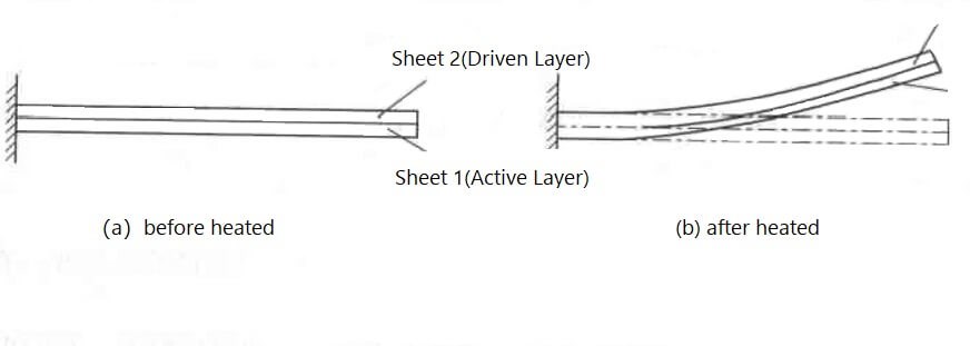
Figure 2. Working Principle of Bimetallic Stripe
(2) Heating element: The heating element is generally made of copper-nickel alloy, nickel-chromium alloy or chromium-aluminum alloy, etc., and its shape is a filament, sheet or ribbon, etc. Its function is to use the thermal effect generated when the electric currents pass through the resistance heating element to drive the sensing element to move.
(3) Control contacts, action coefficients control contacts, and action systems or action mechanisms. Most of them use bow spring type, compression spring type or Lafee jumping mechanism. The action system is often equipped with a temperature compensation device to ensure that the operating characteristics of the thermal overload relay remain basically unchanged within a certain temperature range.
(4) Reset mechanism: There are manual reset and automatic reset, which can be adjusted freely according to the requirements of use.
III Thermal Overload Relay Classification
According to the number of phases, there are three types of thermal overload relays: single-phase thermal overload relays, two-phase thermal overload relays, and three-phase thermal overload relays. Each type has different specifications and models according to the rated current of the heating element. Three-phase thermal overload relays are often used in three-phase AC motors for overload protection.
According to their functions, three-phase thermal overload relays have two types: the types without phase protection and the types with phase protection.
IV Performance of Thermal Overload Relays
1. Protection Characteristics
Because the contact action time of the thermal overload relay is related to the overload degree of the protected motor, before analyzing the working principle of the thermal overload relay, we must first clarify the relationship between the motor's overload current and the motor energizing time when the allowable temperature rise is not exceeded. This relationship is called the overload characteristic of the motor.
When an overload current occurs during the operation of the motor, it will inevitably cause the winding to heat up. According to the thermal balance relationship, it is not difficult to conclude that the conduction time of the motor is inversely proportional to the square of its overload current under the allowable temperature rise:
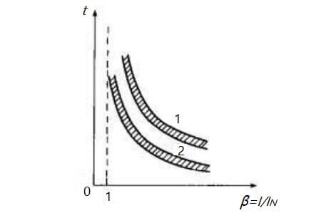
Figure 3. Relationship Between Conduction Time and Overload Current
In order to adapt to the overload characteristics of the motor and play the role of overload protection, the thermal overload relay is required to have inverse time characteristics. For this reason, a resistance heating element must be provided in the thermal overload relay. Thus the thermal effect generated by the overload current through the resistance heating element is used to make the sensing element act, thereby driving the contact action to complete the protection.
The relationship between the overload current passing through the thermal overload relay and the action time of the thermal overload relay contact is called the protection characteristic of the thermal overload relay, as shown in curve 2 in Figure 3. Considering the influence of various errors, the overload characteristic of the motor and the protection characteristic of the relay is not one curve, but a strap. Obviously, the greater the error, the wider the strap; the less the error, the narrower the strap.
It can be seen from curve 1 in the figure that when the motor is overloaded, it is safe to work under curve 1. Therefore, the protection characteristics of the thermal overload relay should be adjacent to the motor overload characteristics. In this way, if an overload occurs, the thermal overload relay will act before the motor reaches its allowable overload limit to cut off the motor's power supply to prevent damage.
2. Other Basic Performances
(1) Control Contact
The normally open and normally closed contacts of the thermal overload relay should be able to operate the coil circuit of the AC contactor more than 1000 times under the specified operating current.
(2) Ampere-second Characteristics
This is also called the current-time characteristic, which represents the relationship between the operating time and the passing current of the thermal overload relay, and is usually an inverse time characteristic. In order to reliably realize the overload protection of the motor, the ampere-second characteristic of the thermal overload relay should be lower than the allowable overload characteristic of the motor.
(3) Current Adjustment
The current adjustment range of thermal overload relays is generally from 66% to 100%, and the maximum is from 50% to 100%.
(4) Temperature Compensation
In order to reduce the action error caused by the environmental temperature change, temperature compensation measures should be taken.
(5) Reset time
The automatic reset time of the thermal overload relay should be no more than 5min, and the manual reset time should be no more than 2min.
(6)Thermal Stability
Thermal stability is the ability to withstand overload current. The thermal stability requirements for the thermal element are: at the maximum setting current, 10 times the maximum setting current is applied to the rated current of 100A and below, and 8 times the maximum setting current is applied to the setting current above 100A. After, the thermal overload relay should be able to reliably move 5 times.
V Causes of Thermal Overload Relay Tripping
Thermal overload relay tripping is mainly caused by overload or improper selection. The thermal overload relay is used to protect electrical appliances from overload. The design must match the electrical appliances. If the thermal overload relay is too small or the electrical equipment has resistance, the overload will often trip. After the thermal overload relay trips, the contactor will lose power and trip.
Other causes:
(1) The setting value of the thermal overload relay is too small;
(2) The motor load current is too large, there may be a short-circuit fault between turns or the motor transmission part is not flexible;
(3) The quality of the thermal overload relay is not good enough or the contacts are in poor contact.
(4) The quality of the contactor is not good enough or the contacts are in poor contact.
VI How to Reset Thermal Overload Relays after Tripping
There are two ways to reset the thermal overload relay: manual reset and automatic reset.
1. Manual Reset
After the thermal overload relay overload protection action, you must press the reset button by hand to make the normally closed contact return closed. Manual reset should be performed 2-3mins after the tripping because the internal bending heating sheet needs cooling.
2. Automatic Reset
After the thermal overload relay protection action, the normally closed contact is automatically closed, and the time of automatic reset is generally no more than 5min.
The reset method can be selected through the reset adjustment screw.
Put a straight screwdriver into the adjustment hole on the lower side of the thermal overload relay, and tighten the reset adjustment screw clockwise (to the end), which is the automatic reset method. If you loosen the reset adjustment screw counterclockwise, so that the screw is unscrewed a certain distance, and it becomes a manual reset.
The new thermal overload relay generally has an adjustment button on its upper cover. When the adjustment button is turned to H, it is manual reset, and when the adjustment button is turned to A, it is automatical reset.
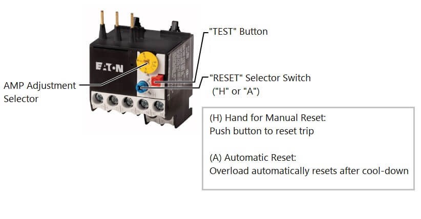
Figure 4. Manual Reset&Automatic Reset
When the thermal overload relay is used for the overload protection of the motor, to ensure that the normally closed contact of the thermal overload relay can be reset and closed after the fault is handled, the thermal overload relay is generally set to the manual reset mode.
VII Precautions for Use
(1) The thermal overload relay can only be used for motor overload and phase failure protection, not for short circuit protection.
(2) The choice of installation point.
● The temperature difference between the installation place of the thermal overload relay and the protected equipment should not be too large;
● There should be no vibration source in the installation point;
● when the thermal overload relay is installed with other electrical appliances, to make its action characteristics not be affected by other heating appliances, it should be installed below.
(3) The installation direction of the thermal overload relay should be the same as specified in the product manual, and the deviation should not exceed 5°.
(4) The connecting wire used for the thermal overload relay should meet the specifications. If the cross-section of the connecting wire is too small, the axial heat transfer is slow, and the thermal overload relay will malfunction. If the connecting wire is too thick, the axial heat conduction is fast, and the thermal overload relay acts slowly or refuses to move.
The material of the wire is generally copper, if aluminum core wire is used, the ends should be tinned.
(5) The binding screws of the thermal overload relay should be tightened, otherwise, the contact resistance and the temperature of the heating element will increase, which will cause the thermal overload relay to malfunction.
(6) The automatic reset thermal overload relay should be adjusted to the automatic position, and it will automatically reset after 3-5min after the protection action. For the manual reset thermal overload relay, the reset button should be pressed after the protection action.
VIII Causes of No-action or Malfunction
The reasons for Inaction or malfunction of thermal overload relay are as follows:
1. Causes of No-action
The cause of the no-action failure of the thermal overload relay may be:
(1) the current setting value is too large;
(2) the thermal element is burned or sealing off;
(3) the action mechanism is stuck or the buckle falls off.
(4) In repairing, the setting current can be adjusted appropriately according to the load capacity, and the thermal element or the action mechanism can be overhauled.
2. Causes of Malfunction
The reasons may be:
(1) the current setting value is too small;
(2) the thermal overload relay is not matched with the load;
(3) the motor starting time is too long or too many times of continual starting;
(4) the line or load is leaking or short-circuited;
(5) the thermal overload relay is subject to strong shock or vibration.
During maintenance, we should find out the causes, and reasonably adjust the setting current or replace a thermal overload relay matched with the load.
If the motor or circuit is faulty, the motor and the power supply circuit should be overhauled; if there are too many vibrations in the working environment, a thermal overload relay with an anti-vibration device should be used.
IX How to Select Thermal Overload Relays
1. In principle, the ampere-second characteristic of the thermal overload relay should be as close as possible or even coincide with the overload characteristic of the motor, or under the overload characteristic of the motor. And at the same time, the thermal overload relay should not be affected (no action) at the moment of short-term overload and startup of the motor.
2. When thermal overload relays are used to protect motors in long-term work or intermittent long-term work, they are generally selected according to the rated current of the motor. For example, the setting value of the thermal overload relay can be equal to 0.95-1.05 times the rated current of the motor, or the median value of the setting current of the thermal overload relay can be equal to the rated current of the motor, and then to adjust.
3. When the thermal overload relay is used to protect the motor with the repeated short-time operation, the thermal overload relay has only a certain range of adaptability. If there are many operations in a short time, a thermal overload relay with a fast saturation current transformer should be used.
4. For the special working motor with positive and reverse rotation and frequent on and off, the thermal overload relay should not be used as an overload protection device but should be protected by a temperature relay or thermistor embedded in the motor winding.
 UTMEL
UTMEL
We are the professional distributor of electronic components, providing a large variety of products to save you a lot of time, effort, and cost with our efficient self-customized service. careful order preparation fast delivery service
1.What is a thermal overload relay?
Thermal overload relays are economic electromechanical protection devices for the main circuit. They offer reliable protection for motors in the event of overload or phase failure. The thermal overload relay can make up a compact starting solution together with contactors.
2.Where are thermal overload relays used?
A thermal overload relay works in the principle of electro-thermal properties in a bimetallic strip. It is placed in the motor circuit in such a way that the current to the motor flows through its poles.
3.What are the different types of thermal overload relay?
There are three types of thermal overload relays — bimetallic, eutectic, and electronic.
4.How does an overload relay thermal unit work?
The thermal overload relay is designed to protect the motor or other load from damage in the event of a short circuit, or being over-loaded and overheating. The simplest overload relay is activated by heat caused from high current flowing through the overload and over a bimetallic strip.
5.What happens if you overload a relay?
Overload relays protect a motor by sensing the current going to the motor. Many of these use small heaters, often bi-metallic elements that bend when warmed by current to the motor. When the current is too high for too long, heaters open the relay contacts carrying current to the coil of the contactor.
 What is Time Delay Relay?UTMEL18 December 202515987
Hello everyone, I am Rose. Today I will introduce Time Relay to you. A Time Relay is an electrical component that is used on a circuit with a lower voltage or lower current to turn on or off a circuit with a higher voltage and bigger current or to regulate a higher voltage or larger power. This article will introduce some basic knowledge of Time Relay.
Read More What is Safety Relay?UTMEL12 April 202525564
Safety relays represent a critical advancement in industrial automation technology, serving as essential components in machine safety systems. Unlike standard relays, safety relays are specifically engineered to provide reliable protection in potentially hazardous environments. This article explores the fundamental aspects of safety relays, including their operational principles, wiring configurations, and proper implementation methods in industrial settings.
Read More What is Relay?UTMEL15 November 20217613
Hello everyone, I am Rose. Welcome back to the new post today. Relay is an autonomous electrical appliance used in electric drive systems for control, protection, and signal conversion. It is suitable for remote connection and disconnection of AC and DC small-capacity control circuits.
Read More AC Contactor: What is Self-Locking?UTMEL01 March 202212259
AC contactors often use three arc extinguishing methods: double-break electric arc extinguishing, longitudinal seam arc extinguishing and grid arc extinguishing. It is used to eliminate the arc generated by the moving and static contacts during the opening and closing process.This article mainly introduce the principle of AC Contactor self-locking.
Read More Weak Current Control Strong Current: How to use the Relay?UTMEL28 November 20226437
Hello everyone, I am Rose. Welcome to the new post today. Today I will introduce relay to you. Including its definition, parameters, working principle and so on.
Read More
Subscribe to Utmel !
![RC1206JR-0747KL]() RC1206JR-0747KL
RC1206JR-0747KLYageo
![ERJ-2RKF4992X]() ERJ-2RKF4992X
ERJ-2RKF4992XPanasonic Electronic Components
![RC0603FR-07121KL]() RC0603FR-07121KL
RC0603FR-07121KLYageo
![CRCW251210R0JNEGHP]() CRCW251210R0JNEGHP
CRCW251210R0JNEGHPVishay Dale
![CRCW08053K01FKEA]() CRCW08053K01FKEA
CRCW08053K01FKEAVishay Dale
![CRCW120615K0FKEA]() CRCW120615K0FKEA
CRCW120615K0FKEAVishay Dale
![RC0805JR-071RL]() RC0805JR-071RL
RC0805JR-071RLYageo
![WSL25122L000FEA18]() WSL25122L000FEA18
WSL25122L000FEA18Vishay Dale
![RC0603FR-0743KL]() RC0603FR-0743KL
RC0603FR-0743KLYageo
![RC0402JR-073K3L]() RC0402JR-073K3L
RC0402JR-073K3LYageo


