
 Product
 Brand
Brand Articles
 Tools
Tools
Basic Introduction to Color Sensor
How the Color Sensor Works
Catalog
Ⅰ What is a Color Sensor and Why is it Important in 2026?
A color sensor is a type of photoelectric sensor that detects and converts light into an electrical signal to identify the color of an object, playing a critical role in modern automated systems. By utilizing an array of internal red (R), green (G), and blue (B) photodetectors, the sensor emulates human eye perception to provide precise color data. In 2026, the demand for color sensors is surging, with the market projected to reach $2.9 billion, driven by advancements in industrial automation, medical diagnostics, and smart electronics [1].
The importance of color sensors in 2026 is tied to their ability to enhance efficiency and accuracy in various fields:
Industrial Automation: In high-speed manufacturing, color sensors are essential for sorting products, verifying packaging, and ensuring color consistency in textiles and paints, which significantly reduces errors and improves quality control.
Medical Technology: Advanced color sensors are used in diagnostic equipment for applications like urine analysis and blood diagnostics, providing rapid and reliable results.
Consumer Electronics: Modern devices, including smartphones and monitors, rely on color sensors for screen calibration and ambient light adjustment, enhancing user experience.
Ⅱ How Does a Color Sensor Work?
A color sensor operates by converting light into a corresponding electrical signal, which is then analyzed to determine the color. Modern color sensors are primarily categorized into three types based on their output: light-to-photocurrent, light-to-analog voltage, and light-to-digital. While the most basic type is the light-to-photocurrent sensor, its low-amplitude signal requires external amplification. As a result, most practical sensors today integrate an amplifier to produce a more usable analog or digital voltage output.
1. How Do Light-to-Photocurrent Sensors Convert Light?
A light-to-photocurrent sensor converts light energy directly into an electrical current using a photodiode, which is a semiconductor p-n junction designed to detect light. When photons strike the photodiode's photosensitive area, they generate electron-hole pairs, creating a photocurrent proportional to the light's intensity. This type of sensor is ideal for applications requiring rapid response times and custom gain adjustments, especially in environments with fluctuating light conditions.
The process involves these key steps:
Photon Absorption: When light enters the photodiode, photons are absorbed, freeing electrons and creating a flow of photogenerated carriers.
Current Generation: Under a reverse-bias voltage, these carriers are swept across the p-n junction, producing a photocurrent that is directly proportional to the incident light intensity.
Signal Conversion: The resulting photocurrent, which is typically very small, is then converted into a usable voltage signal by an external transimpedance amplifier and digitized by an analog-to-digital converter (ADC) for processing by a microcontroller.
2. How Do Light-to-Analog Voltage Sensors Work?
A light-to-analog voltage sensor works by integrating a photodiode array with a transimpedance amplifier on a single chip to directly output a voltage signal proportional to light intensity. This design simplifies the circuitry by eliminating the need for a separate current-to-voltage conversion stage, making it ideal for applications that demand faster design cycles and efficient space utilization.
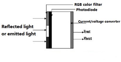
Light-to-analog voltage sensor diagram
The key operational features include:
Integrated Amplification: The sensor combines a photodiode array with an on-chip transimpedance amplifier, which converts the photocurrent from the photodiodes into a voltage output (VRout, VGout, VBout).
Optimized Spectral Response: Red, green, and blue transmissive filters are applied to the photodiodes to shape their spectral response, closely mimicking the perception of the human eye.
Simplified Output: The analog voltage output can be directly interfaced with an ADC for digital processing, streamlining the overall system design.
3. What Are the Advantages of Light-to-Digital Sensors?
A light-to-digital color sensor offers significant advantages by integrating a photodiode array, an analog-to-digital converter (ADC), and a digital core onto a single chip, allowing it to directly interface with a microcontroller. This all-in-one design simplifies system architecture, reduces component count, and minimizes noise, making it a preferred choice for modern digital systems.
Key advantages include:
Direct Digital Interface: The sensor provides a direct digital output, often via a standard interface like I2C, which eliminates the need for external ADCs and simplifies connection to microcontrollers.
Reduced System Complexity: By integrating all necessary components on a single chip, these sensors reduce board space, lower assembly costs, and simplify the overall circuit design.
Improved Noise Immunity: With the noise-sensitive analog circuitry contained on-chip, the sensor is less susceptible to external interference, resulting in a more robust and reliable signal.
Programmable Control: Many digital color sensors, such as the TCS230, offer programmable sensitivity and output scaling, allowing for greater flexibility in adapting to different lighting conditions and measurement requirements.
Ⅲ What Are the Key Applications of Color Sensors in 2026?
In 2026, color sensors are integral to a wide range of applications, from industrial automation to advanced medical devices. Their ability to provide precise and consistent color data has made them indispensable in modern technology.
1. Industrial and Manufacturing Automation
Color sensors are a cornerstone of modern manufacturing, where they are used for:
Quality Control: Ensuring color consistency in products such as textiles, paints, and plastics.
Sorting and Packaging: Automating the sorting of products based on color, which is critical in the food and beverage industry.
Process Control: Monitoring and adjusting color in real-time during printing and other manufacturing processes.
2. Medical and Scientific Instrumentation
In the medical field, color sensors contribute to diagnostic accuracy and efficiency:
Diagnostic Devices: Analyzing the color of biological samples in blood and urine tests.
Dental Surgery: Assisting in the accurate matching of tooth shades for crowns and fillings.
Chemical Analysis: Detecting color changes in chemical reactions for laboratory research.
3. Consumer Electronics and Smart Devices
Color sensors enhance the user experience in everyday devices:
Display Calibration: Adjusting the color and brightness of screens on smartphones, tablets, and monitors to match ambient lighting conditions.
Smart Lighting: Enabling smart home lighting systems to adjust color temperature and brightness for optimal comfort and energy efficiency.
Wearable Technology: Integrating into fitness trackers and smartwatches for health monitoring applications.
4. Legacy vs. Modern Color Sensors: The Case of the TCS230
The TCS230 is a programmable color light-to-frequency converter that has been widely used in hobbyist and educational projects. While it was innovative for its time, by 2026 standards, it is considered a legacy component. The TCS230 integrates an 8x8 array of photodiodes with red, green, blue, and clear filters, and it outputs a digital signal (a square wave) whose frequency is proportional to the light intensity of the selected color.
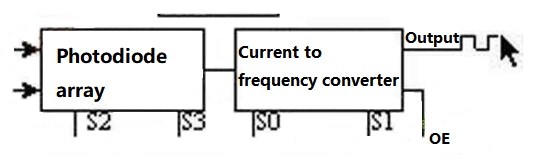
Internal structure of the TCS230 sensor
However, modern alternatives now offer superior performance and easier integration. For example, sensors like the TCS34725 provide:
I2C Interface: A direct digital interface that simplifies connection to microcontrollers, requiring fewer I/O pins compared to the frequency output of the TCS230.
Higher Precision and Sensitivity: Advanced filtering and integrated ADCs provide more accurate color measurements.
Integrated IR Blocking Filter: Minimizes the infrared component of incoming light, allowing for more accurate color measurements.
Lower Power Consumption: Modern sensors are designed for battery-powered and low-power applications.
While the TCS230 remains a valuable educational tool for understanding the fundamentals of color sensing, for new product development in 2026, it is recommended to use more modern and integrated sensors. [2]
References
[1] Stratview Research. (2021). Color Sensors Market. Retrieved from https://www.stratviewresearch.com/2115/Color-Sensors-Market.html
[2] Random Nerd Tutorials. Guide for TCS230/TCS3200 Color Sensor with Arduino. Retrieved from https://randomnerdtutorials.com/arduino-color-sensor-tcs230-tcs3200/
 UTMEL
UTMEL
We are the professional distributor of electronic components, providing a large variety of products to save you a lot of time, effort, and cost with our efficient self-customized service. careful order preparation fast delivery service
1.What is a color sensor?
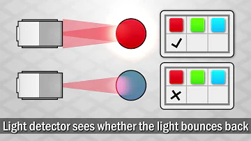
A color sensor is a type of "photoelectric sensor" which emits light from a transmitter and then detects the light reflected back from the detection object with a receiver.
2.What are color sensors used for?
It can recognize and detect colors and has many good new features in comparison with other color sensors. It is adequate for colorimeter measurement applications, such as medical diagnosis, color printing, computer color monitor calibration, and cosmetics, paint, textile, and the process control of printing materials.
3.What are the main parts of a color sensor?
Most industrial color sensors contain a white light emitter and three separate receivers. There are usually three sets of color source or color filter with peak sensitivities at wavelengths that we identify as red (580nm), green (540nm), and blue (450nm). All colors can be derived by their components.
4.What is an RGB sensor?
Colour sensors are employed to recognize/detect the color of the material in RGB (red, green, blue) scale while rejecting the unwanted infrared or ultraviolet light.
5.Where is the color sensor used?
Color sensors are generally used for two specific applications: true color recognition and color mark detection. Sensors used for true color recognition are required to "see" different colors or to distinguish between shades of a specific color. They can be used in either a sorting or matching mode.
 The Key Role of Electronic Components in IoT DevicesUTMEL01 September 20235599
The article discusses the pivotal role of electronic components in Internet of Things (IoT) devices. IoT devices work by capturing real-world data using sensors, processing it through a microcontroller, and then sending it to the cloud for further analysis.
Read More How to Identify the Perfect Proximity Sensor for Your ApplicationUTMEL19 July 20251510
Find the best proximity sensors for your project by evaluating material, sensing range, environment, and system needs to ensure optimal performance and reliability.
Read More Trusted Vibration Sensors for Homeowners and Industry ProfessionalsUTMEL17 July 20251190
Compare top vibration sensors for home and industrial use. Find trusted options for security, predictive maintenance, and equipment protection.
Read More Wiring and Mounting Photoelectric Sensors in 2025UTMEL15 July 20251411
Wire and mount photoelectric sensors in 2025 with step-by-step safety, wiring, and alignment tips for reliable installation and optimal sensor performance.
Read More Essential Tips for Picking the Best Gas SensorUTMEL15 July 20252730
Find out how to select gas sensors by matching target gases, environment, and compliance needs for reliable and accurate gas detection in any setting.
Read More
Subscribe to Utmel !
