Linear Induction Motor: Working Principle, Characteristics, and Applications

Single Phase Linear Induction Motor
Catalog
| I. General Introduction | 1. Design |
| 2. Working Principle | |
| 3. Advantages and Disadvantages | |
| II. Characteristics | |
| III. Applications | |
Charles Wheatstone began designing a linear induction motor in London in the 1840s, but it continues to be inefficient. Whereas Hermann Kemper developed the operating model in 1935, and Eric introduced the full-size operating version in 1940. Following that, this device was used in a variety of applications across a variety of industries. Linear Induction Motor, its operating theory, performance, architecture, construction, advantages and drawbacks, and main applications are all explained in detail in this article. Let's take a closer look at the concept.
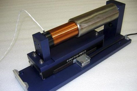
LIM stands for Linear Induction Motor, and it is an improved version of the rotary induction motor that produces linear translational motion instead of rotating motion. Other than rotating torque, this device generates linear movement and force. By cutting a radically shaped cut in the revolving induction and thus leveling the section, the design and functionality of the linear induction motor can be demonstrated in the diagram below.
The output is a leveled stator or a stator with iron-plated laminations on the upper side that carry three-phase multiple poles windings with conductors angled at 900 degrees to the motion direction. It also includes a squirrel-enclosed type of winding, which is usually made up of an endless aluminum or copper sheet held on a solid plated iron support.
Regardless of the device's name, not all linear induction motors generate linear movement, and only a few of them are used to deliver large-diameter revolutions, making the use of endless primary sections more expensive.
I. General Introduction of Linear Induction Motor
1. Design of Linear Induction Motor
And if it does not seem to be a standard induction motor, the basic structure and architecture of a linear induction motor are almost identical to those of a three-phase induction motor. The primary portion of the linear induction motor is created where a cut is made in the stator section of a polyphase induction motor and positioned on a flat surface. Similarly, when a cut is made in the rotor portion of a polyphase induction motor and positioned on a flat surface, the linear induction motor's secondary section is formed.
In addition, there is a model of linear induction motor called DLIM (Double-Sided Linear Induction Motor) that is used to increase performance. The main segment is situated on the opposite end of the secondary section in this model. On both the main and secondary sides, this design is used to increase flux utilization. This is how a linear induction motor is designed.
2. Working Principle of Linear Induction Motor
When a controlled three-phase control is used to energize the primary section of the engine, flux flow happens all over the length of the primary section. The spinning magnetic field in the stator portion of a three-phase induction motor is equivalent to this linear rotation of the magnetic field.
Because of the relative acceleration between the conductor and flux movement, there would be the induction of electric current in the secondary winding conductors. The induced current interacts with the flux movement to produce either a linear or a circular thrust of energy, as seen by:
Vs = 2tfs m/sec
If the primary section is kept steady as the second section travels, the force forces the secondary section in the same direction as the primary section, creating required rectilinear displacement. As a power supply is applied to the device, the produced field becomes a linear moving field, with the velocity represented by the equation above.
The quantity of supply frequency calculated in Hz is expressed by ‘fs' in the equation.
The linear moving field estimated in m/sec is denoted by the letter ‘Vs.'
The letter ‘t' stands for the pitch of a linear pole, which is the distance between poles measured in meters.
V = (1-s)Vs
According to the same logic, in the case of an induction motor, the secondary runner does not retain the same speed as the magnetic field's speed value. As a result of this, a slip happens.
The below is a schematic of a linear induction motor:

3. Advantages and Disadvantages of Linear Induction Motor
Advantages
At the time of assembly, there are no magnetic attractional forces. Since LIM systems do not have permanent magnets, there is no attractional force when the machine is assembled.
Linear induction motors also have the bonus of being able to fly long distances. Permanent magnets do not have secondary parts, so these systems are mostly used for long-length applications. The lack of magnets in the second segment enables these devices to be inexpensive since the creation of a magnetic track is vital to the device's price.
Suitable for heavy-duty applications. Linear induction motors are most widely used in high-pressure linear motor applications, where steady force ratings of nearly 25gms of acceleration and hundreds of pounds are required.
Disadvantages
LIM systems are more complex to develop because they require sophisticated control algorithms.
At the time of service, these have strengthened attractional forces.
When at a standstill, displays little force.
The increased physical scale of the device necessitates a greater package size.
For accessibility, more power is needed. The efficiency of permanent magnet linear motors is lower, and they produce more heat. This necessitates the integration of water cooling equipment into the architecture.
II. Characteristics of Linear Induction Motor
End Effect
In comparison to circular induction motors, LIM has a function known as the "End Effect." The end result is quality and output losses, which are caused by magnetic energy being taken away and lowered at the main section's end due to relative motion between the primary and secondary sections.
Only in the secondary segment does the system tend to have the same versatility as a rotary machine, demanding that it be approximately two poles apart but with a minimal main decrease in the thrust that exists at low slip, despite the fact that it is either 8 or more poles longer. Owing to the nature of end effects, LIM machines are unable to work light, while general-purpose induction motors have the ability to perform a motor with a closer synchronous field in low-load conditions. In comparison, linear motors produce equivalent losses as a result of the end effect.
Thrust
The LIM devices generate a drive that is virtually identical to that of general induction motors. Even if modulated by end results, these drive forces have a characteristic curve that is very similar to slide. A Tractive effort is another term for this. It is shown by:
F = Pg/Vs
measured in Newtons
Levitation
Furthermore, unlike rotary engines, LIM machines have an electrodynamic levitation force that has zero reading at ‘0' slip, resulting in an essentially defined amount of distance as the slip rises in any direction. This happens only in single-sided engines, as it does not normally occur where the secondary segment is protected by an iron supporting plate since this provides an attraction that overcomes the lifting strain.
Transverse Edge Effect
Linear Induction Motors often have a Transverse edge effect, which means that current paths in the same direction of travel develop losses, minimizing the effective thrust. As a consequence, the transverse edge effect arises.
Performance
The efficiency of a linear induction motor can be calculated using the principle described below, in which the moving wave's synchronous speed is expressed by:
Vs = 2f (pith of the linear pole)……..m/s
‘f’ corresponds to supplied frequency measured in Hertz
The speed of the secondary portion of a rotary induction motor in the LIM is less than the synchronous speed and is given by:
Vr = Vs (1-s), 's' is the LIM slip and it is
S = (Vs – Vr)/Vs
The linear force is given by F = power of the air gap/Vs
The thrust velocity curve of the LIM is almost equivalent to the rotary induction motor's speed vs torque curve. By compared the linear induction motor to the rotary induction motor, the linear induction motor needs a greater air gap, which results in increased magnetizing current and minimal output and power factor.
In RIM, the stator and rotor parts have identical regions, while in LIM, one segment is shorter than the other. The shorter section would have more uninterrupted passage than the longer section at a constant speed.
III. Applications of Linear Induction Motor
In systems such as these, linear induction motors are used primarily.
Conveyor belts with aluminum
Controlling machinery that is electronic
High-velocity circuit breaker actuators
Applications for improving shuttles
How does a linear induction motor work?
The Linear Induction Motor is similar in construction to a circular motor that has been opened out flat. The magnetic field now sweeps across the flat motor face instead of rotating. The stator generally consists of a multi phase winding in a laminated iron core.
What is linear motor technology?
A linear motor is an electric motor that has had its stator and rotor "unrolled" thus instead of producing a torque (rotation) it produces a linear force along its length. ... High-acceleration linear motors are typically used in studies of hypervelocity collisions, as weapons, or as mass drivers for spacecraft propulsion.
Do linear induction motors use magnets?
A linear induction motor (LIM) is an alternating current (AC), asynchronous linear motor that works by the same general principles as other induction motors but is typically designed to directly produce motion in a straight line. Their practical uses include magnetic levitation, linear propulsion, and linear actuators.
 What is a Servo Drive?UTMEL16 June 20213889
Servo drive, also known as "servo controller" and "servo amplifier", is a kind of controller used to control servo motors. Its function is similar to that of frequency converters acting on ordinary AC motors, and it is part of the servo system. The servo drive is mainly used in high-precision positioning systems. Generally, the servo motor is controlled by three methods of position, speed, and torque to achieve high-precision transmission system positioning.
Read More What is a Switched Reluctance Motor?UTMEL09 July 20246740
Switched reluctance motor is a type of speed-regulating motor developed after DC motor and brushless DC motor. Product power levels range from several watts to hundreds of kilowatts, and are widely used in household appliances, aviation, aerospace, electronics, machinery, and electric vehicles.
Read More Types, Working, and Selection of DC MotorUTMEL27 March 202515479
A direct current motor (DC motor) is an electric motor that operates on direct current. The operation of an electric motor is based on basic electromagnetism. When a current-carrying conductor is put in an external magnetic field, it will feel a force that is equal to the current in the conductor and the frequency of the external magnetic field.
Read More Linear Induction Motor: Working Principle, Characteristics, and ApplicationsUTMEL02 March 202113049
LIM stands for Linear Induction Motor, and it is an improved version of the rotary induction motor that produces linear translational motion instead of rotating motion. Other than rotating torque, this device generates linear movement and force. By cutting a radically shaped cut in the revolving induction and thus leveling the section, the design and functionality of the linear induction motor can be demonstrated in the diagram below.
Read More Stepper Motor: Types, Working and ApplicationsUTMEL26 December 20258575
A brushless, synchronous electric motor that converts digital pulses to mechanical shaft rotation is known as a stepper motor. When operated by a sequentially switched DC power supply, the normal shaft motion is made up of discrete angular motions of approximately uniform magnitude.
Read More
Subscribe to Utmel !
![E214F00CS]() E214F00CS
E214F00CSLantronix
![E214F002S]() E214F002S
E214F002SLantronix
![E228HPL3S]() E228HPL3S
E228HPL3SLantronix
![ICR-3241W]() ICR-3241W
ICR-3241WAdvantech
![E214G001S]() E214G001S
E214G001SLantronix
![E218F005S]() E218F005S
E218F005SLantronix
![QSH6018-65-28-210-10k]() QSH6018-65-28-210-10k
QSH6018-65-28-210-10kTRINAMIC Motion Control GmbH
![QBL4208-100-04-025-1k]() QBL4208-100-04-025-1k
QBL4208-100-04-025-1kTRINAMIC Motion Control GmbH
![OAM82AN-11-1WB]() OAM82AN-11-1WB
OAM82AN-11-1WBOrion Fans
![AFR14A901B]() AFR14A901B
AFR14A901BALPS ALPINE CO., LTD


