Product
 Brand
Brand Articles
 Tools
Tools
RTD Sensors: Working Principle, Features and Applications
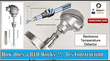
How does a RTD Works?
Introduction: What is an RTD sensor?
RTD (Resistance Temperature Detector) sensors, i.e. Resistance Temperature Detectors, are high-precision sensors that utilize the property of metal resistance value changing with temperature to measure the temperature.RTD sensors are usually composed of thin wires of pure metals such as platinum, nickel, or copper, which are wrapped around a ceramic or glass core to form a precision resistance element. When the temperature changes, the resistance value of the RTD sensor will change accordingly, and by measuring the change in this resistance value, we can accurately calculate the ambient temperature.
Compared with other temperature sensors such as thermocouples, RTD sensors are widely used in industrial automation, process control, medical equipment and precision instruments for their high accuracy, good stability and excellent repeatability.
I. Working principle of RTD sensor
1. Basic principles of operation
The operating principle of RTD sensors is based on the property that the resistance value of a metal conductor changes with temperature. When the temperature increases, the vibrations of the metal atoms intensify, impeding the flow of electrons and increasing the resistance; conversely, when the temperature decreases, the vibrations of the metal atoms weaken and the resistance value decreases. For most RTD sensors, the resistance value shows a good linear relationship with temperature, especially in a given temperature range.
The temperature-resistance relationship of an RTD sensor can be expressed by the following equation:
R(t) = R₀[1 + α(t - t₀)]
Where: - R(t): resistance value at temperature t - R₀: resistance value at reference temperature t₀ (usually 0°C) - α: resistance temperature coefficient
The temperature coefficient α can be calculated by the following equation:
α = (R₁₀₀ - R₀) / (100°C × R₀)
where R₀ and R₁₀₀ are the resistance values of the sensor at 0°C and 100°C, respectively.
2. Sensor structures
RTD sensors can be categorized into three main types based on their construction:
a) Wire-wound RTDs
Wire-wound RTDs are the most traditional design, consisting of a metal wire (usually platinum) wound around a ceramic or glass substrate. This construction provides good stability and a wide temperature measurement range, but is bulky.

Wire-wound RTD structure
b) Thin Film RTD
Thin-film type RTDs are manufactured by depositing a thin metal film (usually platinum) on a ceramic substrate. Smaller in size, faster in response, and lower in cost than wire-wound types, thin-film RTDs are the most commonly used type of RTD today.

Membrane type RTD structure
c) Coiled element type RTD
These RTDs coil wire around a special insulating material to provide better protection against vibration and mechanical shock for use in harsh environments.

Coiled element type RTD structure
3. Protection design
To protect the sensitive resistive element, RTD sensors are often designed with a protective sleeve. The protective sleeve is made of a chemically resistant metal alloy that protects the sensitive internal components in harsh environments. For applications below 250°C, PVC or silicone rubber is often used as an insulating material; at higher temperatures, special high-temperature insulating materials are used.
Second, RTD sensor characteristics
1. Tolerance levels
RTD sensors are designed according to the "DIN" standard curve which defines the characteristics of platinum resistance temperature sensors. According to the DIN standard, a 100 ohm platinum RTD has a base resistance of 100 ohms at 0°C and a temperature coefficient of 0.00385 ohms/ohm/°C. The RTDs are designed for use in a wide range of applications.
The DIN standard defines three tolerance classes:
DIN Class A: ±(0.15 + 0.002 |T|°C)
DIN Class B: ±(0.3 + 0.005 |T|°C)
DIN Class C: ±(1.2 + 0.005 |T|°C)
where |T| denotes the absolute value of the temperature. class A sensors provide the highest accuracy and are typically used in precision measurement situations; class B is the industry standard; and class C is used in general application scenarios.
The following are nominal output values for DIN standard RTDs at different temperatures:
2. Component types
When selecting an RTD sensor, the first thing to consider is the measuring instrument that goes with it. The most commonly used RTD element is a 100 ohm platinum resistor with a temperature coefficient of 0.00385.
3. Sensor connectivity
RTD sensors can be connected in a variety of ways, the most common being a three-wire connection. The diagrams of the different connection methods are shown below:

RTD sensor connection
a) Two-wire connection
A two-wire connection is often used where accuracy is not required. This type of connection is the simplest, but there are measurement errors caused by the resistance of the wire, because the wire resistance is in series with the sensor resistance and cannot be distinguished.
b) Three-wire connection
The three-wire connection adds a compensation lead to eliminate the effect of the wire resistance by measuring it twice. The measuring unit first measures the total resistance of the sensor and the connecting wire, then measures the resistance of the compensating wire, which is subtracted to obtain the net resistance of the sensor. Three-wire sensors offer a good balance of accuracy and convenience and are the most commonly used connection for industrial applications.
c) 4-wire connection
Four-wire connections provide the highest accuracy measurements, completely eliminating the effects of wire resistance. However, many industrial controllers and measuring instruments cannot support true four-wire measurements.
4. Conductor effects
When measuring RTD resistance, an unbalanced Wheatstone bridge is usually used. To obtain accurate readings, the effects of external factors must be minimized or compensated for.

Schematic diagram of RTD wire effect
In a two-wire connection, the lead wire resistance is in series with the sensor resistance and directly affects the measurement results. When the sensor resistance is high and the wire resistance is low, a two-wire RTD can be used; however, when the wire resistance is high, compensation must be made.
A three-wire connection allows for compensation. As shown in the figure, the power supply is connected to one side of the RTD through L3, which allows L1 and L2 to be located in opposite arms of the bridge, balancing each other and having little effect on the bridge output voltage.
A three-wire connection is recommended for RTDs with low base resistance, especially when wire resistance may significantly affect reading accuracy.
III. Comparison of RTD sensors and thermocouples
RTD sensors and thermocouples are two of the most commonly used temperature measurement devices, and they each have their advantages and disadvantages. Understanding their differences can help in choosing the best temperature sensor for a particular application.
RTD sensors offer greater accuracy and stability in low to medium temperature ranges, while thermocouples are suitable for a wider range of temperatures, especially in high temperature environments. For precision temperature control applications, RTDs are preferred; while in harsh environments or extreme temperature conditions, thermocouples may be more appropriate.
Fourth, RTD sensor application scenarios
1. Industrial automation
In industrial automation, RTD sensors are widely used for: - Process temperature monitoring and control - Heat exchanger performance monitoring - Reactor temperature control - Pipe temperature measurement - Tank temperature monitoring
2. Automotive industry
In the automotive industry, RTD sensors are used for: - Engine temperature monitoring - Oil level sensors - Intake air temperature sensors - Exhaust system temperature monitoring - Battery management system temperature monitoring
3. Food processing and pharmaceuticals
In the food and pharmaceutical industries, RTD sensors are used for: - Temperature control of sterilization processes - Temperature monitoring of storage facilities - Temperature logging of cold chain transportation - Temperature control of fermentation processes - Quality assurance testing
4. Electronics and computers
In the electronics and computer industry, RTD sensors are used for: - Amplifier over-temperature monitoring - Power supply temperature monitoring - Server room temperature control - Electronic component temperature testing - Thermal system performance evaluation
5. Medical equipment
In the medical field, RTD sensors are used for: - Medical device temperature control - Refrigerated drug storage monitoring - Blood temperature monitoring - Laboratory equipment temperature control - Sterilization equipment temperature verification
6. Aerospace
In the aerospace industry, RTD sensors are used for: - Engine temperature monitoring - Hydraulic system temperature control - Fuel temperature monitoring - Environmental control systems - Electronics cooling system monitoring
V. RTD Sensor Selection Guide
1. Key considerations
The following key factors should be considered when selecting an RTD sensor.
a) Temperature range
Determine the temperature measurement range required for your application and select an RTD sensor that will cover that range. Platinum RTDs typically cover -200°C to 600°C and nickel RTDs are suitable for temperatures below 300°C.
b) Precision requirements
Select the appropriate tolerance class based on the application's accuracy requirements. class A provides the highest accuracy, but also costs more.
c) Response time
If the application requires a fast response to temperature changes, a thin-film RTD or a smaller design should be selected.
d) Connection method
Connections are selected based on accuracy requirements and system complexity. For general industrial applications, three-wire connections provide a good balance of accuracy and simplicity.
(e) Environmental factors
Consider the vibration, chemical corrosion, humidity and other factors of the application environment to select the appropriate protective casing and sealing design.
f) Compatibility
Ensure that the RTD sensor selected is compatible with existing instrumentation and control systems, especially the temperature coefficient and base resistance values.
2. Common Selection Errors
Avoid the following common selection errors: - Ignoring the self-heating effect: when the measurement current is too large, it will cause the sensor itself to heat up, affecting the measurement accuracy - Neglecting the environmental impact: did not take into account the environmental factors such as vibration, electromagnetic interference - Wire length issues: for long distance applications, did not choose the appropriate connection to compensate for the resistance of the wire - Overspecification: selecting a high-precision sensor that exceeds the actual needs and increases unnecessary costs - Temperature range mismatch: The temperature range of the selected sensor does not cover the application requirements.
VI. RTD Sensor Maintenance and Troubleshooting
1. Maintenance guidelines
To ensure the long-term accuracy and reliability of the RTD sensor, the following maintenance measures should be taken.
Periodic calibration: Sensors are calibrated periodically according to manufacturer's recommendations or industry standards
Keep it clean: avoid accumulation of dirt or chemicals on the sensor surface
Check connections: Periodically check that the terminals and wires are securely connected.
Protective measures: in harsh environments to ensure that the protective casing is intact
Logging performance: track changes in sensor readings over time for early detection of potential problems
2. Common faults and solutions
VII. RTD Sensors Market Trends and Development Prospects
1. Market size and growth
According to the latest market research data, the Global RTD Temperature Sensors Market is showing a robust growth trend: - Global RTD Sensors Market size is estimated to be around USD 1 billion in 2024 - Expected to grow to USD 1,652 million by 2031 - Compound Annual Growth Rate (CAGR) of around 3.5% during 2025-2031
China RTD Sensors Market reached RMB 1,095 million by 2024 and is a significant part of the global market.
2. Trends in technological innovation
RTD sensor technology is undergoing multiple innovations.
Thin-film technology breakthrough: New thin-film manufacturing process reduces cost and size
Advances in Materials Science: Developing New Metal Alloys to Improve Performance and Temperature Range
Digital integration: RTD sensors integrated with digital interfaces for intelligence
Wireless Transmission: Development of RTD Sensor Systems with Wireless Communication Functions
Self-diagnostics: Intelligent RTD sensors with integrated self-test and troubleshooting capabilities
3. Application extensions
RTD sensor applications are expanding into several emerging areas.
Industrial Internet of Things (IIoT): as the core of a smart factory temperature monitoring network
Wearables: Miniaturized RTDs for Health Monitoring Devices
New Energy: Battery Management System Temperature Monitoring
Intelligent Buildings: Integration into Building Automation Systems
Precision agriculture: soil and crop temperature monitoring
4. Market competition patterns
The RTD sensors market is highly competitive with the presence of numerous domestic and foreign manufacturers. The market is moderately concentrated but is gradually moving towards fragmentation. Key market players are consolidating their market position through product innovation, mergers and acquisitions, and expansion of distribution channels.
VIII. Conclusion
RTD sensors play a key role in a wide variety of temperature measurement applications due to their high accuracy, good stability and excellent repeatability. From industrial automation to medical devices, from the automotive industry to food processing, RTD sensors are used in virtually every application where precise temperature measurement is required.
As technology continues to advance, RTD sensors are moving towards being smaller, smarter and more integrated, and will play an even more important role in the future era of the Internet of Things and smart manufacturing. Understanding how RTD sensors work, their characteristics, selection guidelines, and maintenance methods is critical for engineers and technicians to help them choose the most appropriate temperature measurement solution for a particular application.
Choosing the right RTD sensor not only improves the measurement accuracy and reliability of the system, but also optimizes cost-effectiveness and ensures the long-term stable operation of the temperature monitoring system.
 UTMEL
UTMEL
We are the professional distributor of electronic components, providing a large variety of products to save you a lot of time, effort, and cost with our efficient self-customized service. careful order preparation fast delivery service
How does a RTD sensor work?
RTDs work on a basic correlation between metals and temperature. As the temperature of a metal increases, the metal's resistance to the flow of electricity increases. Similarly, as the temperature of the RTD resistance element increases, the electrical resistance, measured in ohms (Ω), increases.
What is difference between RTD and thermocouple?
Most RTDs are limited to a maximum temperature of 1000 degrees Fahrenheit. ... In contrast, certain thermocouples can be used to measure up to 2700 degrees Fahrenheit. RTDs are superior to thermocouples in that their readings are more accurate and more repeatable.
How is RTD used to measure temperature?
There are essentially three different methods to measure temperature using RTDs. Connect the red RTD lead to the excitation positive. Place a jumper from the excitation positive pin to the channel positive on the data acquisition device. Connect the black (or white) RTD lead to the excitation negative.
Why does RTD have 3 wires?
To compensate for lead wire resistance, 3 wire RTDs have a third wire that provides a measurement of the resistance of the lead wire and subtracts this resistance from the read value. This correction compensates for the effect of the resistance of the long lead wires on the temperature measurement and results in improved accuracy. Because 3 wire RTDs are so effective and affordable, they have become the industry standard. They are used in a variety of industrial applications and processes, especially in refineries and chemical and petrochemical plants where temperature monitoring and control is of extreme importance. The 3 wire RTDs provide good accuracy and repeatability at reasonable cost and have been adopted by all major temperature transmitter manufacturers as the standard type of sensor for most applications.
What is difference between PT100 and RTD?
There is no difference a PT100 is a version of a RTD (resistance temperature detector). What is an RTD? A resistance temperature detector, also known as an RTD or resistance thermometer, is a type of temperature sensor.
 The Key Role of Electronic Components in IoT DevicesUTMEL01 September 20235892
The article discusses the pivotal role of electronic components in Internet of Things (IoT) devices. IoT devices work by capturing real-world data using sensors, processing it through a microcontroller, and then sending it to the cloud for further analysis.
Read More Accelerometer Sensors Guide: Working Principle, Circuit Design, Specifications, and ApplicationsUTMEL25 June 2026407
A practical accelerometer sensor guide covering working principles, MEMS and piezoelectric types, datasheet specifications, circuit design, mounting, applications, and selection.
Read More 2026 ADAS Sensors: Supply Outlook and Alternative SourcingUTMEL18 July 2026417
Automotive cleanroom assembly integrating advanced driver assistance systems. The automotive industry faces a structural semiconductor deficit in 2026, driven not by pandemic-era demand shocks but by AI data centers absorbing global foundry capacity on legacy nodes (40nm-90nm) where 95% of automotive-grade components are manufactured. Video demonstrations of these systems show a "machine view" overlay with red crosshairs tracking pedestrian movement and sudden cut-ins before traditional collision thresholds are triggered.
Read More How to Identify the Perfect Proximity Sensor for Your ApplicationUTMEL19 July 20251776
Find the best proximity sensors for your project by evaluating material, sensing range, environment, and system needs to ensure optimal performance and reliability.
Read More Trusted Vibration Sensors for Homeowners and Industry ProfessionalsUTMEL17 July 20251423
Compare top vibration sensors for home and industrial use. Find trusted options for security, predictive maintenance, and equipment protection.
Read More
Subscribe to Utmel !
![EBM6BV010H]() EBM6BV010H
EBM6BV010HMenda
![ETM80WV300]() ETM80WV300
ETM80WV300Menda
![EPM80CP200]() EPM80CP200
EPM80CP200Menda
![T39-K]() T39-K
T39-KHakko
![35395]() 35395
35395Menda
![35724]() 35724
35724Menda
![35074]() 35074
35074Menda
![35265]() 35265
35265Menda
![35800]() 35800
35800Menda
![0022/]() 0022/
0022/Molex