Product
 Brand
Brand Articles
 Tools
Tools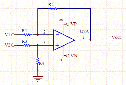

Op-Amp Voltage and Gain Calculator Overview
The Op-Amp Voltage and Gain Calculator helps estimate the output voltage, inverting gain, and non-inverting gain of a basic operational amplifier circuit. By entering the resistor values, input voltages, and supply rail voltages, you can quickly check how an op-amp stage will amplify or invert a signal.
This calculator is useful when designing signal conditioning circuits, sensor interfaces, active filters, audio preamplifiers, comparator front-end circuits, and other analog circuits that use negative feedback around an operational amplifier.
The tool accepts resistor values R1, R2, R3, and R4, input voltages V1 and V2, and the positive and negative supply rails Vp and Vn. It then calculates the expected output voltage and indicates whether the output is clipped by the supply voltage limits.
What Is an Operational Amplifier?
An operational amplifier, or op-amp, is a high-gain differential voltage amplifier. It has a non-inverting input marked with a plus sign, an inverting input marked with a minus sign, and one output. In most linear amplifier circuits, feedback resistors are used to set a controlled closed-loop gain.
In an ideal op-amp model, the input terminals draw no current and the feedback loop drives the two input terminals to nearly the same voltage. These assumptions make it possible to calculate many op-amp circuits using simple resistor ratios.
What This Calculator Can Calculate
Estimated output voltage for the entered input voltages and resistor network.
Inverting gain, which shows how much the inverting input signal is amplified and phase-inverted.
Non-inverting gain, which shows how much the non-inverting input signal is amplified without phase inversion.
Output clipping when the calculated voltage exceeds the positive or negative supply rail.
For a differential amplifier or a more complex circuit, resistor matching and input common-mode range become especially important. Use this calculator as a first-pass design aid, then verify the result against the selected op-amp datasheet and circuit requirements.
Input Parameters Explained
| Input | Meaning | Typical Unit |
|---|---|---|
| R1 | Input or reference resistor used in the feedback network, depending on the circuit topology. | kOhm |
| R2 | Feedback resistor or gain-setting resistor paired with R1. | kOhm |
| R3 | Additional input or divider resistor used by the op-amp calculator circuit. | kOhm |
| R4 | Additional feedback, divider, or matching resistor used with R3. | kOhm |
| V1 | Input voltage applied to one side of the op-amp circuit. | V |
| V2 | Input voltage or reference voltage applied to the other side of the op-amp circuit. | V |
| Vp | Positive supply rail of the op-amp. | V |
| Vn | Negative supply rail of the op-amp. For a single-supply circuit, this is often 0 V. | V |
Basic Op-Amp Gain Formula
The general voltage gain relationship is:
Vout = A * Vin
Where:
Vout = output voltage
Vin = input voltage
A = closed-loop voltage gain
In practical feedback amplifiers, the closed-loop gain is usually set by resistor ratios, not by the extremely high open-loop gain of the op-amp itself.
Inverting Op-Amp Formula
For a standard inverting amplifier, the input signal is applied to the inverting input through an input resistor, and the feedback resistor connects the output back to the inverting input.
A = -R2 / R1
Vout = -(R2 / R1) * Vin
The negative sign means the output signal is inverted, or 180 degrees out of phase with the input signal. If R1 and R2 are equal, the circuit has a gain of -1 and works as an inverting buffer.
Non-Inverting Op-Amp Formula
For a standard non-inverting amplifier, the input signal is applied to the non-inverting input, while the feedback divider sets the gain.
A = 1 + R2 / R1
Vout = (1 + R2 / R1) * Vin
The output signal stays in phase with the input signal. A non-inverting amplifier has a minimum gain of 1. When the output is directly connected to the inverting input, the circuit becomes a voltage follower or buffer.
Output Voltage With Two Inputs
Many op-amp calculator circuits include two input voltages and four resistors. In a common single-op-amp topology, the output can be estimated by combining the inverting contribution from one input and the non-inverting contribution from the other input:
Vout = V2 * (R4 / (R3 + R4)) * (1 + R2 / R1) - V1 * (R2 / R1)
If the resistor ratios are matched, the circuit can behave like a difference amplifier, where the output is proportional to the voltage difference between two inputs:
Vout = Gain * (V2 - V1)
The exact formula depends on the resistor labels and circuit diagram used by the calculator. Always match the formula to the schematic before using the result in a final design.
Example Calculation
For a simple inverting amplifier:
R1 = 10 kOhm
R2 = 100 kOhm
Vin = 0.2 V
The gain is:
A = -100 kOhm / 10 kOhm = -10
The output voltage is:
Vout = -10 * 0.2 V = -2 V
For a simple non-inverting amplifier using the same resistor ratio:
A = 1 + 100 kOhm / 10 kOhm = 11
If Vin = 0.2 V, the output is:
Vout = 11 * 0.2 V = 2.2 V
Why Output Clipping Happens
An ideal formula may calculate an output voltage beyond the op-amp's supply rails, but a real op-amp cannot output a voltage higher than its positive rail or lower than its negative rail. When the calculated output exceeds the available output range, the signal is clipped.
For example, if an op-amp is powered from 0 V and 5 V, a calculated output of 7 V cannot be produced. The actual output will saturate near the upper supply limit. Many real op-amps also cannot swing exactly to the rails unless they are rail-to-rail output devices.
How to Use This Calculator
Choose the op-amp circuit type, such as inverting, non-inverting, or a two-input configuration.
Enter resistor values in kOhm according to the calculator diagram.
Enter the input voltages V1 and V2.
Enter the positive and negative supply rails as Vp and Vn.
Calculate the output voltage and gain values.
Check whether the output is clipped by the supply rails.
Compare the result with the selected op-amp's input and output voltage range in the datasheet.
How to Interpret the Result
| Result | Meaning | What to Check |
|---|---|---|
| Positive gain | The output is in phase with the input signal. | Usually associated with non-inverting operation. |
| Negative gain | The output is inverted relative to the input signal. | Usually associated with inverting operation. |
| Output is within Vp and Vn | The calculated output is inside the supply limits. | Still verify real output swing limits in the datasheet. |
| Output is clipped | The calculated output exceeds the supply range. | Reduce gain, lower the input signal, or use a wider supply voltage if the op-amp allows it. |
Practical Design Notes
Use resistor values that keep input bias current errors acceptable for the selected op-amp.
Check the op-amp gain-bandwidth product if the signal frequency is high.
Make sure the input common-mode voltage range includes the expected input voltages.
Check output swing limits, especially in single-supply circuits.
Use precision resistors when gain accuracy or common-mode rejection matters.
Add supply decoupling capacitors close to the op-amp power pins in real hardware.
Confirm stability when driving capacitive loads or using high feedback resistance.
Common Mistakes to Avoid
Forgetting that inverting gain is negative.
Assuming the output can swing exactly to the supply rails.
Using resistor ratios correctly but ignoring the op-amp's input common-mode range.
Choosing very high resistor values and creating large offset errors from input bias current.
Using a high gain without checking bandwidth and slew rate.
Mixing up R1, R2, R3, and R4 compared with the circuit diagram.
Using ideal formulas for a precision design without checking real op-amp datasheet limits.
When This Calculator Is Not Enough
This calculator is best for quick voltage and gain estimates. More detailed analysis is needed when the circuit has high frequency signals, large output current, capacitive loads, very small input signals, high source impedance, strict noise requirements, precision DC accuracy requirements, or a single-supply input range close to ground or the positive rail.
In those cases, check the op-amp datasheet for offset voltage, input bias current, input common-mode range, output swing, slew rate, gain-bandwidth product, noise, and load-drive capability. Simulation and bench testing are recommended before final production.
Frequently Asked Questions
What is op-amp gain?
Op-amp gain is the ratio between output voltage and input voltage. In closed-loop amplifier circuits, the gain is usually controlled by external feedback resistors.
Why is the inverting gain negative?
The negative sign shows that the output voltage moves in the opposite direction from the input voltage. This means the signal is phase-inverted by 180 degrees.
Why does the non-inverting gain include 1?
In a non-inverting amplifier, the output includes the input voltage plus the voltage developed across the feedback network. This creates the gain formula 1 + R2/R1.
What does output clipping mean?
Output clipping means the calculated output voltage is beyond what the op-amp can produce from its supply rails. The real output saturates near the rail instead of following the ideal formula.
Can I use this calculator for single-supply op-amp circuits?
Yes. Enter the positive supply as Vp and enter 0 V as Vn if the circuit is powered from a single supply. Also check whether the chosen op-amp supports the required input and output voltage range.
Can this calculator replace an op-amp datasheet?
No. The calculator gives ideal or simplified results. Real op-amps have limitations such as offset voltage, input bias current, output swing, bandwidth, slew rate, noise, and load-drive capability.