Product
 Brand
Brand Articles
 Tools
Tools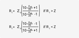

Reflection Attenuator Calculator Overview
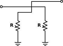
The Reflection Attenuator Calculator helps calculate the two possible resistor values for a reflection attenuator. Unlike a standard T-pad or pi-pad attenuator, a reflection attenuator uses controlled reflection from matched termination elements to reduce signal level.
Enter the desired attenuation in decibels and the system impedance Z0. The calculator returns two possible values for R1: one value greater than Z0 and one value smaller than Z0. Both solutions can produce the same attenuation magnitude when used in the correct reflection attenuator structure.
What Is a Reflection Attenuator?
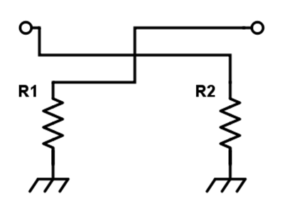
A reflection attenuator is an attenuator topology that uses a coupler, hybrid, or similar RF network together with reflective terminations. The attenuation is controlled by the reflection coefficient of the termination resistors. This is different from a purely absorptive attenuator, where resistors dissipate the signal in a direct pad network.
Reflection attenuators are often used in variable attenuator or phase-control circuits because the termination resistance can be switched, varied, or electronically controlled. The practical circuit must be designed so that reflected power is routed correctly by the coupler or hybrid instead of returning to the source in an uncontrolled way.
Reflection Attenuator Formulas
For a desired attenuation entered as a positive dB value:
K = 10^(AdB / 20)
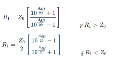
The resistor solution greater than Z0 is:
R1 high = Z0 × (K + 1) / (K - 1)
The resistor solution smaller than Z0 is:
R1 low = Z0 × (K - 1) / (K + 1)
| Symbol | Meaning | Typical Unit |
|---|---|---|
| R1 high | Termination resistor solution greater than the system impedance. | Ω |
| R1 low | Termination resistor solution smaller than the system impedance. | Ω |
| Z0 | Characteristic impedance of the RF system. | Ω |
| AdB | Required attenuation, entered as a positive loss value. | dB |
| K | Voltage loss ratio used to calculate the reflection termination. | unitless |
Why There Are Two R1 Values
The reflection coefficient of a purely resistive termination depends on how far the resistor is from the system impedance. A resistor above Z0 and a resistor below Z0 can have the same reflection magnitude but opposite reflection sign. That is why the calculator gives two possible resistor values.
When the two values are normalized to Z0, they are reciprocal solutions. For example, in a 50 Ω system, one solution may be much larger than 50 Ω while the other is much smaller than 50 Ω.
Example Calculation
Suppose the desired attenuation is 10 dB in a 50 Ω system.
K = 10^(10 / 20) ≈ 3.162
R1 high = 50 × (3.162 + 1) / (3.162 - 1) ≈ 96.3 Ω
R1 low = 50 × (3.162 - 1) / (3.162 + 1) ≈ 26.0 Ω
Either resistor value can represent the same reflection magnitude in the proper circuit. The correct choice depends on the attenuator architecture, switching device, biasing method, power handling, and the desired phase behavior.
Common Values for a 50 Ω System
| Attenuation | R1 High | R1 Low |
|---|---|---|
| 3 dB | 292.4 Ω | 8.55 Ω |
| 6 dB | 150.5 Ω | 16.6 Ω |
| 10 dB | 96.3 Ω | 26.0 Ω |
| 20 dB | 61.1 Ω | 40.9 Ω |
| 30 dB | 53.3 Ω | 46.9 Ω |
These values assume ideal resistive terminations and a matched 50 Ω environment. At high attenuation, both solutions move closer to 50 Ω because the reflected signal becomes smaller.
How to Use the Calculator
Enter the target attenuation as a positive dB value. Then enter the characteristic impedance of the system. The calculator returns both resistor solutions. Use the solution that matches the intended circuit topology, switching arrangement, and phase requirement.
After selecting a resistor value, verify the complete attenuator with the coupler, hybrid, switching element, PCB layout, and load conditions included. The resistor alone does not define the complete reflection attenuator performance.
Applications
| Application | Why Reflection Attenuation Is Useful |
|---|---|
| RF variable attenuators | Allows attenuation to be changed by varying or switching reflective terminations. |
| Phase shifters | Reflection-based networks can be used in variable phase-control designs. |
| Receiver front ends | Can reduce signal level before sensitive mixer, amplifier, or detector stages. |
| Test fixtures | Provides controlled signal reduction when integrated with a suitable RF coupler or hybrid. |
| Switched attenuation banks | Discrete resistor states can create selectable attenuation steps. |
Reflection Attenuator vs Resistive Pad
| Type | Main Idea | Typical Design Concern |
|---|---|---|
| Reflection attenuator | Uses reflected signal energy from controlled terminations. | Requires the coupler or hybrid behavior to be included in the design. |
| T-pad or pi-pad | Uses a direct resistor network to absorb signal power. | Requires correct resistor values, power rating, and impedance match. |
| Bridged-T attenuator | Uses a bridge and shunt resistor network to set attenuation. | Useful when attenuation is adjusted by two main resistor values. |
Design Notes
Reflection attenuators are sensitive to the quality of the RF coupler, hybrid balance, resistor accuracy, switching device parasitics, and PCB layout. A resistor value that is mathematically correct can still produce poor performance if the hybrid has limited bandwidth or if the termination is not a clean real impedance at the operating frequency.
For practical RF work, verify insertion loss, attenuation range, phase variation, input match, output match, bandwidth, and power handling. If the circuit uses PIN diodes, FETs, or other active switching elements, also check bias isolation and nonlinear distortion.
Common Mistakes to Avoid
| Mistake | Why It Matters |
|---|---|
| Using a reflection attenuator formula for a T-pad or pi-pad | The topologies are different and require different resistor equations. |
| Ignoring the two possible R1 solutions | The high and low values can have the same reflection magnitude but different implementation behavior. |
| Using dB directly as a linear value | Convert attenuation to K with K = 10^(AdB / 20). |
| Assuming the resistor is purely resistive at RF | Package parasitics and layout can make the termination complex at high frequency. |
| Ignoring power dissipation | Reflected and absorbed power can heat the termination resistors and switching devices. |
FAQ
Why does the calculator return two resistor values?
A resistor above the system impedance and a resistor below the system impedance can produce the same reflection magnitude. The two values correspond to the two possible real terminations for the same attenuation level.
Can I use this as a normal inline attenuator?
Not by itself. A reflection attenuator normally works with a coupler or hybrid network that routes reflected power correctly. For a simple inline attenuator, use a T-pad, pi-pad, or bridged-T calculator.
What does Z0 mean?
Z0 is the characteristic impedance of the RF system, such as 50 Ω or 75 Ω. The resistor values are calculated relative to this impedance.
Which solution should I choose, the high value or the low value?
Choose the value required by your circuit architecture. The high and low values may differ in power dissipation, switching practicality, phase behavior, and device parasitic sensitivity.
Related Online Calculation Tools
Tee Attenuator Calculator - calculates resistor values for a matched T-pad attenuator.
Pi Attenuator Calculator - calculates resistor values for a matched pi-pad attenuator.
Bridged-Tee Attenuator Calculator - calculates resistor values for a bridged-T attenuator.
dBm to Watts Calculator - converts RF power between dBm and watts.