
 Product
 Brand
Brand Articles
 Tools
Tools
Basic Introduction to RF Connector

RF Connectors and what they're for
Catalog
Ⅰ Introduction
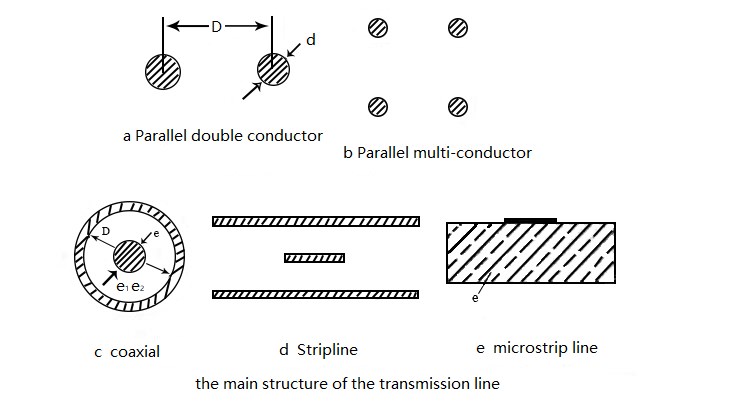
RF (Radio Frequency) connectors are defined as detachable components that are usually attached to cables or equipment for the electrical connection of transmission line systems. It can be seen from this definition that it has the common feature of the connector: a "detachable element." The term "Transmission line system" refers to the microwave transmission system. The common transmission line structure is shown in the following figure:
Take the commonly used coaxial line as an example; the main mode of the coaxial line is the Transverse Electromagnetic (TEM) wave, and the field distribution is shown in the figure below:
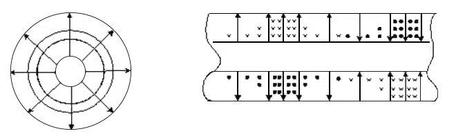
Field Distribution of a Coaxial Line
The electromagnetic wave transmitted by the RF connector is the energy derived from the in-phase and mutually perpendicular electric field and magnetic field in space. It is an electromagnetic field that propagates in the form of waves and exhibits the duality of wave and particle. The electric field direction, the magnetic field direction, and the direction of propagation are all perpendicular to each other, making them Transverse Electromagnetic waves (TEM).
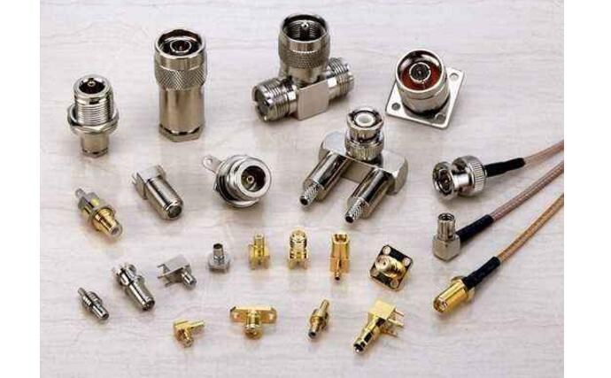
Various RF Connectors
Ⅱ Types of RF Connector
RF connectors are mainly classified based on their structure and intended application. The primary categories include:
RF Coaxial Connector: Primarily used to transmit Transverse Electromagnetic (TEM) waves. They are the most common type, featuring a central conductor, an insulating dielectric, and an outer conductor (shield).
RF Triaxial Connector (Tricaxial): Used for applications requiring higher shielding effectiveness, such as sensitive measurements or video signals. They feature an additional outer shield layer, providing better isolation from external noise.
Dual-Core Symmetric RF Connector (Twinaxial): Mainly used to transmit balanced signals, often for digital signals with a low transmission rate or for differential signaling. They consist of two inner conductors and one outer shield.
Key Performance Parameters of RF Coaxial Connectors include:
Characteristic Impedance: Typically 50 Ω (for RF/Microwave) or 75 Ω (for Video/CATV).
Frequency of Use: The maximum frequency at which the connector maintains specified performance.
Return Loss (VSWR): A measure of power reflected back due to impedance mismatch; a lower value is better.
Insertion Loss: The power lost through the connector; a lower value is better.
Isolation: The measure of signal leakage between two adjacent connectors.
RF Leakage: The amount of signal escaping the connector or external interference entering it.
Third-Order Intermodulation (PIM): Critical for high-power, multi-carrier systems (e.g., 5G base stations).
Common Materials and Plating: The RF connector is mainly composed of the outer conductor, inner conductor, and insulating support media.
Outer Conductor: Materials include stainless steel (passivation), copper alloy (nickel plating, ternary alloy plating), and brass (nickel or gold plating).
Inner Conductor: Copper alloy (gold plating or silver plating) is common for its high conductivity and corrosion resistance.
Insulation Support Media (Dielectric): PTFE (Polytetrafluoroethylene) is the gold standard for high-frequency performance due to its low dielectric constant. Other materials include PEI (Polyetherimide), LCP (Liquid Crystal Polymer), and sometimes polyethylene (PE) or polypropylene for lower-frequency, lower-cost applications.
Ⅲ Selection of RF Coaxial Connectors
The selection of RF coaxial connectors must balance technical performance requirements with economic factors. The performance must meet the requirements of the system's electrical equipment. In principle, the following four aspects should be considered:
Connector interface (e.g., SMA, SMB, BNC, N-Type)
Electrical performance, cables, and cable connection method
Termination form (e.g., PC board mount, cable mount, panel mount)
Mechanical structure and plating (e.g., military-grade, commercial-grade)
1. Connector Interface
The connector interface is usually determined by its application, but it must also meet specific electrical and mechanical performance requirements.
BNC Connector: Uses a bayonet-type connection for quick mating. Standard BNC is widely used for radio frequency and video applications with a frequency typically lower than 4 GHz, though high-performance versions can reach up to 12 GHz (e.g., HD-BNC). It is widely used in network systems, instrumentation, and computer interconnection.
TNC Connector: Similar to BNC but uses a screw-on coupling mechanism, which provides better performance under vibration conditions and can be used up to 11 GHz or higher.
SMA Connector: A sub-miniature screw connector widely used in military and civil fields such as aviation, radar, microwave communication, and digital communication. Its impedance is 50 Ω. Standard SMA is typically rated up to 18 GHz, though precision versions (like SMA 2.92mm or K-connectors) can extend the frequency range up to 40 GHz or more.
SMB Connector: Smaller than SMA, featuring a snap-on/push-pull self-locking structure for quick connection. Standard SMB is typically used up to 4 GHz.
N-Type Connector: A medium-sized screw connector often using air as an insulating material for low cost. Standard N-Type connectors are rated up to 11 GHz, with precision versions reaching 18 GHz or even 26.5 GHz (e.g., 7/16 DIN). It is commonly used in regional networks, media transmission, and test instruments.
BMA Connector: Used for blind-mate connection of low-power microwave systems up to 18 GHz.
Modern High-Frequency Connectors: For modern applications like 5G and 6G, new connector types have become prevalent:
2.92mm (K), 2.4mm, 1.85mm (V), and 1.0mm: These are precision connectors designed for millimeter-wave frequencies, supporting operations up to 40 GHz, 50 GHz, 67 GHz, and 110 GHz, respectively. They are crucial for high-speed test and measurement equipment and 5G/6G systems.
4.3-10 Connector: A modern, smaller alternative to the 7/16 DIN, designed for high-density installations in cellular base stations, offering excellent PIM performance and a smaller footprint.
2. Electrical Performance, Cable, and Cable Connection
A. Impedance
The connector and the cable must match the characteristic impedance of the system (typically 50 Ω or 75 Ω). Impedance mismatch will cause signal reflections and increase the Voltage Standing Wave Ratio (VSWR), leading to system performance degradation. Note that not all connector interfaces conform to both 50 Ω and 75 Ω; for example, SMA is almost exclusively 50 Ω.
B. Voltage
The maximum withstand voltage of the connector must not be exceeded during use to prevent dielectric breakdown.
C. Maximum Operating Frequency
Each connector has a maximum operating frequency limit, determined by its physical dimensions and the properties of the dielectric material. As frequencies increase, the connector's geometry must become more precise and smaller to prevent unwanted wave modes (higher-order modes) from propagating, which cause signal distortion and high loss.
D. Cable Types
Flexible Coaxial Cable: The most common type, featuring a braided outer conductor (shield). The flexibility is an advantage, but the shielding effectiveness can degrade at higher frequencies. The shielding effect depends on the braid density and thickness.
Semi-Rigid Coaxial Cable: Replaces the braid with a solid tubular outer shell (usually copper). This effectively compensates for the braided cable's poor shielding at high frequencies, offering superior shielding and lower loss. They are used at high frequencies but are not flexible.
Conformable Coaxial Cable: A hand-bendable alternative to semi-rigid cable, using a flexible metal braid or foil shield that can be shaped and will hold its shape.
E. Cable Connection (Termination)
There are two main installation methods for connectors:
Solder and Crimp: The center conductor is soldered, and the outer shield is crimped. This is a common, reliable method.
Solder/Crimp and Crimp/Crimp: The center conductor is crimped, and the shield is crimped. Crimping is increasingly popular due to its high efficiency, reliable termination performance, and the ability of specialized crimping tools to ensure consistency for every cable termination point. The combination of soldering the center conductor and crimping the shield remains a popular, reliable choice.
3. Termination Form
The connector can be used for RF coaxial cables, printed circuit boards (PCBs), and other connection interfaces. A certain form of connector is typically matched to a certain type of cable. For instance, small-diameter cables are connected to small coaxial connectors such as SMA, SMB, and SMC.
PC Board Termination: Connectors for PCBs come in various forms:
Through-Hole (THT): Pins are inserted through holes and soldered on the opposite side.
Surface Mount (SMT): Connectors are soldered directly onto the PCB surface. This is the dominant trend for high-volume, miniaturized applications (see Section Ⅳ).
Edge Launch: Designed to transition the signal from the coaxial line directly to a microstrip or stripline on the PCB edge, offering superior high-frequency performance.
4. Mechanical Structure and Plating Layer
The mechanical structure and material choices significantly impact the connector's price, durability, and performance.
Military Standard (MIL-SPEC): Manufactured according to standards like MIL-C-39012, typically using all-machined copper parts, PTFE insulation, and gold plating on both inner and outer conductors. This offers the most reliable performance and ruggedness.
Commercial Standard: Uses more cost-effective materials such as brass castings, polypropylene insulation, and often nickel or silver plating. While cheaper, the performance and mating cycle life are generally lower than MIL-SPEC.
Plating: The choice of plating is crucial for conductivity, corrosion resistance, and intermodulation performance.
Gold Plating: Preferred for the inner conductor due to its low resistance, excellent corrosion resistance, and stable contact resistance, especially vital for high-frequency and high-mating-cycle applications.
Silver Plating: Offers excellent conductivity but is prone to tarnishing (oxidation), which can degrade performance over time.
Nickel Plating: Often used for the outer conductor for its hardness and corrosion resistance, providing a durable, cost-effective finish.
Ⅳ The Future Development of RF Coaxial Connectors
Since the appearance of UHF series connectors in the 1930s, the RF coaxial connector has become an indispensable key component in communication equipment, weapon systems, instrumentation, and home appliances. With the continuous development of wireless communication standards (e.g., 5G, 6G) and the Internet of Things (IoT), RF coaxial connectors are constantly evolving. The future development trends are increasingly focused on:
1. Miniaturization and High Density
The miniaturization of the entire system (portable devices, drones, medical equipment) requires components to be smaller, which also reduces material and transportation costs. This trend drives the use of smaller connectors.
The SSMB series and newer types like MMCX and SMP (push-on/blind-mate) are examples of miniaturized products widely used in new-generation communication equipment to achieve high installation density.
The 1.0/2.3 (Mini-DIN) self-locking connector is a compact, high-performance option for broadcast and telecommunications.
Ultraminiature RF connectors (e.g., U.FL, MHF) are essential for small form-factor devices like smartphones and IoT sensors.
2. High Frequency and Millimeter-Wave Performance
To achieve wider channel bandwidth and higher data rates, the operating frequency of systems is constantly increasing, moving into the millimeter-wave (mmWave) band (30 GHz to 300 GHz) for 5G and beyond.
Precision connectors like 2.92mm (K), 2.4mm, 1.85mm (V), and 1.0mm are now standard for high-speed test and measurement and mmWave systems.
Research is already focusing on connectors for the D-Band (110 GHz to 170 GHz) and G-Band (140 GHz to 220 GHz) to support future 6G systems.
3. Surface Mount Technology (SMT)
The adoption of SMT has greatly improved assembly automation and reduced product costs in the electronics industry.
Surface mount RF coaxial connectors, while structurally challenging, are becoming the mainstream way for small connectors to connect with microstrips and printed boards, especially in user terminal products like mobile phones and small wireless modules.
4. Multi-functionality and High Power
New connectors are integrating additional functions beyond simple electrical connection, such as filtering, phase shifting, attenuation, and detection.
High-Power Performance: New generation communication systems, particularly cellular base stations, require high-power, multi-channel transmission. This necessitates connectors with extremely low Passive Intermodulation (PIM) distortion. The 4.3-10 and 7/16 DIN series are examples of connectors designed for superior PIM performance.
The International Electrotechnical Commission (IEC) has formulated test standards for PIM, which is now a basic electrical performance index for high-power RF coaxial connectors.
In short, the RF coaxial connector will continue to develop rapidly with the evolution of wireless technology, becoming an even more critical component in the field of microwave and millimeter-wave transmission.
Ⅴ Frequently Asked Questions (FAQs)
Q: What is the difference between 50 Ω and 75 Ω connectors?
A: The impedance is determined by the ratio of the outer conductor diameter to the inner conductor diameter and the dielectric constant of the insulator. 50 Ω is the standard impedance for most RF and microwave applications, including wireless communication, data transmission, and test equipment, as it offers the best compromise between power handling and attenuation. 75 Ω is the standard for video (e.g., HD-SDI, analog video) and cable television (CATV) applications, as it provides the lowest signal attenuation (loss).
Q: Can I connect a 50 Ω connector to a 75 Ω cable?
A: While physically possible for some types (like BNC), it is strongly discouraged. The impedance mismatch will cause significant signal reflection and power loss (high VSWR), severely degrading system performance. Always match the connector impedance to the cable and system impedance.
Q: What is Passive Intermodulation (PIM)?
A: PIM is a form of signal distortion that occurs when two or more high-power RF signals mix in a non-linear junction, such as a poorly manufactured or dirty connector. This mixing creates new, unwanted frequencies (intermodulation products) that can interfere with the system's own received signals. PIM is a critical concern in multi-carrier systems like cellular base stations, and specialized low-PIM connectors (e.g., 4.3-10) are required.
Q: What is the highest frequency an RF connector can handle?
A: Standard commercial connectors like SMA are typically limited to 18 GHz. However, precision connectors such as the 1.0mm type are commercially available and designed to operate up to 110 GHz for test and measurement applications, pushing well into the millimeter-wave spectrum.
Ⅵ Update Information (2025)
This article, originally published in 2020, has been thoroughly reviewed and updated to reflect the current state of RF connector technology as of 2025. Key updates include:
Correction of Outdated Specifications: The maximum operating frequencies for common connectors like BNC (now up to 12 GHz for HD-BNC) and SMA (standard 18 GHz, precision up to 40+ GHz) have been corrected and clarified. The N-Type frequency limit has been updated to 18 GHz for precision versions.
Terminology Correction: The translation error "cable maggot part" in the cable connection section has been corrected to "cable termination point."
Inclusion of New Standards: The discussion on future development has been significantly expanded to cover the impact of 5G and 6G on the market, specifically highlighting the importance of millimeter-wave connectors (2.92mm, 2.4mm, 1.0mm) and low-PIM connectors (4.3-10).
New Section Added: A dedicated Frequently Asked Questions (FAQs) section has been added to address common user queries regarding impedance, PIM, and frequency limits.
Formatting: The entire article has been prepared for mobile-responsive HTML output with inline styling, as requested.
Article Recommended:
 UTMEL
UTMEL
We are the professional distributor of electronic components, providing a large variety of products to save you a lot of time, effort, and cost with our efficient self-customized service. careful order preparation fast delivery service
What is RF connector on a TV?
The RF (radio frequency) input on an LCD television is typically used to connect cable TV service to the set.
Since LCD TVs usually have three or more inputs, use the remote control to activate the input for the RF connection.
What are RF connectors used for?
RF (radio frequency) connectors are connectors that are designed to work at radio frequencies for signal transmission of products like radios, antennas, coaxial cables, etc.
Is RF cable same as coaxial?
As for Ethernet, don't get mixed up between the term “RF cable” and “coaxial cable.” Many people use them interchangeably, but “RF cable” just means that signals oscillating at radio frequencies (fast) can be contained within RF cable, and that is often what we also call coaxial cable.
What is K type RF connector?
2.92mm (K) Connectors are RF/Microwave coaxial connectors that operate mode-free up to 40 GHz. These connectors are compatible to mate with SMA and 3.5mm connectors. The 2.92mm connectors were originally introduced by Mario Maury in 1974 and then re-introduced by Wiltron in 1984 as the K connector.
Can you convert RF to HDMI?
The converter takes the analog signal from coax and converts it into a digital signal for HDMI. You take the HDMI feed from the converter and attach it to an HDMI input on your TV. You should now be able to set the satellite receiver as a source and watch TV.
 High-speed Connectors Shortage Outlook 2026: Supply, Lead Times, and Sourcing OptionsUTMEL16 July 2026359
Entering 2026, the electronics supply chain faces a bifurcated market. While standard connectors remain stable, high-speed interconnects, RF modules, and optical transceivers experience severe shortages driven by rapid AI infrastructure growth. To mitigate these bottlenecks, engineering and procurement teams must adopt proactive design-for-availability strategies, utilize multi-footprint layouts, and leverage alternative global sourcing channels like UTMEL to secure critical BOM components.
Read More The Introduction to USB Type-C Pin Signal and PCB LayoutUTMEL03 December 202127073
Hello everyone. Welcome to the new post today. USB Type-C is a smaller-volume USB interface standard than Type-A and Type-B. It can be used on a PC (master device) as well as external devices (slave devices, such as mobile phones).
Read More Everything You Need to Know about ConnectorsUTMEL07 September 20218518
Electrical connectors, as key components for current or signal connections, are also an important part of the industrial system. Connectors can be as huge as airplanes and rockets or as small as mobile phones and televisions, forming bridges between circuits or other components and serving as electric current or signal links.
Read More Network Interface Card: Types, Functions and Buying GuideUTMEL17 August 202110735
Network Interface Card (NIC, also known as a network interface controller) is one of the most basic components in the local area network. It is the hardware device connecting the computer and the network. Whether it is a twisted pair connection, a coaxial cable connection, or an optical fiber connection, data communication must be realized with the help of a network interface card.
Read More?") What is Universal Serial Bus (USB)?UTMEL12 June 202612870
What is Universal Serial Bus (USB)?UTMEL12 June 202612870Universal Serial Bus (USB) is a serial bus standard and a technical specification for input and output interfaces. It is widely used in information communication devices. The latest generation is USB4, and its transmission speed is 40Gbit/s, the three-stage voltage is 5V/12V/20V, the maximum power supply is 100W.
Read More
Subscribe to Utmel !
![IPC-610BP-00LBE]() IPC-610BP-00LBE
IPC-610BP-00LBEAdvantech Corp
![IPC-611MB-00XBE]() IPC-611MB-00XBE
IPC-611MB-00XBEAdvantech Corp
![IPC-610BP-00XFCE]() IPC-610BP-00XFCE
IPC-610BP-00XFCEAdvantech Corp
![IPC-610MB-00XFCE]() IPC-610MB-00XFCE
IPC-610MB-00XFCEAdvantech Corp
![IPC-611BP-00XBE]() IPC-611BP-00XBE
IPC-611BP-00XBEAdvantech Corp
![IPC-610MB-50HBE]() IPC-610MB-50HBE
IPC-610MB-50HBEAdvantech Corp
![PCE-3B04-03A1E]() PCE-3B04-03A1E
PCE-3B04-03A1EAdvantech Corp
![ACP-1010BP-00BE]() ACP-1010BP-00BE
ACP-1010BP-00BEAdvantech Corp
![ACP-4000MB-00CE]() ACP-4000MB-00CE
ACP-4000MB-00CEAdvantech Corp
![AIMC-3200-00A1E]() AIMC-3200-00A1E
AIMC-3200-00A1EAdvantech Corp


