10 Details to Improve the Anti-Interference Ability of MCU
Ⅰ. Preface
The application of single-chip microcomputers in the domains of household appliances, industrial automation, production process control, and intelligent instrumentation has grown in tandem with the development of single-chip microcomputers.
Various electrical equipment in the same power system, on the other hand, is intimately related to one another via electrical or magnetic connections and influences one another. Much electrical equipment will be affected by electromagnetic oscillations induced by changes in operating modes, failures, switching activities, and so on.
This puts our single-chip microcomputer system's reliability and safety in jeopardy. The single-chip measurement and control system must perform consistently and reliably for an extended period of time; otherwise, the control error will increase, and in severe circumstances, the system would malfunction, resulting in significant losses.
As a result, the single-chip microcomputer's anti-interference problem has become a concern that cannot be overlooked.
Ⅱ. The influence of interference on the MCU application system
2.1 Increased measurement data error
Interference infiltrates the input channel of the analog signal of the single-chip microcomputer system's measurement unit and superimposes itself on the measurement signal, increasing the data collection error. Detecting weak signals, interference signals, and even overwhelming measurement signals is especially important.
2.2 Control system failure
The single-chip microcomputer's control signal is usually determined by the state input signal of certain conditions and the logic processing result of these signals. If these input status signals are disrupted, erroneous status information is introduced, the output control error or control failure will grow.
2.3 Affecting MCU RAM memory and E2PROM, etc.
To avoid interference and data degradation in a single-chip microcomputer system, programs, tables, and data are stored in the program memory EPROM or FLASH. Data in the on-chip RAM, external RAM, and E2PROM, on the other hand, may be affected by external interference and alteration.
2.4 The program runs abnormally
External interference can force the system to reset repeatedly, disrupting the program's usual operation. The regular operation of the program will be ruined if external interference causes the PC value of the program counter of the single-chip microcomputer to change.
Because the erroneous PC value is arbitrary, the program will run a sequence of useless instructions before entering an "endless loop," resulting in major output confusion or crashes.
Ⅲ. How to improve the anti-interference ability of the equipment?
3.1 Solve the interference from the power side
A DC power supply is required for each unit in a single-chip microcomputer system, and the DC power supply is typically generated after the AC power from the mains grid has been transformed, rectified, filtered, and stabilized. As a result, numerous power supply interference s will be introduced into the system.
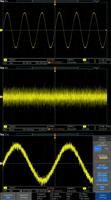
Furthermore, because the AC power is shared, the electronic devices will interfere with each other through the power supply. so power interference must be suppressed. The following are the most common types of power interference:
1. High-frequency interference (conducted disturbance) in the power cord
The power supply line acts as a receiving antenna, coupling high-frequency interference signals emitted by lightning, arcs, and radio stations to the secondary of the power transformer, causing interference to the single-chip system.
Solve this type of interference by adding a filter to the interface or using an isolated power module, which is commonly done through interface protection.
2. Transient noise generated by inductive load (EFT)
When a large-capacity inductive load is cut off, a large current and voltage change rate is generated, resulting in transient noise interference. which is the most common type of electromagnetic interference, To solve this type of interference. shielded wire and double glue wire are commonly used, as well as filter processing in the power and signal interfaces.
Both of these methods must be used with a well-grounded system, as well as a well-grounded filter and interface filter circuit, in order to efficiently bleed interference,
Ⅳ. Analog signal sampling anti-interference technology
One or more analog signals are sampled and transformed into digital signals for processing through A/D in a single-chip application system.
To enhance measuring accuracy and consistency;
To guarantee that the sensor's conversion accuracy is maintained;
The sensor power supply's stability;
Examine the amplifier's stability.
The reference voltage for A/D conversion is stable;
To keep external electromagnetic induction noise from interfering;
Weak helpful signals can be totally drowned by useless noise signals if they are not handled properly.
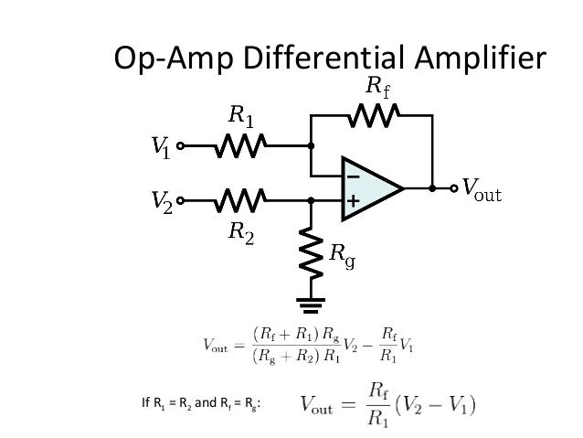
In real-world applications, a differential input measurement amplifier can be employed, a shielded double-glued cable can be used to convey the measurement signal, or a voltage signal can be converted to a current signal and resistance-capacitance filtering techniques can be used.
Ⅴ. Anti-interference technology of digital signal transmission channel
The digital output signal can be used as the driving signal for system-controlled equipment (like a relay), while the digital input signal can be utilized as the device's return answer and command signal (such as a travel switch, a start button, etc.).
One of the main avenues via which external interference enters the SCM system is the digital signal interface.
Transmission line shielding technologies, such as the use of shielded wire, double glue line, and other anti-jamming methods employed in the process of digital signal input/output include: Use signal isolation measures; Reasonable grounding. Because the digital signal generates common impedance interference during the level conversion process, selecting the right grounding point can effectively reduce ground noise.
Ⅵ. Hardware monitoring circuit
It is necessary to configure a hardware monitoring circuit in a single-chip microcomputer system in order to assure the system's reliable and stable operation as well as to improve its anti-interference capacity. The functions of the hardware monitoring circuit include the following:
Power-on reset: to ensure that the system can be properly started when it is turned on.
A reset signal is created to reset the system when the power fails or the voltage falls below a specified voltage value.
An alarm indication signal or an interrupt request signal will be sent if the power supply voltage is abnormal.
When the CPU encounters interference or the software runs erratically and generates a "deadlock," use the hardware watchdog to reset the system.
Ⅶ. Reasonable wiring of PCB circuit
The anti-interference ability is heavily influenced by the quality of the PCB board design. As a result, while designing a PCB, the general principles of PCB design must be observed, as well as the anti-interference design standards. The following sections concentrate on two points:
1. Placement of key components
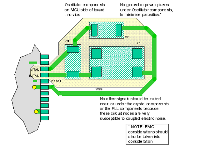
In terms of device layout, as with other logic circuits, the devices that are related to each other should be positioned as near together as possible to get a better anti-noise effect.
The clock generator, crystal oscillator, and the CPU 's clock input are all susceptible to noise, so they should be close together; the CPU reset circuit and hardware watchdog circuit should be as close to the corresponding pins of the CPU as possible; and noise-prone devices and high-current circuits should be kept as far away from logic circuits as possible.
2. Correct connection of the ground wire of the D/A and A/D conversion circuit
Digital ground and analog ground are provided via the D/A, A/D, and sampling chips, which all have equivalent pins.
All devices' digital and analog grounds must be linked independently in the circuit design, although the digital and analog grounds are only connected at one point. Shielding protection, which can be employed to isolate space radiation, is also an option.
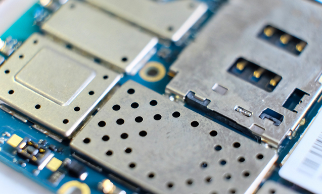
High-noise components (such as variable frequency power supplies and switching power supplies) can be encased in a metal box to prevent noise source interference with the single-chip microprocessor. A shielding cover can be added and grounded to the parts that are easily interfered with, allowing the interference signal to be short-circuited to the ground.
Ⅷ. Principles and methods of software anti-interference
Although hardware anti-jamming methods have been included, the causes of the interference signal are complex and unpredictable, making it impossible to assure that the system is totally free of interference,
As a result, software anti-jamming technology is frequently employed to enhance hardware anti-jamming measures as an auxiliary method to hardware measures. The software anti-jamming technology is extensively utilized in the system because it is simple, versatile, convenient, and low-cost.
1. Digital filtering method
On the basis of multiple sampling of analog signals, digital filtering is the process of obtaining data that is closest to the true value using software algorithms. The authority parameters of the digital filtering algorithm can be selected, and its effect is often not reached by the hardware filtering circuit.
2. The repeated detection method of the input signal
The input signal's interference is a series of discrete spikes superimposed on the effective level signal, with a very brief action time.
When there is input interference in the control system and the hardware cannot successfully suppress it, the software can be utilized to repeat the detection procedure until the acquisition results of two or more consecutive times are completely consistent.
If the signal is constantly changing, an alarm signal can be triggered when the maximum number of times has been achieved. This input method can be used to receive signals from various switch-type sensors, such as limit switches, travel switches, operation buttons, and so on.
A broader interference can be dealt with by inserting a delay between successive data collections.
3. Refresh method of output port data
The switch output software's anti-interference design primarily employs the approach of repeated output, which is an effective measure for improving the output interface's anti-interference performance. These safeguards are required for control signals generated by latches.
The data is output repeatedly in the shortest time feasible, and the right information arrives before the equipment impacted by the interference has time to respond, allowing misoperation to be avoided in real time. A data buffer for the output data can be built in the program's structure, and the data can be output in the program's periodic loop.
It is not possible to transfer data in this manner repeatedly for incremental control equipment. Only through the detection channel can the correctness of the data transmission be determined from the equipment's feedback information. The working mode control word and the output status word are regularly set together to make the output module work consistently when executing the repeated output function for the programmable interface chip.
4. Software interception technology
The repercussions will be more catastrophic and the system will collapse if the interference that enters the single-chip microcomputer system acts on the CPU,
The most common issue is breaking the state of the program counter PC, which causes the program to hop from one area to another, or to "fly arbitrarily" in the address space, or to fall into a "definite loop."
Software interception technology can intercept "random flying" programs or remove the program's "definite loop," bringing it back on track and directing it to the specified program entry.
5. "Software watchdog" technology
The PC is agitated and uncontrollable, leading the program to "fly in disorder" or fall into a "definite loop." When software interception technology fails to free an out-of-control program from the "endless loop" problem, the program monitoring technology WDT TIMER (WDT), also known as watchdog technology, is commonly employed to free the program.
WDT is a software and hardware combination that prevents program runaway. The hardware body of the device is a counter or monostable that generates timing T. The counter, sometimes known as a monostable, is essentially self-contained, with its timing output connected to the CPU's reset line. The CPU is in charge of clearing its timing.
Under normal circumstances, the CPU periodically clears the WDT after the program starts it, preventing WDT timing overflow and having no effect similar to sleep. When the WDT time overflows, its output resets the system to avoid the CPU from being paralyzed owing to temporary interference condition. When the WDT timing overflows, its output resets the system to prevent the CPU from being paralyzed due to temporary interference status.
Ⅸ. Summary
The problem of electromagnetic interference has grown in importance as single-chip microcomputer systems have become more widely used and as technology has advanced. The single-chip application technology's key priority include the promotion of existing and mature anti-jamming technologies, as well as the study of new anti-jamming technologies and new directions. The stability and dependability of the single-chip application system may be considerably enhanced if the electromagnetic compatibility of the equipment is thoroughly considered during the design and application process, and interference is minimized by various technical means.
1. How to solve the problem of anti-interference of MCU?
The commonly used methods to solve the problem of MCU interference are filtering, shielding, isolation and grounding. Filtering is the installation of harmonic suppression devices such as filters.
2. How to solve the frequency signal interference of single-chip microcomputer?
Generally speaking, there are two solutions to interference: filtering and shielding. Filtering can be connected in parallel with a 10uF tantalum capacitor and a 104 monolithic capacitor between the power supply near the chip and the ground. The shielding measures can be used to coat a large area of the device with a large area of copper. Grounding, crystal case grounding, etc. are all effective anti-interference methods.
3. What kind of interference caused by the single-chip microcomputer will cause abnormal operation?
1. Strong electric field or strong magnetic field
2. Humidity and temperature, for example, civilian single-chip microcomputers may not work well in Harbin in winter.
3. Lightning strikes and strong pulse interference may crash or reset.
 Getting Started with Arduino: What is Arduino and How to Use Arduino BoardsUTMEL28 September 20234762
Arduino is an open-source electronics platform that includes software and programmable circuit boards, allowing beginners to build electronic projects by writing simple code. The article provides an overview of Arduino, including different board types, basic components, how to use the boards, and project ideas like an automated plant watering system.
Read More Arduino vs. Raspberry Pi: A Detailed ComparisonUTMEL24 April 20253402
Hello everyone, welcome to the new post today.This guide is going to talk in detail about Arduino vs. Raspberry Pi to clarify their differences and help you pick the right board based on your needs.
Read More Electronic Components in the Smart Home SystemUTMEL24 April 20251123
Electronic parts are the heart of every smart home system. These parts help devices talk, do tasks, and save energy. For instance, sensors notice motion or temperature changes. Microcontrollers use this data to do things like dim lights or turn on alarms.
Read More Software Tools for NXP Microcontroller DevelopmentUTMEL06 June 20251011
Discover how NXP microcontroller tools like MCUXpresso IDE, SDK, and Config Tools streamline coding, debugging, and hardware setup for embedded systems.
Read More VFD Driving Guide: What to Do When Your MCU Runs Out of Pins?UTMEL22 July 2025797
This comprehensive guide addresses a common challenge faced by electronics enthusiasts: driving Vacuum Fluorescent Displays (VFDs) when microcontrollers have insufficient pins. Sparked by a Reddit user's question about controlling a VFD with more segments than available MCU pins, the article explores the elegant solution of multiplexing technology.
Read More
Subscribe to Utmel !
![AA2.255KGA.00146]() AA2.255KGA.00146
AA2.255KGA.00146Apacer Memory America
![AA2.259FZA.001E9]() AA2.259FZA.001E9
AA2.259FZA.001E9Apacer Memory America
![AA2.255GGA.00146]() AA2.255GGA.00146
AA2.255GGA.00146Apacer Memory America
![SFSD256GN1AM1MT-E-7G-211-STD]() SFSD256GN1AM1MT-E-7G-211-STD
SFSD256GN1AM1MT-E-7G-211-STDSwissbit
![SFSD064GL1AM1MT-E-5E-211-STD]() SFSD064GL1AM1MT-E-5E-211-STD
SFSD064GL1AM1MT-E-5E-211-STDSwissbit
![SFSD016GN1AM1MT-I-5E-21P-STD]() SFSD016GN1AM1MT-I-5E-21P-STD
SFSD016GN1AM1MT-I-5E-21P-STDSwissbit
![SQF-S10Z2-64GCSBE]() SQF-S10Z2-64GCSBE
SQF-S10Z2-64GCSBEAdvantech Corp
![SFSD016GL1AM1MT-I-5E-21P-STD]() SFSD016GL1AM1MT-I-5E-21P-STD
SFSD016GL1AM1MT-I-5E-21P-STDSwissbit
![SFSD032GL1AM1MT-E-6F-21P-STD]() SFSD032GL1AM1MT-E-6F-21P-STD
SFSD032GL1AM1MT-E-6F-21P-STDSwissbit
![SFSD032GN1AM1MT-I-6F-21P-STD]() SFSD032GN1AM1MT-I-6F-21P-STD
SFSD032GN1AM1MT-I-6F-21P-STDSwissbit


