Analysis of Common Misunderstandings of Isolation Technology

Opto-Couplers Theory and Circuits
With the increased demand for dependable signal isolation in industrial, automotive, communications, and personal electronics applications, designers are increasingly turning to digital isolators rather than classic isolation technologies like optocouplers. Despite the widespread use of digital isolation, there are various misconceptions concerning its performance in comparison to optocouplers. Similarly, there are various misconceptions or myths about optocouplers' dependability and lifespan. I'll dispel some prevalent misconceptions about these two devices in this essay.
What is a digital isolator, and how does it work?
Let's take a look at the distinctions between these strategies first:
An optocoupler generates input-side current using a logic input, the LED transforms the signal to light, which is then transported to the other side via isolation and converted to an electrical signal by a photodetector.
Silicon-based CMOS technology with two integrated circuits and a high-voltage dielectric built into the silicon process is used in digital isolators. Digital isolators transport RF signals through a capacitor-based high-voltage silica dielectric barrier after converting digital signals to the high-frequency domain.
Optocoupler Misunderstanding 1: Optocouplers are very reliable
It's a frequent fallacy that optocouplers always fail with an "open" circuit when exposed to high voltages. Although optocouplers can fail in a variety of ways, depending on the distinct failure modes in high voltage systems, they can also fail in "shorted" circuits.
When the voltage delivered across the barrier exceeds the isolator's rated limitations, the isolation barrier can short-circuit for both optocouplers and digital isolators in the first failure scenario. Texas Instruments (TI) put the first failure mode to the test in its lab; the white paper "Understanding Failure Modes in Isolators" covers the short-circuit failure observations in detail.
The second failure mode, in which the circuit is destroyed by high voltage and high current inside the isolator, can result in a faulty open condition. These high voltage spikes can damage the circuit further, rendering it unusable, but the isolation barrier remains intact.
A high voltage event on an optocoupler is shown in Figure 1a, and a comparable event on a digital isolator is shown in Figure 1b. Various degrees of degradation can occur depending on the type of high pressure event and the strength of the barrier. An isolator that meets or exceeds electrical safety standards must be chosen to prevent short-circuit issues produced by the first failure scenario.

Figure. 1 Cross-Section of (a) Optocoupler Side and (b) Digital Isolator Side during High Voltage Accident.
Optocoupler Misunderstanding 2: The life of an optocoupler is predictable with little change
It is vital, as with other electronic designs, to ensure that the IC will last the product's entire life cycle. Isolation devices are extremely important since they safeguard signals across multiple voltage domains. While you might anticipate two identical optocouplers to have very comparable high-voltage lifetimes, the high-voltage performance of various devices might vary greatly. This is mainly due to the optocoupler's isolation barrier being produced during the packing stage.
Isolation barriers for digital isolators are often built during the more strictly controlled silicon chip manufacturing process. The difference in high voltage life and variation is depicted in Figure 2, where the high voltage life is longer and the TI digital isolators used in this test are more closely spaced. See the white paper "Improving System Performance by Replacing Optocouplers with Digital Isolators" for more information.
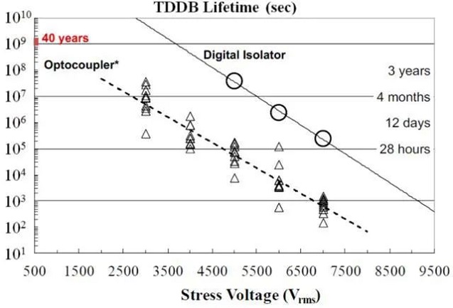
Figure. 2 Time-Dependent Dielectric Breakdown Characteristics of Optocouplers and Digital Isolators.
Optocoupler Misunderstanding 3: The optocoupler Datasheet specification will strictly conform to the service life of the device
You might not realize it, but the light output of an LED in an optocoupler declines over time, affecting characteristics like the current transfer ratio (CTR). Over time, the plastic inside the optocoupler turns yellow, allowing less light to flow through the isolation barrier and limiting transmission even further. The CTR will eventually decline to the point that the device will stop working properly, leading in high failure rates and short mean time between failures.
To accommodate for projected degradation over time, designers frequently include margins in their designs, which can result in higher initial power usage. Because these concerns aren't typically addressed in optocoupler datasheets, it's difficult to factor them into isolation designs. For example, TI's digital isolators are manufactured in a carefully regulated environment, and the Datasheet considers minimum and maximum specification burn-in to assist set performance expectations over the device's lifetime.
Optocoupler Misunderstanding 4: The maximum operating temperature of the optocoupler is higher
The maximum operating temperature for most optocouplers is 85°C. Although higher temperature rated optocouplers are available, they have fewer options and are often more expensive. Digital isolators, on the other hand, can easily withstand operating temperatures of up to 125°C. Digital isolators like TI's Grade-0 certified ISO7741E-Q1 assist ensure dependable system performance at high peak ambient temperatures for automotive systems requiring temperature support up to 150°C. Lower temperature ratings can be troublesome in high-temperature designs when every component must perform consistently over 110°C. Otherwise, the system's performance or the device's life expectancy may be harmed.
Optocoupler Misunderstanding 5: No primary side power supply means lower power consumption
When designing a system to save energy, it's crucial to think about how the isolator's input is powered. Current inputs drive optocouplers, while voltage inputs - CMOS or transistor logic - drive digital isolators.
Through series resistors that control voltage and current, optocouplers can drive digital device inputs such as microcontrollers, analog-to-digital converters, and digital-to-analog converters. To activate the LEDs and fulfill product lifetime reliability, input currents as high as 10 mA are necessary, which can result in considerable power dissipation at the input.
Digital isolators, such as the TI ISO7041, typically have a standby current of less than 10 A at the input. Figure 3 depicts the ISO7041's current consumption vs data rate. In this test, the device's four channels draw less than 20 amps.
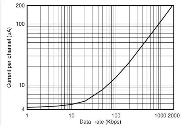
Figure. 3 Current Consumption Versus Data Rate for the ISO7041.
Digital isolator Misunderstanding 1: A digital isolator with a smaller DTI indicates weaker isolation
The distance to insulation (DTI) of an isolator refers to the thickness or distance between the high and low voltage sides of the dielectric used for insulation. DTI is the distance between the LED and the photodetector in optocouplers. DTI is the distance between the two plates of the capacitor in capacitance-based digital isolators.
There is a misperception that all isolators must have a DTI greater than 0.4 mm to achieve today's stringent reinforced isolation certification criteria because of earlier safety regulations that set minimum DTI limits based on optocoupler technology. In actuality, the isolator barrier's strength is a mix of DTI and dielectric material.
Because optocouplers have a lower dielectric strength, a higher DTI is necessary. Digital isolators based on capacitors have a higher dielectric strength and can support reinforced isolation with DTI down to 21 m.
Organizations that oversee equipment operating safety standards have taken this into account over time and amended regulations to allow for thinner dielectrics dependent on the technology being examined. The dielectric strength of several insulating materials is listed in Table 1.

Table. 1 Dielectric Strength of Common Insulating Materials.
Digital isolator Misunderstanding 2: The cost of digital isolators is substantially higher than that of optocouplers.
Despite the myth's historical relevance, digital isolator technology has progressed dramatically in the last decade, allowing for improved performance at reduced costs. The ability to accomplish multiple channel counts in the same package also contributes to lower overall system density and cost. The ISO6741, for example, provides four channels of reinforced isolation in a single box, resulting in a reliable isolation solution at a low cost per channel.
Digital isolator Misunderstanding 3: Digital isolator integration and saving board space comes at a price
One of the most appealing features of digital isolators is their ability to combine several system requirements into a single unit. GE Controller Area Network, RS-485, I2C, and LVDS signals are examples of isolated interfaces. You may be concerned that purchasing a digital isolator with an integrated transceiver will put a strain on your budget, but the truth is that an integrated digital isolator has numerous advantages over discrete optocoupler options.
The cost of the various discrete components (resistors, capacitors, diodes, Schmitt buffers, transistors) and their PCB space is the major disadvantage of discrete optocoupler solutions. The dimensions of the optocoupler and the ISO1500 integrated RS-485 digital isolator are shown in Figure 4. See the technical article "The Hidden Cost of Optocouplers for Isolated RS-485 Designs" for more information on this comparison.
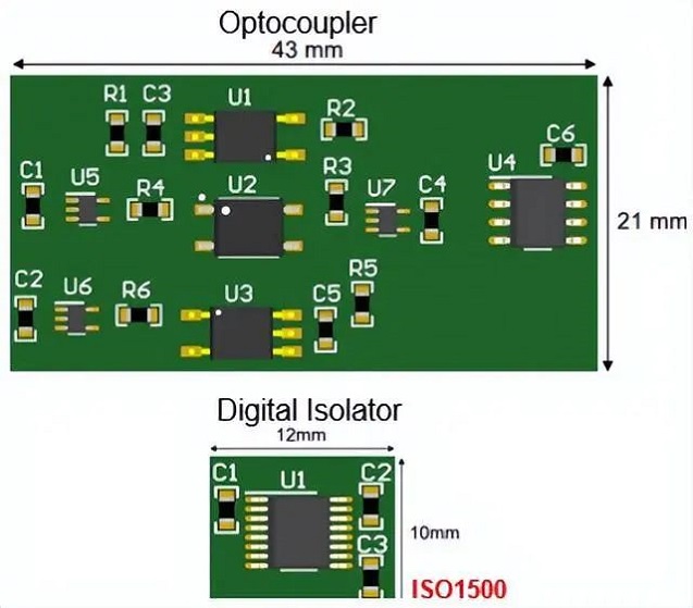
Figure. 4 PCB Comparison between RS-485 Discrete and Fully Integrated Isolation Schemes
In conclusion
Over the last few decades, digital isolation has gone a long way and is now the isolation option of choice for many designers. When your design calls for a trustworthy signal isolation solution, keep the misconceptions and truths discussed in this article in mind.
1. What is a bidirectional optocoupler?
A bidirectional optocoupler is an optocoupler whose interface endpoints are not divided into positive and negative poles.
2. What is an optocoupler?
Optical coupler equipment (OCEP) is also called opto-isolator or opto-coupler. It is a device that transmits electrical signals with light as a medium, usually encapsulating the emitter (infrared light-emitting diode LED) and the light receiver (photosensitive semiconductor tube, photoresistor) in the same tube.
3. How to judge the quality of the optocoupler?
Use the PN junction measurement end of the digital multimeter, the red test lead "battery + pole" is connected to the "1" end of the optocoupler, and the black test lead "battery - pole" is connected to the "2" end of the optocoupler (even if the light-emitting diode of the optocoupler is conducting in the forward direction). ), use another meter to measure the resistance of "3" and "4" terminals, disconnect or connect the input terminal (light-emitting diode terminal), the resistance of the output terminal should have a large change, indicating that it is good to change the optocoupler. In addition, the multimeter at the LED end can be replaced by a battery string current limiting resistor.
 The Introduction to Common Tools and Using Methods of Fiber OpticUTMEL07 January 20226518
The building and maintenance of optical cables in the intelligent industry has gradually expanded with the rapid expansion of the Internet of Things and 5G technologies, resulting in an increase in demand for various optical fiber tools. Cutting shears, for example, come in a variety of shapes and sizes, and each tool serves a different purpose. Do you have any experience with them? When should you utilize certain fiber optic tools?
Read More What are Fiber Optic Patch Cables?UTMEL11 February 20227727
Hello everyone, I am Rose. Today I will introduce fiber optic patch cables to you. Optical fiber communication, as an emerging technology, has become one of the main pillars of modern communication and plays a critical role in modern telecommunication networks, thanks to the rapid growth of traffic data.
Read More Basis of Fiber Optic and Fiber Optic CommunicationUTMEL22 October 20213380
Hello everyone, I am Rose. Today I will introduce fiber optic to you. Fiber Optic is a type of glass or plastic fiber that can be utilized to transmit light. It is mostly used for communication. This article will show you the basic knowledge of fiber optic and fiber optic communication.
Read More The History of MicroscopeUTMEL21 October 20217339
Hello, everyone. I am Rose. Today I will show you the history of microscopes. The microscope is used to magnify tiny objects into instruments that can be seen by human eyes. Microscopes are divided into optical microscopes and electron microscopes.
Read More What is VCSEL?UTMEL28 October 20219784
Hello everyone, I am Rose. I welcome you on board, today I will introduce VCSEL to you. The Vertical-Cavity Surface-Emitting Laser (VCSEL, or Vertical-Cavity Surface-Emitting Laser) is a semiconductor whose laser is emitted perpendicular to the top surface. It differs from an edge-fired laser, which emits the laser from the edge.
Read More
Subscribe to Utmel !
![PDA54-11SURKWA]() PDA54-11SURKWA
PDA54-11SURKWAKingbright
![SIM-040ST]() SIM-040ST
SIM-040STROHM Semiconductor
![DL1BKB5]() DL1BKB5
DL1BKB5Schneider Electric
![NTE30143-EW]() NTE30143-EW
NTE30143-EWNTE Electronics, Inc
![NTE30142-EW]() NTE30142-EW
NTE30142-EWNTE Electronics, Inc
![95-21SURC/S530-A3/TR10]() 95-21SURC/S530-A3/TR10
95-21SURC/S530-A3/TR10Everlight Electronics Co Ltd
![HFBR-2416Z]() HFBR-2416Z
HFBR-2416ZBroadcom Limited
![95-21SYGC/S530-E2/TR10]() 95-21SYGC/S530-E2/TR10
95-21SYGC/S530-E2/TR10Everlight Electronics Co Ltd
![95-21UYC/S530-A3/TR10]() 95-21UYC/S530-A3/TR10
95-21UYC/S530-A3/TR10Everlight Electronics Co Ltd
![HSMM-C190]() HSMM-C190
HSMM-C190Broadcom Limited


