Basis of Fiber Optic and Fiber Optic Communication

How Does LIGHT Carry Data? - Fiber Optics Explained
| Topics covered in this article: |
| Ⅰ. What is Fiber Optic |
| Ⅱ. The Working Principle of Fiber Optic |
| Ⅲ. The Development History of Fiber Optic Communication |
| Ⅳ. The Characteristics of Fiber Optic Communication |
Ⅰ. What is Fiber Optic
Fiber Optic is a type of glass or plastic fiber that can be utilized to transmit light.

It is mostly used for communication. The fiber optic utilized in communication today is essentially a silica optical fiber, with high-purity silica glass, especially silicon dioxide, as its principal component (SiO2).
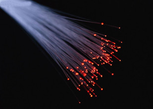
Fiber optic communication systems use light waves to transfer information via optical fibers to achieve the goal of communication.
▎Dispersion of fiber optic
Causes of fiber dispersion
The optical signal in an optical fiber is made up of several different components. Because each frequency component or mode component of the signal propagates at a different speed, there will be a time delay difference between the different components after a certain distance along with the optical fiber, causing the transmission signal waveform to change. Fiber dispersion is a phenomenon that causes pulse broadening and distortion.
Influence of fiber dispersion
Inter-symbol interference is caused by fiber dispersion, which distorts and broadens the transmitted signal pulse. The inter-symbol interval must be raised to ensure communication quality, which means the signal's transmission rate must be reduced, limiting the optical fiber system's communication capacity and transmission distance.
Classification of fiber dispersion
Fiber dispersion can be classified as modal dispersion, material dispersion, waveguide dispersion, and polarization dispersion based on the sources of dispersion.
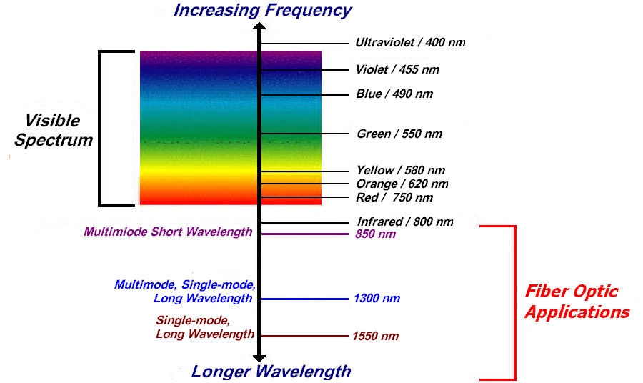
▎The electromagnetic spectrum of fiber optic
▎The loss of fiber optic
After the optical signal has been carried through the optical fiber, the loss of optical power occurs owing to absorption, scattering, and other factors.
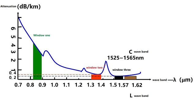
Schematic diagram of the attenuation of ordinary single-mode fiber with wavelength
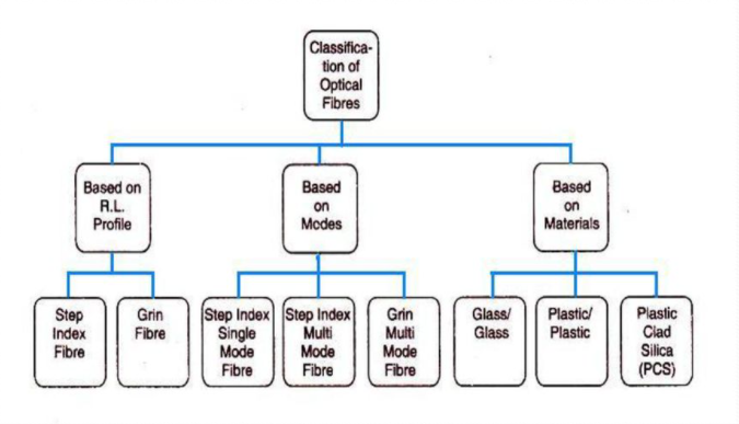
▎The classification of fiber optic
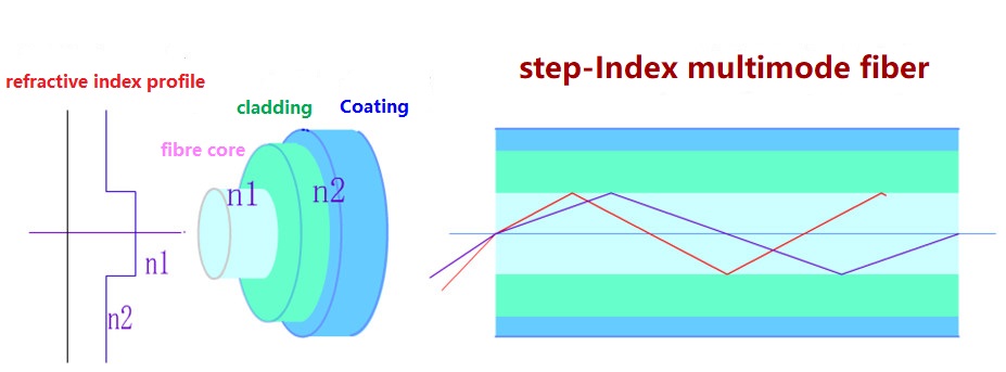
Step fiber
The refractive index distributions in the core and cladding areas are uniform, n1 and n2, respectively. The refractive index changes gradually (n2n1) at the boundary between the core and the cladding.

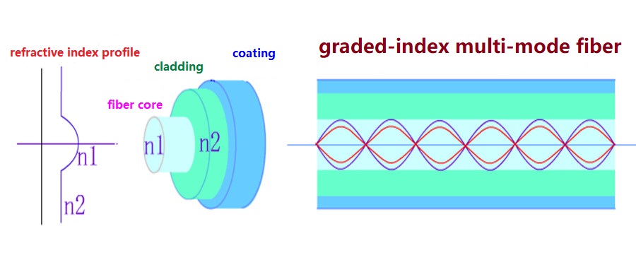
Graded fiber
The refractive index is highest (n1) along the fiber axis, but it gradually falls as the radial direction of the cross-section increases. It simply lowers to the refractive index n2 with the cladding region at the boundary between the core and the cladding.
MMF, multimode fiber
Multiple light modes can be transmitted. However, inter-mode dispersion is rather high, limiting the frequency of digital signal transmission, and it becomes more serious as distance increases.
SMF, single-mode fiber
Because just one mode of light may be communicated, the inter-mode dispersion is extremely low, making it ideal for long-distance communication.

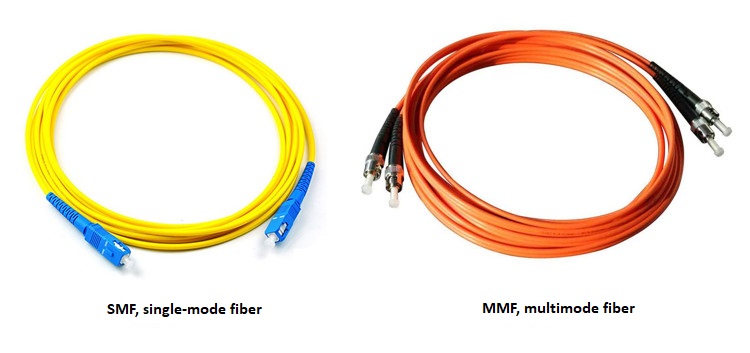

MMF VS SMF
▎Fiber optic interface
Optical fiber interfaces are classified as follows:
FC threaded circle (most used on patch panels)
ST circular snap-on type
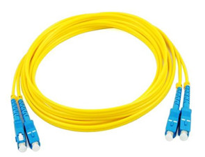
square type SC card-connected SC card-connected SC card-connected SC card-connected SC (most used on router switches)
The LC connector has a similar design to the SC connector, although it is smaller. MT-RJ square type, integrated one-head dual fiber transceiver
MPO/MTP type
BFOC type
DIN type
FDDI type
MU type

What exactly do terms like "FC/PC," "SC/PC," and "SC/APC" mean?
The part before "/" denotes the pigtail connector type; FC and SC are, as previously said, omitted; the part following "/" denotes the optical fiber connector cross-section process, i.e. the grinding method.
“PC: Physical Contact”:
It has a flat joint cross-section; in fact, it is micro-spherical grinding and polishing, which is the most extensively used in telecom equipment.
“APC”:
It grinds and polishes micro-spherical surfaces at an angle of 8 degrees. It is the most common model in radio and television, as well as early CATV. Its pigtail head has an angled end face that helps increase TV signal quality. The fundamental reason is that because the TV signal is analog light modulation, the reflected light returns along the original path when the coupling surface of the connector is vertical.
“UPC”:
The attenuation is lower than that of "PC," therefore it is commonly utilized for special-purpose equipment. For internal fiber jumpers in ODF racks, some foreign manufacturers employ FC/UPC, mostly to improve the ODF equipment's own indications.
▎Fiber optic module
Optical transceiver, or optical transceiver in full, is a critical component in optical fiber communication systems.
The following types of network equipment are typically included:
SFP(Small Form-factor Pluggable transceiver ):
SFP is a small package pluggable transceiver (LC interface) that can transmit data at speeds of 100, 155, 622, 1000, 1250, and 2500 Mbps.
GBIC (Gigabit Interface Converter):
Gigabit Ethernet interface converter (SC interface)
XFP(10-Gigabit small Form-factor Pluggable transceiver ):
10 Gigabit Ethernet interface small package pluggable transceiver (LC interface)
XENPAK(10 Gigabit EtherNet Transceiver PAcKage ):
10 Gigabit Ethernet interface transceiver package (SC interface)

▎Fiber splicing
Fusion splicing is a wiring technique that melts the optical fiber into a single piece using the heat created by the discharge between the electrode rods. It's broken down into two sections:
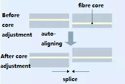
Fiber core alignment method
This is a fusion method in which the optical fiber's core wire is examined under a microscope, image processing is used to place the core wire's center axis, and the fiber is then discharged. For placement from two directions, a fusion splicing machine with a two-way observation camera is employed.
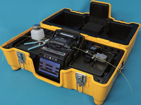
Fiber Fusion Splicer
Fixed V-groove alignment method
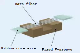
This is a fusion process in which the fibers are organized in a high-precision V-groove and the outer diameter is aligned using the aligning effect created by the surface tension of the melted fiber. The dimensional accuracy of the position of the optical fiber core has recently improved as a result of advancements in manufacturing technology, allowing for low-loss wiring to be produced.
This method is mostly used for one-time multi-core wiring.
Ⅱ. The Working Principle of Fiber Optic
Principle of Total Reflection
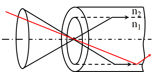
The angle of refraction is greater than the angle of incidence when the light beam is directed from the optically dense media to the optically thin medium, as illustrated in the picture.
If 0 is increased constantly, the refraction angle 1 can reach 90°, at which point 1 is referred to as the critical angle.
Total reflection occurs when light is directed from an optically dense media to an optically thin medium with an incidence angle larger than the critical angle.
Total reflection is used in fiber optics to convey optical signals.
Ⅲ. The Development History of Fiber Optic Communication
The "optical telephone" was invented by Alexander Graham Bell in 1880.
Charles Vernon Boys, a British physicist, created the first optical fiber in the laboratory in 1887.
Long glass strands were first produced in 1938 by the American Owens Illinois Glass Company and the Japanese Nitto Textiles Company.
Brian O'Brian, an optical physicist, invented the notion of cladding in 1951.
The first glass-clad fiber was created in 1956 by a University of Michigan student. To melt a glass tube with a low refractive index onto a glass rod with a high refractive index, he used a low refractive index glass tube.
Theodore Maiman demonstrated the first laser in 1960. People's interest in optical communication has been piqued as a result of this. Laser appears to be a very promising communication method that can solve the bandwidth problem. Experiments have begun in a number of laboratories.
Gao Kun, a British-Chinese researcher, first suggested the feasibility and technological technique of employing optical fiber for data transmission in 1966, laying the groundwork for modern optical communication—optical fiber communication.
Corning, a company based in the United States, created a quartz optical fiber with a loss of 20dB/km in 1970.
Bell Laboratories in the United States improved on this in 1973, lowering optical fiber loss to 2.5dB/km.
The optical fiber loss was lowered to 0.47 dB/km (wavelength 1.2m) by Nippon Telegraph and Telephone (NTT) in 1976.
Ⅳ. The Characteristics of Fiber Optic Communication
Huge communication capacity
An optical cable may theoretically transport 10 billion voice channels at once. Currently, the simultaneous testing of 500,000 voice channels has been successful, which is thousands or even hundreds of thousands of times greater than typical coaxial cables and microwaves.
Long Relay Distance
Optical fiber has a very low attenuation coefficient, which, when combined with appropriate optical transmission, optical receiving equipment, optical amplifier, forward error correction, and RZ code modulation technology, can achieve relay distances of thousands of kilometers, whereas traditional cable can only transmit 1.5 kilometers and microwave 50 kilometers, respectively.
Good confidentiality
Adaptable
It has the benefits of not being affected by powerful external electromagnetic fields, corrosion resistance, and so on.
Small size and lightweight
Rich sources of raw materials and low prices
1. Which fiber has better performance?
The core of the single-mode fiber is thin, so that the light can be directly launched to the center. It is recommended to use it when the distance is long; the optical signal in the multi-mode fiber propagates through multiple channels, and it is usually recommended to be used when the distance is short. In addition, the distance loss of single-mode signals is smaller than that of multi-mode signals.
2. What are the main advantages of optical fiber communication?
Optical fiber communication has many advantages: its transmission frequency bandwidth, large communication capacity; low transmission loss, long relay distance; thin wire diameter, light weight, raw material made of quartz, saving metal materials, conducive to the rational use of resources; insulation, anti-electromagnetic interference Strong performance; it also has the advantages of strong corrosion resistance, strong radiation resistance, good circumvention, no electric spark, small leakage, and strong confidentiality. It can be used in special environments or military.
3. What does splicing mean in optical fiber communication?
Fusion fiber is fusion splicing optical fibers, that is, welding optical fibers together.
The optical fiber fusion splicing technology mainly uses a fiber fusion machine to connect the optical fiber and the optical fiber or the optical fiber and the pigtail, and fuse the bare fiber and the fiber pigtail in the optical cable into a whole, and the pigtail has a separate optical fiber head.
 The Introduction to Common Tools and Using Methods of Fiber OpticUTMEL07 January 20226399
The building and maintenance of optical cables in the intelligent industry has gradually expanded with the rapid expansion of the Internet of Things and 5G technologies, resulting in an increase in demand for various optical fiber tools. Cutting shears, for example, come in a variety of shapes and sizes, and each tool serves a different purpose. Do you have any experience with them? When should you utilize certain fiber optic tools?
Read More What are Fiber Optic Patch Cables?UTMEL11 February 20227654
Hello everyone, I am Rose. Today I will introduce fiber optic patch cables to you. Optical fiber communication, as an emerging technology, has become one of the main pillars of modern communication and plays a critical role in modern telecommunication networks, thanks to the rapid growth of traffic data.
Read More Basis of Fiber Optic and Fiber Optic CommunicationUTMEL22 October 20213315
Hello everyone, I am Rose. Today I will introduce fiber optic to you. Fiber Optic is a type of glass or plastic fiber that can be utilized to transmit light. It is mostly used for communication. This article will show you the basic knowledge of fiber optic and fiber optic communication.
Read More The History of MicroscopeUTMEL21 October 20217084
Hello, everyone. I am Rose. Today I will show you the history of microscopes. The microscope is used to magnify tiny objects into instruments that can be seen by human eyes. Microscopes are divided into optical microscopes and electron microscopes.
Read More What is VCSEL?UTMEL28 October 20219714
Hello everyone, I am Rose. I welcome you on board, today I will introduce VCSEL to you. The Vertical-Cavity Surface-Emitting Laser (VCSEL, or Vertical-Cavity Surface-Emitting Laser) is a semiconductor whose laser is emitted perpendicular to the top surface. It differs from an edge-fired laser, which emits the laser from the edge.
Read More
Subscribe to Utmel !
![HSMF-C164]() HSMF-C164
HSMF-C164Broadcom Limited
![GL100MN1MP]() GL100MN1MP
GL100MN1MPSharp Microelectronics
![HSMC-A100-R00J1]() HSMC-A100-R00J1
HSMC-A100-R00J1Broadcom Limited
![APFA3010SEEZGQBDC]() APFA3010SEEZGQBDC
APFA3010SEEZGQBDCKingbright
![IR91-21C/TR7]() IR91-21C/TR7
IR91-21C/TR7Everlight Electronics Co Ltd
![SML-D15UWT86]() SML-D15UWT86
SML-D15UWT86ROHM Semiconductor
![HIR204C/H0]() HIR204C/H0
HIR204C/H0Everlight Electronics Co Ltd
![KAA3528ESGC]() KAA3528ESGC
KAA3528ESGCKingbright
![F5D2]() F5D2
F5D2ON Semiconductor
![17-215SYGC/S530-E2/TR8]() 17-215SYGC/S530-E2/TR8
17-215SYGC/S530-E2/TR8Everlight Electronics Co Ltd


