
 Product
 Brand
Brand Articles
 Tools
Tools
How to Select a Digital Isolator?

How to Select the Right Digital Isolator
Abstract: Digital isolator is a chip used to make the electronic system have high resistance isolation when signals and analog signals are transmitted, so as to realize the isolation between the electronic system and its users. The reason why designers introduce isolation is to meet safety regulations or reduce ground loop noise. Galvanic isolation ensures that data transmission is not through electrical connections or leakage paths, thereby avoiding safety risks. However, isolation brings limitations in terms of delay, power consumption, cost, and size. The goal of digital isolators is to meet safety requirements while minimizing adverse effects.
Catalog:
| I Classification of Digital Isolator |
| II Three elements of Choice |
| III Key Steps to Choose a Digital Isolator |
I Classification of Digital Isolator
According to the mode of transmission, digital isolator can be divided into:
1. Optical isolation
Optical coupling technology is the transmission of light on a transparent insulating isolation layer (for example air gap) to achieve isolation. The optical coupler generally consists of three parts: light emission, signal amplification, and light reception. The input electrical signal drives the LED to emit light of a certain wavelength, which is received by the photodetector to generate a photocurrent. It is further amplified and then output. This completes the electricity-optical-electricity conversion, thereby playing the role of input, output, and isolation. The main advantage of optical coupling technology is that light has inherent immunity to external electrons or magnetic fields, and optical coupling technology allows constant information transmission. The shortcomings of optocouplers are mainly reflected in the speed limit, power consumption, and LED aging.
The maximum signal rate of an optocoupler depends on the speed at which the LED can be turned on and off. From the currently available products, the fastest optocoupler is HCPL-0723, which can reach a signal rate of 50Mbps.
The current transfer ratio (CTR) from input to output is an important characteristic of optocouplers. LEDs generally require an input current of 10mA for high-speed digital transmission. This ratio regulates the current used to drive the LED and the current generated by the phototransistor. Over time, LEDs become more inefficient and require more current to produce the same level of brightness and phototransistor output current. In many digital isolators, the internal circuit controls the LED to drive current, and the user cannot compensate for the declining CTR. The advantages of LEDs have diminished, and over time the isolators are no longer as effective as they used to be.
2. Capacitance isolation
Capacitive coupling technology uses a constantly changing electric field on the isolation layer to transmit information. The material between the plates of each capacitor is a dielectric isolator which forms an isolation layer. The size of the plates, the spacing between the plates, and the dielectric material all determine the electrical performance.
The advantage of using a capacitive isolation layer is the high efficiency in terms of size and energy transmission, as well as immunity to magnetic fields. The disadvantage of capacitive coupling technology is that it has no differential signal and noise, and the signal shares the same transmission channel, which is different from the transformer. This requires the signal frequency to be much higher than the expected frequency of the noise so that the isolation layer capacitance presents the low impedance of the signal and the high impedance of the noise.
3. Electromagnetic isolation
Inductive coupling technology uses the changing magnetic field between two coils to communicate on an isolation layer. The most common example is a transformer, whose magnetic field depends on the coil structure (number of turns/unit length) of the primary and secondary windings, the dielectric constant of the magnetic core, and the current amplitude.
II Three Elements of Choice
It is pretty important to have knowledge of the characteristics of the three key elements and their interrelationship of digital isolators for the correct selection of digital isolators. The three elements are insulation material, isolator structure, and data transmission method.
1. Insulation material
Digital isolators are manufactured by wafer CMOS technology and are limited to commonly used wafer materials. Non-standard materials will complicate production, resulting in poor manufacturability and increased costs. Commonly used insulating materials include polymers (such as polyimide PI, which can be spin-coated into thin films) and silicon dioxide (SiO2). Both of them have well-known insulating properties and have been used in standard semiconductor processes for many years. Polymers are the basis of many optocouplers and have a long history as high-voltage insulators.
2. Isolator structure
Digital isolators use transformers or capacitors to magnetically or capacitively couple data to the other end of the isolation barrier, while optocouplers use light from LEDs.
3. Data transmission method
The optocoupler uses the light emitted by the LED to transmit data across the isolation barrier— when the LED is on, it indicates a logic high level, and when it is off, it indicates a logic low level. When the LED is lit, the optocoupler needs to consume power. Thus for applications where power consumption is concerned, the optocoupler is not a good choice. Most optocouplers leave the input and/or output signal conditioning to the designer, which is not necessarily a very simple task.
III Key steps to choose a digital isolator
With the increasing popularity of digital isolators in industrial and automotive applications, designers will be faced with numerous available options. How to choose the right equipment for the system? Faced with these challenges, most digital isolators are designed with specific system requirements and applications in mind, making designers have to classify countless specifications and functions to ensure that the equipment they choose can meet system requirements. Choosing the wrong equipment may have a significant impact on the overall design of the system, causing the product to fail to meet regulatory requirements or fail to provide a reliable solution within the budget. Next, some key steps for selecting a digital isolator will be introduced step by step to simplify your search.
Step 1: know your isolation requirements
The first step is to know the isolation requirements of the system. Although sometimes there seem to be endless requirements, in the early stage of selection, engineers can start to consider some key factors.
1.Isolation withstand voltage (VISO): Are basic isolation and ≤3,000 VRMS sufficient to meet your design requirements? Or the design requirement requires ≥5,000 VRMS? This specification is usually set by the legal requirements, which means that the isolator can persist for at least 60 seconds without voltage breakdown.
2.Operating voltage (VIOWM): What is the constant voltage that the isolation barrier needs to withstand during the life of the product?
3.Surge isolation level (VIOSM)-is there a need for reinforced isolation? Is there a need for an isolator that can withstand surge pulses> 10 kV?
4.Creepage distance/clearance: Is the creepage distance/clearance of the 4mm package sufficient, or does your system standard require 8mm or higher?
5.Common Mode Transient Immunity (CMTI): Can the isolator be used in noisy environments such as motor drives or solar inverters (where data integrity is critical, and any bit error may cause dangerous Short-circuit event)? If so, a high CMTI rating is critical to your digital isolator.
6.Energy consumption: Is the overall power consumption a critical specification for your application (for example, 4 to 20 mA loop-powered or battery-powered systems)?
7.Data rate: What data rate does your communication interface require? Are you running a low-speed UART speed or a high-speed ≥100-Mbps data protocol?
Step 2: choose the right packaging
After narrowing down the digital isolator specifications, the next step needed to consider is different packaging options. Packages can make a big difference in isolation because the package size and characteristics directly affect the high voltage performance of the device. When choosing the right package, some of the same high voltage requirements discussed above (creepage distance, clearance, working voltage, surge voltage, isolation withstand voltage) may come into play. Larger packages with larger creepage distances and electrical clearances will allow the use of higher isolation voltage specifications. If using a smaller package option can meet your regulatory requirements at the same time, you can consider using this option to help save board space and cost. In addition, it is necessary to consider how many isolating channels your communication interface needs because the higher number of channels will determine which package type can be used.
Step 3: Determine the number of channels and configuration
After determining the specifications, requirements, and packaging, only a few other options need to be considered. First, determine how many isolating channels your signal needs and the direction in which each signal is sent. This will help determine the number of channels and channel configuration required. Next, consider the default output state (or fail-safe state) that you prefer to design. This determines which predefined state (high level or low level) the output pin will be in when the input channel of the digital isolator is not powered on or the pin is floating. Options may apply to both the default high output and low output.
Step 4: Evaluate available equipment
If you are ready to put your digital isolator knowledge into practice, Figure 1 is a simple selection flowchart of a digital isolator, which can help you determine the TI device for your design. Figure 2 can help you find the appropriate package code, and Figure 3 shows the proportions of each package side by side.
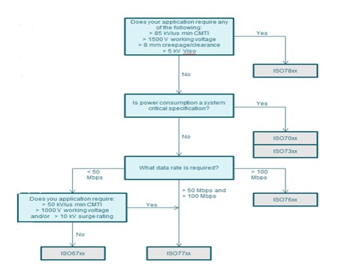
Figure 1: selection flowchart of the digital isolator
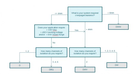
Figure 2: selection flowchart of packaging type
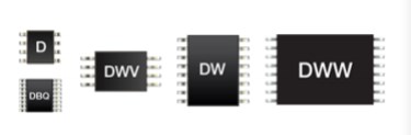
Figure 3: proportion of each package
 UTMEL
UTMEL
We are the professional distributor of electronic components, providing a large variety of products to save you a lot of time, effort, and cost with our efficient self-customized service. careful order preparation fast delivery service
1.How do digital isolation devices work?
To do this, digital isolation devices use semiconductor process technology to create either transformers or capacitors to transfer data instead of light. With this technology, performance and feature integration are both improved.
2. What is the difference between an optocoupler and a digital isolator?
A digital isolator's goal is to meet safety requirements while minimizing incurred penalties. Optocouplers, a traditional isolator, incur the greatest penalties, consuming high levels of power and limiting data rates to below 1 Mbps. More power-efficient and higher speed optocouplers are available but impose a higher cost penalty.
3. What does a digital isolator do?
Digital isolators are integrated devices used to isolate digital signals and transfer digital communication across an isolation barrier. The input signal is modulated through a transmit IC and then passed through a high voltage capacitive barrier and across the connecting bond wire to the receiving side IC.
4. What is an analog isolator?
Analog Devices' digital isolators enable designers to implement robust solutions with our magnetically isolated Coupler products with the flexibility of up to 6 channels. Products meet stringent safety standards including the ability to isolate IS-IS with our intrinsically safe certified digital isolators which enable designs in hazardous areas.
5. Which is digital isolators provide ultra-low power isolation?
The ISO70xx family of digital isolators provides ultra-low-power isolation with our robust capacitive SiO2 insulation barrier.
 What is a Great Choice for Digital Isolators to Build Isolation Barriers?UTMEL31 March 20225243
Hello everyone, I am Rose. Welcome to the new post today. A digital isolator is a chip that has high resistance isolation characteristics when digital signals and analog signals are transmitted in an electronic system to realize the isolation between the electronic system and the user. and capacitive isolation to achieve.
Read More How to Select a Digital Isolator?UTMEL12 April 20217136
A digital isolator is a chip used to make the electronic system have high resistance isolation when signals and analog signals are transmitted, so as to realize the isolation between the electronic system and its users. The reason why designers introduce isolation is to meet safety regulations or reduce ground loop noise.
Read More Vibration Isolator: Types and ApplicationsUTMEL13 January 202112697
A vibration isolator is an elastic element connecting equipment and foundation to reduce and eliminate the vibration force transmitted from the equipment to the foundation and the vibration transmitted from the foundation to the equipment. This article will introduce some of the types of vibration isolators and their applications to you.
Read More What is An Optoisolator?UTMEL09 January 20218403
An optoisolator, also called optical coupler, optocoupler, and opto-isolator, is a device that encapsulates the infrared light-emitting device, the infrared light receiving device, and the signal processing circuit in the same tube socket.
Read More
Subscribe to Utmel !
