Product
 Brand
Brand Articles
 Tools
Tools
Introduction to Acceleration Sensors
Working principle of an acceleration sensor
📅 Last Updated: November 2025
Note: This article has been updated to reflect the latest developments in acceleration sensor technology, including MEMS advancements, AI integration, and emerging applications in IoT and autonomous systems.
📑 Table of Contents
II. Classification of Acceleration Sensors
6. Resistance/Impedance Considerations
IV. Applications of Acceleration Sensors
4. Electronic Compass Tilt Correction
10. Device Orientation Detection
V. Installation Considerations
VI. Future Trends (2025 and Beyond)
I. Working Principle
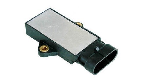
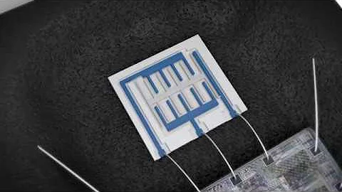
Figure 1. Acceleration Sensors
Acceleration sensors, also known as accelerometers, are devices that measure acceleration forces. These forces may be static (like gravity) or dynamic (caused by moving or vibrating the sensor). The fundamental principle of linear acceleration sensors is based on Newton's second law of motion:
A (acceleration) = F (inertial force) / M (mass)
By measuring the inertial force acting on a known mass, we can calculate the acceleration. Modern acceleration sensors typically use electromagnetic force to balance the inertial force, establishing a relationship between force and electrical current or voltage output.
Most acceleration sensors operate based on the piezoelectric effect. This phenomenon occurs when mechanical stress is applied to certain crystalline materials, causing them to generate an electrical charge. As defined: "When external force is applied to a heteropolar crystal without a symmetric center, the crystal not only deforms but also changes its polarization state, establishing an electric field within the crystal. This polarization phenomenon caused by mechanical force is called the direct piezoelectric effect."
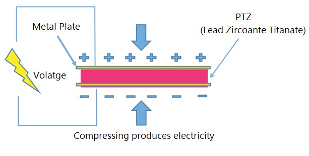
Figure 2. Piezoelectric Effect
General acceleration sensors utilize the characteristic of crystal deformation caused by internal acceleration. This deformation generates a voltage proportional to the applied acceleration. By calibrating the relationship between voltage and acceleration, the sensor converts physical acceleration into an electrical signal.
While piezoelectric technology is common, other methods exist for creating acceleration sensors, including:
Piezoresistive technology - measures resistance changes under stress
Capacitive effect - detects capacitance changes due to displacement
Thermal (bubble) effect - measures heat transfer changes
Optical methods - uses light interference patterns
Each technology has unique advantages and limitations. The most basic principle remains consistent: a medium deforms due to acceleration, and this deformation is converted into a measurable electrical signal.
II. Classification of Acceleration Sensors
1. Piezoelectric Accelerometers
Piezoelectric acceleration sensors, also called piezoelectric accelerometers, belong to the category of inertial sensors. They utilize the piezoelectric properties of materials such as piezoelectric ceramics or quartz crystals. When the sensor experiences vibration, the force applied to the piezoelectric element by the seismic mass changes accordingly.
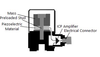
Figure 3. Cross-section of a Piezoelectric Accelerometer
When the measured vibration frequency is significantly lower than the sensor's natural frequency, the force change is proportional to the measured acceleration. These sensors are particularly effective for dynamic measurements and high-frequency vibration analysis.
Advantages:
Wide frequency range (typically 1 Hz to 10 kHz or higher)
High sensitivity
Excellent linearity
Self-generating (no external power needed for basic operation)
Robust and reliable
Limitations:
Cannot measure true DC (static) acceleration
Requires charge amplifier or voltage amplifier
Temperature sensitivity
2. Piezoresistive Accelerometers
Piezoresistive acceleration sensors leverage advanced MEMS (Micro-Electro-Mechanical Systems) silicon micromachining technology. These sensors offer several key advantages:
Extremely small size (often less than 5mm)
Very low power consumption (microampere range)
Easy integration with analog and digital circuits
Can measure from DC (0 Hz) to several kHz
Cost-effective for mass production
These sensors are widely used in automotive crash testing, equipment vibration monitoring, structural health monitoring, and consumer electronics. The piezoresistive effect causes resistance changes in semiconductor materials when subjected to mechanical stress, which can be measured using a Wheatstone bridge configuration.
3. Capacitive Accelerometers
Capacitive acceleration sensors operate based on changes in capacitance. They typically consist of fixed plates and a movable proof mass. When acceleration occurs, the proof mass moves, changing the gap between capacitor plates and thus altering the capacitance.
These sensors have become dominant in many applications, particularly:
Automotive airbag systems
Smartphones and tablets
Wearable devices
Gaming controllers
Industrial equipment monitoring
Key advantages:
Excellent DC response (can measure static acceleration)
Low power consumption
High sensitivity
Good temperature stability
Cost-effective with MEMS technology
Can be manufactured in very small sizes
Modern capacitive MEMS accelerometers often include built-in signal conditioning, digital interfaces (I²C, SPI), and programmable features, making them highly versatile for various applications.
4. Servo Accelerometers
Servo acceleration sensors represent a closed-loop measurement system with excellent dynamic performance, large dynamic range, and superior linearity. These are precision instruments used in demanding applications.

Figure 4. Servo Type Accelerometer
The vibration system follows the "m-k" (mass-spring) model, similar to other accelerometers, but includes an electromagnetic coil on the proof mass. When acceleration is applied:
The proof mass begins to deviate from its equilibrium position
A displacement sensor detects this movement
A servo amplifier processes the signal and converts it to current
This current flows through an electromagnetic coil
The coil generates a restoring force in a permanent magnetic field
This force attempts to maintain the mass at its original equilibrium position
Because of this feedback mechanism, servo accelerometers offer:
Enhanced anti-interference capability
Improved measurement accuracy (often better than 0.01% of full scale)
Extended measurement range
Excellent frequency response
These sensors are widely used in:
Inertial navigation systems
Inertial guidance systems
High-precision vibration measurement
Calibration standards
Aerospace applications
Seismic monitoring
III. Technical Parameters
1. Output Mode
The output type is a critical consideration that depends on your system's interface requirements. Modern acceleration sensors offer various output options:
Analog Output:
Voltage output: Typically proportional to acceleration (e.g., 2.5V = 0g, 2.6V = 0.5g)
Current output: 4-20mA signals for industrial applications
Charge output: From piezoelectric sensors, requires charge amplifier
Digital Output:
PWM (Pulse Width Modulation): Duty cycle proportional to acceleration
I²C: Popular two-wire serial interface
SPI: High-speed serial peripheral interface
UART: Universal asynchronous serial communication
CAN bus: For automotive and industrial applications
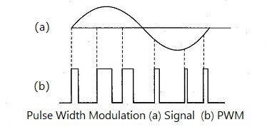
Figure 5. Pulse Width Modulation (PWM)
For microcontrollers with only digital inputs (like some basic development boards), digital output sensors are necessary. However, they require additional processing overhead to decode the signal.
For microcontrollers with analog-to-digital converters (ADC), such as modern ARM, PIC, AVR, or ESP32 platforms, analog sensors can be simpler to implement. A simple ADC read command can acquire the acceleration value in microseconds.
2025 Update: Most modern sensors now include digital interfaces with built-in ADC, signal processing, and even AI-capable features for edge computing applications.
2. Number of Measuring Axes
Acceleration sensors are available in different axis configurations:
Single-axis: Measures acceleration along one direction
Dual-axis (2D): Measures in two perpendicular directions (X and Y)
Triple-axis (3D): Measures in all three spatial dimensions (X, Y, and Z)
For most applications, a three-axis accelerometer is now the standard choice due to:
Complete motion detection capability
Ability to measure tilt in any orientation
Minimal cost difference compared to 2-axis versions
Single package simplicity
Three-axis sensors are essential for:
Drones and UAVs (Unmanned Aerial Vehicles)
Robotics and ROVs (Remotely Operated Vehicles)
Smartphones and tablets
Virtual reality (VR) and augmented reality (AR) devices
Wearable fitness trackers
Advanced driver assistance systems (ADAS)
3. Maximum Measured Value (Measurement Range)
The measurement range, typically expressed in "g" (where 1g = 9.81 m/s²), should be selected based on your application:
±1.5g to ±2g: Suitable for tilt sensing, orientation detection, and low-impact applications
±4g to ±8g: General-purpose motion detection, gaming, and consumer electronics
±16g to ±50g: High-impact applications, sports analytics, crash detection
±100g to ±500g: Automotive crash testing, military applications
±1000g and above: Ballistics, explosive testing, extreme impact events
Consider these guidelines:
For measuring robot inclination relative to ground: ±2g is sufficient
For dynamic robot performance: ±4g to ±8g recommended
For sudden starts/stops or impact detection: ±16g or higher
For vehicle airbag systems: ±50g to ±100g typical
Important: Higher range sensors generally have lower resolution. Choose the smallest range that accommodates your maximum expected acceleration for best resolution.
4. Sensitivity
Sensitivity indicates how much the output changes per unit of acceleration. It's typically expressed as:
mV/g for analog voltage output sensors
pC/g (picocoulombs per g) for charge output sensors
LSB/g (least significant bits per g) for digital sensors
Higher sensitivity generally provides:
Better resolution for small acceleration changes
Improved signal-to-noise ratio (SNR)
More accurate measurements at low acceleration levels
However, sensitivity must be balanced with measurement range. The relationship is typically inverse: higher sensitivity means lower maximum range.
Calculation considerations:
Maximum Output = Maximum Acceleration × Sensor Sensitivity
Ensure this value doesn't exceed your measurement system's input limits. For optimal performance, select sensitivity that provides good signal strength while maintaining adequate headroom for your maximum expected acceleration.
5. Bandwidth (Frequency Response)
Bandwidth refers to the range of frequencies the sensor can accurately measure. It's often confused with sample rate but represents different characteristics:
Bandwidth specifications:
DC to 50 Hz: Tilt sensing, orientation, slow motion
DC to 100-500 Hz: Human motion, gesture recognition, general robotics
DC to 1-5 kHz: Vibration analysis, machinery monitoring
1 Hz to 10 kHz+: High-frequency vibration, acoustic analysis
For different applications:
Tilt measurement: 50 Hz bandwidth sufficient
Gaming and motion control: 100-200 Hz adequate
Vibration monitoring: 500 Hz to several kHz required
Impact detection: 1 kHz or higher recommended
Structural health monitoring: Application-specific, often 1-5 kHz
2025 Update: Modern MEMS accelerometers commonly offer bandwidths up to 8 kHz with sample rates exceeding 32 kHz, enabling advanced vibration analysis and predictive maintenance applications.
6. Resistance/Impedance Considerations
Output impedance is crucial for proper interface with your measurement system:
For analog sensors:
Some microcontrollers require source impedance below 10kΩ for accurate ADC readings
High-impedance sensors (>32kΩ) may not work properly with certain MCUs
Buffer amplifiers can solve impedance matching issues
For piezoelectric sensors:
Very high output impedance (megohms to gigohms)
Require charge amplifiers or high-impedance voltage amplifiers
Cable capacitance affects sensitivity
Best practices:
Check your microcontroller's ADC input impedance requirements
Use appropriate signal conditioning if needed
Keep cable lengths short for high-impedance sensors
Consider sensors with built-in amplifiers for easier integration
Modern solution: Most current MEMS accelerometers include integrated signal conditioning with low-impedance outputs (typically<100Ω), eliminating impedance matching concerns.
7. Cumulative Error and Drift
When using accelerometers for position tracking through integration, several error sources accumulate:
Integration process:
Measure acceleration at time interval Δt
Integrate once to get velocity: v = v₀ + a×Δt
Integrate again to get position: s = s₀ + v×Δt
Error sources:
Bias error: Constant offset in acceleration reading
Noise: Random fluctuations in measurement
Temperature drift: Sensitivity changes with temperature
Quantization error: Limited resolution of ADC
Sampling rate limitations: Missing rapid changes
Error accumulation:
Velocity error grows linearly with time
Position error grows quadratically with time
After just 1 minute, position errors can exceed meters
Mitigation strategies:
Use complementary sensors (gyroscopes, magnetometers, GPS)
Implement Kalman filtering or sensor fusion algorithms
Periodic recalibration or zero-velocity updates
Higher sampling rates reduce integration error
Temperature compensation
2025 Update: Modern IMUs (Inertial Measurement Units) combine accelerometers with gyroscopes and often magnetometers, using advanced sensor fusion algorithms and AI-based calibration to significantly reduce drift. Some units now include on-chip machine learning for improved accuracy.
IV. Applications of Acceleration Sensors
1. Vehicle Safety Systems
Acceleration sensors play a critical role in automotive safety, with applications including:
Airbag deployment systems:
Detect sudden deceleration during collision
Typical response time:<2 milliseconds
Multiple sensors determine crash severity and direction
Modern vehicles use 10-20 accelerometers
Anti-lock Braking Systems (ABS):
Monitor wheel deceleration
Prevent wheel lockup during braking
Improve vehicle control and reduce stopping distance
Electronic Stability Control (ESC):
Detect lateral acceleration during turns
Prevent skidding and rollover
Automatically apply individual brakes to maintain control
Advanced Driver Assistance Systems (ADAS):
Adaptive cruise control
Lane departure warning
Collision avoidance systems
Automatic emergency braking

Figure 6. Acceleration Sensors in Modern Automobiles
2025 Update: Autonomous vehicles now use arrays of high-precision accelerometers combined with IMUs for precise motion control, requiring accuracy better than 0.1% and update rates exceeding 1 kHz.
2. Game Control and Motion Sensing
Acceleration sensors revolutionized gaming by enabling intuitive motion-based controls:
Console gaming: Controllers detect tilting, rotation, and gestures
Mobile gaming: Smartphone accelerometers enable steering and aiming
VR/AR gaming: Head tracking and motion capture for immersive experiences
Fitness gaming: Activity tracking and movement recognition
By detecting changes in tilt angle, players can control game objects by tilting handheld devices forward, backward, or side-to-side, creating more engaging and interactive gaming experiences.
3. Automatic Screen Rotation
One of the most common applications in consumer electronics, acceleration sensors enable:
Automatic portrait/landscape orientation switching
Detection of device rotation and direction
Seamless user experience across different viewing angles
Power-efficient implementation (low-power mode for continuous monitoring)
The sensor detects the device's orientation relative to gravity and triggers the display to rotate the image to match the correct viewing orientation.
4. Electronic Compass Tilt Correction
Magnetic sensors (magnetometers) determine direction by measuring magnetic flux. However, when tilted, the measured geomagnetic flux changes, causing directional errors.
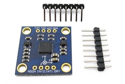
Figure 7. Electronic Compass with Acceleration Sensor Module
Acceleration sensors solve this problem by:
Measuring the tilt angle in real-time
Providing compensation data to the magnetometer
Enabling accurate compass readings regardless of device orientation
Supporting 3D compass functionality
This combination creates a tilt-compensated electronic compass that works accurately even when not held perfectly horizontal, essential for navigation applications.
5. GPS Navigation System Enhancement
GPS systems determine position by receiving signals from satellites. However, GPS has limitations in certain environments:
GPS dead zones:
Tunnels and underground passages
Urban canyons (between tall buildings)
Dense forests
Indoor environments
Parking garages
Acceleration sensors provide dead reckoning capability:
Continue tracking movement when GPS signal is lost
Integrate acceleration to estimate velocity changes
Combine with gyroscopes for direction information
Provide seamless navigation through dead zones
This integration of GPS and inertial navigation creates more reliable positioning systems, particularly important for:
Automotive navigation
Delivery and logistics tracking
Emergency services
Autonomous vehicles
6. Fitness Tracking and Pedometer Function
Acceleration sensors detect the AC (alternating) signal and vibration patterns created by human movement:
Step counting:
Detect regular vibration patterns during walking/running
Identify zero-crossing points in acceleration waveform
Count steps with high accuracy (typically >95%)
Distinguish between walking, running, and other activities

Figure 8. Pedometer with Built-in 3D Acceleration Sensor
Advanced fitness metrics:
Distance calculation using step length and count
Calorie expenditure estimation
Activity type recognition (walking, running, cycling, swimming)
Sleep quality monitoring
Fall detection for elderly care
2025 Update: Modern fitness trackers use machine learning algorithms with accelerometer data to provide highly accurate activity classification, energy expenditure calculations, and even detect specific exercises like push-ups, squats, or weightlifting movements.
7. Image Stabilization
Acceleration sensors enable both optical and digital image stabilization:
Camera shake detection:
Measure vibration and shake amplitude in real-time
Detect hand tremor frequencies (typically 1-12 Hz)
Provide feedback to stabilization systems
Stabilization methods:
Optical Image Stabilization (OIS): Physically move lens elements or sensor
Electronic Image Stabilization (EIS): Crop and shift digital image
Hybrid systems: Combine both methods for superior results
When excessive vibration is detected, the system can:
Lock the camera shutter until motion stabilizes
Adjust lens position to compensate for movement
Apply digital correction to captured images
Increase shutter speed to freeze motion
This ensures clear, sharp images even when shooting handheld or in challenging conditions.
8. Gesture Recognition
Modern gesture recognition systems use acceleration sensors to detect and interpret user movements:
Applications include:
Shake to activate: Wake device or trigger functions
Tap detection: Double-tap to activate screen or features
Rotation gestures: Flip to mute or switch modes
Gesture commands: Draw patterns in air for control
Wrist gestures: Control smartwatches without touching screen
The acceleration sensor detects motion patterns and, using signal processing or machine learning algorithms, interprets them as specific commands. This enables intuitive, hands-free interaction with devices.
2025 Update: AI-powered gesture recognition now enables complex motion patterns, sign language interpretation, and personalized gesture customization using on-device machine learning.
9. Hard Disk Protection
Although less common with the rise of solid-state drives (SSDs), acceleration sensors still protect traditional hard disk drives (HDDs):
Free-fall detection:
Detect when device enters free-fall state (all axes read ~0g)
Typical detection time: 5-20 milliseconds
Trigger protective measures before impact
Protection mechanisms:
Park read/write heads in safe zone
Stop disk rotation
Lock head assembly
Prevent data loss and physical damage
During normal operation, the magnetic head flies just nanometers above the spinning disk. Even slight vibrations can cause head crashes and data loss. The acceleration sensor provides early warning of potentially damaging events.
2025 Note: While HDDs are being replaced by SSDs in many applications, they remain common in data centers and high-capacity storage systems where this protection is still valuable.
10. Device Orientation and Pose Detection
Acceleration sensors, often combined with gyroscopes and magnetometers in an Inertial Measurement Unit (IMU), enable comprehensive pose detection:

Figure 9. Motion-Sensing Applications
Sensor fusion benefits:
Accelerometer: Measures tilt using gravity, affected by motion
Gyroscope: Measures rotation rate, drifts over time
Magnetometer: Measures heading, affected by magnetic interference
Combined: Each sensor compensates for others' weaknesses
Applications:
Virtual reality headset tracking
Drone flight stabilization
Robot navigation and balance
Augmented reality positioning
Motion capture for animation
Sports performance analysis
Modern sensor fusion algorithms (Kalman filters, complementary filters, or AI-based methods) combine data from multiple sensors to provide accurate, drift-free orientation information.
11. Smart Wearables and IoT Applications
Acceleration sensors are fundamental to the rapidly growing wearable and IoT markets:
Smartwatches and fitness bands:
Activity tracking and classification
Heart rate measurement assistance
Sleep stage detection
Gesture control
Fall detection and emergency alerts
Healthcare applications:
Parkinson's disease tremor monitoring
Gait analysis for rehabilitation
Seizure detection
Elderly fall prevention
Post-surgery recovery tracking
Industrial IoT:
Predictive maintenance through vibration analysis
Equipment health monitoring
Structural integrity assessment
Transportation and logistics tracking
Asset management
Smart home applications:
Door/window open detection
Appliance usage monitoring
Security systems
Energy management

Figure 10. Three-Axis Acceleration Measurement in Smart Devices
2025 Update: The integration of AI at the edge has transformed accelerometer applications. Modern sensors include on-chip neural networks that can classify activities, detect anomalies, and make decisions locally without cloud connectivity, enabling:
Real-time health monitoring with medical-grade accuracy
Predictive maintenance with failure prediction weeks in advance
Personalized fitness coaching with form correction
Enhanced privacy through local processing
Reduced power consumption and latency
V. Installation Considerations
Proper installation is crucial for accurate acceleration measurements. The mounting method significantly affects the sensor's frequency response and measurement accuracy.
Key considerations:
Sensor weight relative to test structure
Frequency range of interest
Expected acceleration amplitude
Temperature range during testing
Environmental conditions (vibration, shock, humidity)
Mounting surface characteristics
Mounting Methods and Adhesives
The choice of adhesive directly impacts the sensor's natural frequency and coupling efficiency:
1. Stud mounting (permanent):
Best frequency response (up to sensor's full bandwidth)
Most rigid coupling
Requires threaded hole in test surface
Ideal for: High-frequency measurements, permanent installations
2. Adhesive mounting:
Cyanoacrylate (super glue):
Excellent frequency response (typically >10 kHz)
Fast curing (seconds to minutes)
Good for temporary installations
Temperature range: -50°C to +100°C
Removal: Acetone or heat

Figure 11. Cyanoacrylate Adhesives for Sensor Mounting
Epoxy adhesives:
Very strong, permanent bond
Excellent frequency response
Longer curing time (hours)
Temperature range: -50°C to +150°C
Difficult to remove
Hot glue:
Moderate frequency response (typically<5 kHz)
Easy application and removal
Good for temporary testing
Limited temperature range
3. Magnetic mounting:
Quick attachment/removal
Good frequency response on ferromagnetic surfaces
Limited to flat, smooth surfaces
Frequency response: typically up to 2-7 kHz
Ideal for: Quick surveys, multiple test points
4. Wax mounting:
Temporary mounting for light sensors
Easy removal with heat
Limited frequency response (<2 kHz)
Temperature sensitive
Good for: Quick tests, delicate surfaces
5. Double-sided tape:
Quick and clean installation
Moderate frequency response (<3 kHz)
Easy removal
Suitable for low-frequency measurements
Installation Best Practices
Surface preparation:
Clean mounting surface with hydrocarbon solvent (isopropyl alcohol, acetone)
Remove oil, grease, paint, or rust
Ensure surface is dry before applying adhesive
For best results, lightly sand or grind surface flat
Adhesive application:
Use minimal amount of adhesive
Apply thin, uniform layer
Avoid thick adhesive layers (reduces frequency response)
Ensure no air bubbles trapped
Apply firm pressure during curing
Important guidelines:
Sensor weight should be<10% of test structure mass (ideally <1%)
Mount sensor close to point of interest
Ensure mounting surface is rigid (not flexible)
Align sensor axes with desired measurement directions
Protect cables from vibration (strain relief)
Avoid mounting near heat sources if possible
Allow adequate curing time before testing
Temperature considerations:
Don't apply adhesive near maximum temperature limits
Allow adhesive to cure at room temperature when possible
High temperatures reduce adhesive strength
Consider thermal expansion differences
Use high-temperature adhesives for hot environments
Verification:
Tap test to verify good coupling
Check for resonances in frequency response
Compare with reference measurements if possible
Monitor for changes over time
2025 Update: Modern MEMS accelerometers often come in surface-mount packages designed for PCB integration, eliminating many traditional mounting concerns. For these devices, proper PCB design (rigid mounting, adequate ground planes, vibration isolation from other components) becomes the critical factor.
VI. Future Trends (2025 and Beyond)
The acceleration sensor industry continues to evolve rapidly with several emerging trends:
1. AI Integration and Edge Computing:
On-chip neural networks for real-time pattern recognition
Self-calibration and adaptive filtering
Predictive maintenance with AI-powered anomaly detection
Personalized health monitoring algorithms
Energy-efficient inference at the sensor level
2. Ultra-Low Power Operation:
Nano-watt power consumption in sleep modes
Energy harvesting integration
Always-on context awareness
Multi-year battery life for IoT devices
3. Enhanced Performance:
Noise levels below 10 µg/√Hz
Bias stability better than 1 mg over temperature
Wider bandwidth (DC to 10+ kHz in compact packages)
Higher shock survival (>10,000g)
Improved temperature stability
4. Miniaturization:
Package sizes below 1mm × 1mm
Integration with other sensors in single package
Flexible and stretchable sensor arrays
Implantable medical-grade sensors
5. Advanced Applications:
Autonomous vehicles: Sensor fusion for precise motion control
Healthcare: Continuous health monitoring and early disease detection
Industry 4.0: Predictive maintenance and digital twins
Smart cities: Infrastructure health monitoring
Space exploration: Navigation and scientific measurements
Quantum sensing: Ultra-precise measurements for research
6. Connectivity and Standards:
Wireless sensor networks with mesh capability
5G and IoT protocol integration
Standardized interfaces (IO-Link, OPC UA)
Cloud connectivity with edge processing
Blockchain for sensor data integrity
7. Environmental Considerations:
Lead-free and RoHS compliant manufacturing
Recyclable materials and sustainable production
Reduced environmental impact
Longer product lifecycles
8. Security:
Hardware-based encryption
Secure boot and firmware updates
Authentication mechanisms
Protection against tampering and spoofing
📚 Recommended Articles:
What are Weight Sensors? 50 World Famous Sensor Manufacturing Companies Types and Application of Position Sensors What is an Oxygen Sensor?
📝 Article Update Information:
Original Publication: 2020
Last Updated: November 2025
Major Updates:
Added section on AI integration and edge computing capabilities
Updated technical specifications to reflect 2025 state-of-the-art
Expanded applications section with modern use cases
Added future trends section covering emerging technologies
Corrected terminology (e.g., "cache mechanism" to "impedance considerations")
Updated information on autonomous vehicles and IoT applications
Enhanced mobile-responsive formatting with improved styling
Added context about SSD replacing HDD in many applications
Updated sensor fusion and machine learning applications
Next Review: Scheduled for Q4 2026
This article provides general information about acceleration sensors. For specific applications, always consult manufacturer datasheets and application notes.
 UTMEL
UTMEL
We are the professional distributor of electronic components, providing a large variety of products to save you a lot of time, effort, and cost with our efficient self-customized service. careful order preparation fast delivery service
1.How does acceleration sensor work?
An accelerometer is a device that measures the vibration, or acceleration of motion of a structure. The force caused by vibration or a change in motion (acceleration) causes the mass to "squeeze" the piezoelectric material which produces an electrical charge that is proportional to the force exerted upon it.
2.Where are accelerometers used?
Accelerometers can be used to measure vibration on cars, machines, buildings, process control systems, and safety installations. They can also be used to measure seismic activity, inclination, machine vibration, dynamic distance, and speed with or without the influence of gravity.
3.What is the function of accelerometer sensor in mobile phones?
Accelerometers in mobile phones are used to detect the orientation of the phone. The gyroscope, or gyro for short, adds an additional dimension to the information supplied by the accelerometer by tracking rotation or twist.
4.What is the working principle of accelerometer?
The basic underlying working principle of an accelerometer is such as a dumped mass on a spring. When acceleration is experienced by this device, the mass gets displaced till the spring can easily move the mass, with the same rate equal to the acceleration it sensed.
5.What is the difference between speed and acceleration?
Speed is the rate of change of distance(basically how much distance(m) has been covered in a particular time(s)). Velocity is the rate of change of displacement( change of distance in a particular direction with respect to time), and acceleration is the rate of change of velocity per unit of time.
 The Key Role of Electronic Components in IoT DevicesUTMEL01 September 20235758
The article discusses the pivotal role of electronic components in Internet of Things (IoT) devices. IoT devices work by capturing real-world data using sensors, processing it through a microcontroller, and then sending it to the cloud for further analysis.
Read More How to Identify the Perfect Proximity Sensor for Your ApplicationUTMEL19 July 20251670
Find the best proximity sensors for your project by evaluating material, sensing range, environment, and system needs to ensure optimal performance and reliability.
Read More Trusted Vibration Sensors for Homeowners and Industry ProfessionalsUTMEL17 July 20251317
Compare top vibration sensors for home and industrial use. Find trusted options for security, predictive maintenance, and equipment protection.
Read More Wiring and Mounting Photoelectric Sensors in 2025UTMEL15 July 20251521
Wire and mount photoelectric sensors in 2025 with step-by-step safety, wiring, and alignment tips for reliable installation and optimal sensor performance.
Read More Essential Tips for Picking the Best Gas SensorUTMEL15 July 20252886
Find out how to select gas sensors by matching target gases, environment, and compliance needs for reliable and accurate gas detection in any setting.
Read More
Subscribe to Utmel !