Product
 Brand
Brand Articles
 Tools
Tools
What is a Vibration Sensor?
What is a Vibration Sensor?
Catalog
Ⅱ Working Principle of Vibration Sensors | ||
3.1 Piezoelectric Acceleration Sensor | ||
3.2 Piezoelectric Force Sensor | ||
3.3 Impedance Head | ||
8.1 Phase-modulated Fiber Optic Vibration Sensor | ||
8.2 Optical Stress System Fiber Optic Vibration Sensor | ||
8.3 Wavelength Modulated Optical Fiber Vibration Sensor | ||
10 Wireless and IoT-Enabled Vibration Sensors (2025 Addition) | ||
Ⅰ Introduction
Vibration is one of the most common phenomena in nature, existing in everything from the universe to atomic particles. Vibration is ubiquitous in the field of engineering technology, but in many cases, vibration can be harmful. Vibration reduces machining precision and surface finish, and accelerates the wear of structural components. In the automotive and aviation industries, vibration of the airframe and structural parts not only affects operator performance but can also cause fracture and disintegration of critical components.
A vibration sensor is used to detect the impact force or acceleration of mechanical systems. Modern vibration sensors typically utilize piezoelectric devices, MEMS technology, or other transduction principles that generate electrical signals proportional to mechanical vibration. These sensors can perform long-term monitoring of vibration, displacement, thermal expansion of rotors, and chassis movement. They are essential for online automatic detection and control in production lines and various measurements of minute distances and motions in scientific research.
2025 Update: Modern vibration sensors now incorporate advanced features such as wireless connectivity, IoT integration, machine learning algorithms for predictive maintenance, and enhanced sensitivity through nanotechnology improvements.
Vibration sensors are widely used across numerous industries including energy, chemical processing, medicine, automotive, metallurgy, manufacturing, defense, aerospace, scientific research, and education.
Ⅱ Working Principle of Vibration Sensors
There are several methods for vibration sensors to measure vibration, but the following three fundamental principles are most commonly adopted:
Mechanical Measurement: Engineering vibration is converted into mechanical signals, then amplified by mechanical systems before measurement and recording. Common instruments include lever-type vibrometers and Geiger vibrometers. This method has relatively low measurement frequency and accuracy but offers convenient operation.
Optical Measurement: Variations in engineering vibration are converted into optical signals, which are amplified by optical systems and then displayed and recorded. Laser vibrometers and interferometric systems utilize this principle, offering non-contact measurement capabilities.
Electrical Measurement: Variations in engineering vibration are converted into electrical signals, which are amplified, processed, and recorded. This method first converts mechanical vibration into electrical quantities, then measures them according to established relationships to determine vibration magnitude. This is currently the most widely used vibration measurement method due to its versatility and integration capabilities.
Modern Integration: Contemporary vibration measurement systems combine all three principles through sensor fusion, digital signal processing, and advanced algorithms to provide comprehensive vibration analysis.
Ⅲ Classification of Vibration Sensors
In terms of mechanical receiving principles, there are fundamentally two types of vibration sensors: relative type and inertial type. However, regarding electromechanical transformation, various transformation methods and properties result in numerous sensor types with extensive application ranges. Modern vibration sensors are no longer standalone mechanical measurement devices but integral components of comprehensive measurement systems closely integrated with electronic circuits.
Due to different electromechanical transformation principles, sensors produce different output signals. Some convert mechanical quantities into electromotive force and charge, while others convert mechanical vibration into changes in resistance, inductance, capacitance, or other parameters.
Generally, vibration sensors can be classified according to different criteria:
Mechanical Reception Principle: Relative type and inertial type
Electromechanical Transformation Principle: Electrodynamic, piezoelectric, eddy current, inductive, capacitive, resistive, photoelectric, and MEMS types
Measured Mechanical Quantity: Displacement sensors, velocity sensors, acceleration sensors
Output Signal Type: Analog and digital sensors
Communication Method: Wired and wireless sensors
1 Relative and Inertial Vibration Sensors
Relative vibration sensors primarily measure the motion of a vibrating body relative to its reference point, such as machine tool shaft vibration relative to the machine base.
Inertial vibration sensors measure the motion of a vibrating body relative to ground or inertial space, such as machine base vibration, ground vibration, or aircraft vibration in flight. These sensors contain an inertial mass block, hence the term "inertial vibration sensor."
Inertial vibration sensors must be installed in contact with the test object, while relative sensors can be either contact or non-contact types.
2 Electrodynamic Vibration Sensor
Electrodynamic vibration sensors are divided into relative and inertial types.
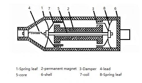
Magnetoelectric vibration sensor
Relative electrodynamic sensors operate on the principle of electromagnetic induction. When a moving conductor cuts through magnetic field lines in a fixed magnetic field, an electromotive force is generated across the conductor ends.
Inertial electrodynamic sensors consist of fixed parts, movable parts, and supporting spring components. For the sensor to function as a displacement sensor, the movable part must have sufficient mass, and the supporting spring must have low stiffness, resulting in a sufficiently low natural frequency.
According to electromagnetic induction law: U = BLẋ
Where: B = magnetic flux density, L = effective coil length in magnetic field, ẋ = relative velocity of coil in magnetic field
3 Piezoelectric Vibration Sensor
Piezoelectric vibration sensors include acceleration sensors, force sensors, and impedance heads.
3.1 Piezoelectric Acceleration Sensor
The mechanical receiving component operates on inertial acceleration principles, while the electromechanical component utilizes the direct piezoelectric effect of piezoelectric crystals. When certain crystals are deformed by external force, charges are generated on their surfaces. This conversion from mechanical to electrical energy is the direct piezoelectric effect.
Since the force on the piezoelectric crystal is the inertial force of the mass block, the generated charge is proportional to acceleration magnitude, making the piezoelectric sensor an acceleration sensor.
3.2 Piezoelectric Force Sensor
In vibration testing, measuring dynamic excitation forces applied to specimens is often necessary. Piezoelectric force sensors are widely used due to their wide frequency range, large dynamic range, compact size, and lightweight design. The output charge signal is proportional to external force.
3.3 Impedance Head
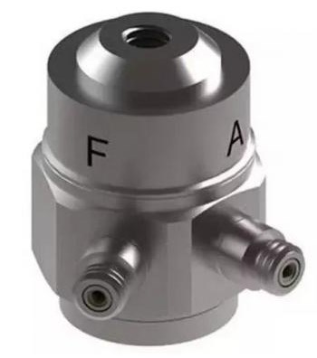
Impedance head
An impedance head is an integrated sensor combining a piezoelectric force sensor and acceleration sensor, designed to simultaneously measure vibration force and motion response at force transfer points.
4 Eddy Current Vibration Sensor

Eddy current vibration sensor
Eddy current vibration sensors are relative, non-contact sensors that measure vibration displacement or amplitude by detecting distance changes between the sensor tip and the measured object.
These sensors offer wide frequency range (0-10 kHz), large linear working range, high sensitivity, and non-contact measurement capabilities. They are primarily used for static displacement, vibration displacement, and shaft vibration monitoring in rotating machinery.
5 Inductive Vibration Sensor
Inductive vibration sensors operate on electromagnetic induction principles, equipped with magnets and magnetic bodies. They convert mechanical vibration parameters into electrical signals through two forms: variable air gap and variable magnetic permeability area. These sensors can measure vibration velocity, acceleration, and other parameters.
6 Capacitive Vibration Sensor

Capacitive vibration sensor
Capacitive vibration sensors obtain variable capacitance by changing the gap or common area between plates, then determine mechanical vibration parameters by measuring capacitance changes. They are divided into variable gap type (for linear vibration displacement) and variable common area type (for angular displacement in torsional vibration).
7 Resistance Strain Type Vibration Sensor
Resistance strain vibration sensors convert measured mechanical vibration into resistance changes in sensing elements. The most common sensing element is the resistance strain gauge.
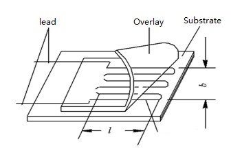
Resistance strain gauge
The basic structure includes a sensitive grid, base, leads, and cover plate. The sensitive grid is formed by fine wires (0.01-0.05mm diameter) with high resistance coefficient, serving as the strain-sensing element.
8 Fiber Optic Vibration Sensor
With advances in optical fiber and optoelectronic devices, fiber optic sensing technology has developed rapidly. These sensors offer advantages including small size, light weight, high precision, fast response, wide dynamic range, excellent electromagnetic interference resistance, corrosion resistance, and electrical isolation.
8.1 Phase-modulated Fiber Optic Vibration Sensor
Phase-modulated sensors utilize coherent laser sources and single-mode fibers. Light is separated and transmitted through fibers, and interference affecting one fiber causes detectable phase differences measured with interferometers (Mach-Zehnder, Michelson, Fabry-Perot, or Sagnac types).
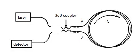
3dB coupler
8.2 Optical Stress System Fiber Optic Vibration Sensor
Based on mature fiber coupling technology, these all-fiber devices offer high performance with wide measurement bandwidth, high sensitivity, simple demodulation, low cost, and ease of use.
8.3 Wavelength Modulated Optical Fiber Vibration Sensor
The principle involves interaction between the measured field/parameter and sensitive fiber, causing wavelength changes in transmitted light. The measured parameter is determined by detecting wavelength variations.
Bragg's central wavelength: λB = 2neffΛ
Where: neff = effective refractive index of fiber core, Λ = grating period
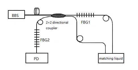
Fiber Bragg grating vibration sensor (1)

Fiber Bragg grating vibration sensor (2)
9 MEMS Vibration Sensors (2025 Addition)
New Technology Spotlight: MEMS (Micro-Electro-Mechanical Systems) vibration sensors have become increasingly important since 2020.
MEMS vibration sensors represent a significant advancement in sensor technology, offering:
Ultra-compact size: Typically less than 5mm in any dimension
Low power consumption: Ideal for battery-powered applications
High integration: Can include built-in signal processing and digital interfaces
Cost-effective mass production: Semiconductor manufacturing processes
Multi-axis sensing: Single chip can measure vibration in multiple directions
Modern MEMS accelerometers use capacitive, piezoresistive, or piezoelectric sensing principles and are widely used in consumer electronics, automotive safety systems, industrial monitoring, and IoT applications.
10 Wireless and IoT-Enabled Vibration Sensors (2025 Addition)
Industry 4.0 Integration: Wireless vibration sensors with IoT capabilities have revolutionized predictive maintenance and remote monitoring.
Modern wireless vibration sensors incorporate:
Wireless Communication: Wi-Fi, Bluetooth, LoRaWAN, 5G, and other protocols
Edge Computing: On-board processing for real-time analysis
Machine Learning: AI algorithms for pattern recognition and anomaly detection
Energy Harvesting: Self-powered operation using vibration energy
Cloud Integration: Seamless data upload and remote monitoring
Predictive Maintenance: Advanced algorithms predict equipment failures
These sensors enable Industry 4.0 applications including smart factories, condition monitoring systems, and autonomous maintenance scheduling.
Market Trends (2025): The global vibration sensor market is expected to reach $3.2 billion by 2025, driven by increasing adoption in automotive, aerospace, and industrial automation sectors.
Related Articles:
Introduction to the Types of IoT Sensors
Function and Application of Laser Sensors
MEMS Sensors in Industrial Applications (2025)
Wireless Sensor Networks for Predictive Maintenance (2025)
Article Update Information:
Original Publication: 2020
Last Updated: October 2025
Major Updates: Added MEMS sensors section, wireless/IoT capabilities, corrected technical specifications, updated market information, improved formatting and readability, added 2025 technology trends and applications.
 UTMEL
UTMEL
We are the professional distributor of electronic components, providing a large variety of products to save you a lot of time, effort, and cost with our efficient self-customized service. careful order preparation fast delivery service
What is vibration sensor?
A vibration sensor is a device that measures the amount and frequency of vibration in a given system, machine, or piece of equipment. Those measurements can be used to detect imbalances or other issues in the asset and predict future breakdowns.
How do I choose a vibration sensor for my motor?
As a rule of thumb, if the machine produces high amplitude vibrations (greater than 10 g rms) at the measurement point, a low sensitivity (10 mV/g) sensor is preferable. If the vibration is less than 10 g rms, a 100 mV/g sensor should generally be used.
Which type of sensor is activated by vibration?
A piezoelectric vibration sensor (also known as piezo sensors) use the effect of mechanical strain caused by high-frequency motion of the equipment to detect acceleration and, hence, vibration.
What is the range of vibration sensor?
In a standard application (50g range), the sensitivity of a typical vibration sensor is 100mV/g, while in low vibration applications (10g) the sensitivity is 500mV/G. Vibration frequency – Knowing the frequency span you need to measure is as important as knowing the vibration range.
What is the principle of vibration sensor?
The vibration sensor is also called a piezoelectric sensor. This sensor uses the piezoelectric effects while measuring the changes within acceleration, pressure, temperature, force otherwise strain by changing to an electrical charge.
 The Key Role of Electronic Components in IoT DevicesUTMEL01 September 20235798
The article discusses the pivotal role of electronic components in Internet of Things (IoT) devices. IoT devices work by capturing real-world data using sensors, processing it through a microcontroller, and then sending it to the cloud for further analysis.
Read More Accelerometer Sensors Guide: Working Principle, Circuit Design, Specifications, and ApplicationsUTMEL25 June 2026191
A practical accelerometer sensor guide covering working principles, MEMS and piezoelectric types, datasheet specifications, circuit design, mounting, applications, and selection.
Read More How to Identify the Perfect Proximity Sensor for Your ApplicationUTMEL19 July 20251707
Find the best proximity sensors for your project by evaluating material, sensing range, environment, and system needs to ensure optimal performance and reliability.
Read More Trusted Vibration Sensors for Homeowners and Industry ProfessionalsUTMEL17 July 20251357
Compare top vibration sensors for home and industrial use. Find trusted options for security, predictive maintenance, and equipment protection.
Read More Wiring and Mounting Photoelectric Sensors in 2025UTMEL15 July 20251553
Wire and mount photoelectric sensors in 2025 with step-by-step safety, wiring, and alignment tips for reliable installation and optimal sensor performance.
Read More
Subscribe to Utmel !