Product
 Brand
Brand Articles
 Tools
Tools
Strain Gauges: Structure, Working Principle and Common Types

Strain Gauge 101 - Learn the basics of how they're used
Catalog
| I. Structure | 1. Sensitive Grid |
| 2. Substrate | |
| 3. Lead Wire | |
| 4. Covering Layer | |
| II. Working Principle | |
| III. Common Types | 1. Wire-wound strain gauge |
| 2. Short-circuit strain gauge | |
| 3. Metal foil strain gauge | |
I. Structure
A strain gauge consists of a sensitive grid, a base, a covering layer, and a lead wire. The sensitive grid is glued between the substrate and the covering layer with an adhesive. A typical structure of a wire-wound strain gauge is shown in the figure below.

1. Sensitive Grid
The sensitive grid is a grid made of alloy wire or alloy foil. It can convert the surface strain of the measured component into a relative change in resistance. Because it is very sensitive, it is called a sensitive grid. It is composed of two parts: the vertical grid and the horizontal grid. The center line of the vertical grid is called the axis of the strain gauge.
The sensitive grid is the core component of the resistance strain gauge, and its characteristics have a decisive influence on the performance of the resistance strain gauge. In order to improve the performance of resistance strain gauges, people have explored the strain-resistance characteristics of a variety of materials, thereby developing sensitive gate materials, including metals, semiconductors, and metal oxides. Currently, commonly used metal-sensitive grid materials mainly include copper-nickel alloys, nickel-chromium alloys, nickel-molybdenum alloys, iron-based alloys, platinum-based alloys, and palladium-based alloys. The sensitivity coefficients of resistance strain gauges with metal materials as sensitive grids are mostly between 2.0 and 4.0. Semiconductor materials such as silicon and germanium have piezoresistive effects, and all materials are also used as sensitive gates. The sensitivity coefficient of resistance strain gauges with semiconductor materials as sensitive gates is mostly around 150, which is much higher than that of metal materials as sensitive gates.
2. Substrate
The substrate is an integral part of the resistance strain gauge. Its function is to permanently or temporarily place the sensitive grid on the test piece before the strain gauge is installed and to insulate the sensitive grid and the specimen to which the strain gauge is attached. The materials of substrates in strain gauges generally should meet the following requirements: softness and certain mechanical strength, good adhesion and insulation properties, low creep and hysteresis, no moisture absorption, and ability to work at different temperatures.
3. Lead Wire
The lead wire of the resistance strain gauge is a wire or strip metal wire drawn from the sensitive grid. Usually, the lead wire is connected to the sensitive grid and becomes a part of the strain gauge when the strain gauge is manufactured. There are also some foil strain gauges that do not have a lead wire when they leave the factory. The lead wire should have a low and stable resistivity and a small temperature coefficient of resistance. The material of a strain gauge with normal temperature is mostly red copper. In order to facilitate welding, the surface of the copper lead can be tinned. The leads of medium-temperature strain gauges and high-temperature strain gauges can be silver-plated, nickel-plated, stainless steel-plated, or silver, nickel-chromium (or modified), nickel, iron-chromium-aluminum, platinum, or platinum-tungsten. Strain gauges with high fatigue life can use beryllium bronze as the lead.
4. Covering Layer
The cover layer of the resistance strain gauge is used to protect the sensitive grid from mechanical damage or to prevent oxidation at high temperatures. It is commonly used to make the base film or glass fiber cloth impregnated with organic glue (such as epoxy resin, phenolic resin, etc.) as the cover layer, and the adhesive used in the production of the sensitive grid can also be coated as a protection Floor. The material of the cover layer includes paper, plastic film, and glass fiber cloth.
II. Working Principle
The strain gauge is a kind of high-precision mechanical quantity sensing element with a wide range of uses. Its basic task is to convert the deformation of the surface of the component into an electric signal, which is input into relevant instruments for analysis. In nature, all objects except superconductors have electrical resistance, and different objects have different electrical conductivity. The resistance of the object is related to the material properties and geometry of the object, and the resistance strain gauge takes advantage of this characteristic of conductor resistance.
The most important component of a strain gauge is the sensitive grid. The sensitive grid can be regarded as a resistance wire, and changes in its material properties and geometry will cause the resistance of the grid wire to change.
Suppose a metal resistance wire, the resistivity of its material is ρ, and the original length is L. Without loss of generality, assuming that its cross-section is a circle with a diameter of D and an area of A, the initial resistance value of the resistance wire is R:
![]()
Under external force, the resistance wire will deform. Assuming that the resistance wire is elongated in the axial direction, its lateral size will be reduced accordingly, and the reduction in the radius of the cross-section will cause the cross-sectional area to change. The original area of the cross-section of the wire is:
![]()
Its relative change is:
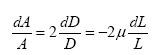
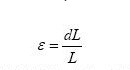
Where μ is the Poisson's ratio of the wire material. dL/L is the relative change in the length of the metal wire, expressed in strain, namely:
The change in resistance value produced during the elongation of the resistance wire is:
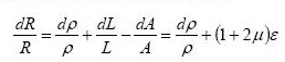
In the formula, the former term is caused by the change of resistivity after the metal wire is deformed; the latter term is caused by the change of the geometrical size after the metal wire is deformed. At room temperature, for many metal materials within a certain strain range, the relative resistance change of the resistance wire is proportional to the relative change of the axial length of the wire. which is:
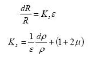
In the formula, Ks is the sensitivity coefficient of a single wire. It means that the resistance change rate of the metal wire has a linear relationship with its axial strain. According to this law, materials that can produce resistance changes during deformation are used to manufacture resistance strain gauges that convert strain signals into electrical signals.
III. Common Types
1. Wire-wound strain gauge

The wire-wound strain gauge has a high fatigue life and strain limit and can be used as a strain conversion element of a sensor for dynamic testing. The wire-wound strain gauge uses a paper base and paper cover, which is low in cost and easy to install. However, because the lateral part of the strain gauge sensitive grid is arc-shaped, its lateral effect is large, and the measurement accuracy is poor. Moreover, the end arc part is difficult to manufacture, and the shape is not easy to ensure the same shape, which makes the performance of the strain gauge dispersed. The room temperature strain measurement is gradually being replaced by other types.
2. Short-circuit strain gauge
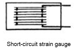
There are also paper-based and gum-based types of short-circuit strain gauges. The short-connection strain gauge is shorted by thick copper wires in the transverse direction, so the lateral effect coefficient is very small (<0.1%), which is the biggest advantage of the short-connection strain gauge. In addition, the shape of the sensitive grid is easier to ensure during the manufacturing process, so the measurement accuracy is high. However, due to its many solder joints, the cross-section changes drastically at the solder joints, so this strain gauge has a short fatigue life.
3. Metal foil strain gauge
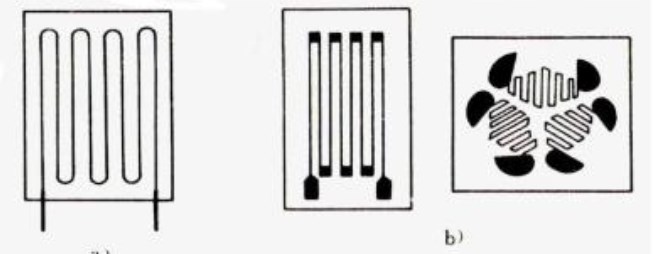
The sensitive grid of the foil strain gauge is made of copper-nickel alloy or nickel-chromium alloy metal foil with a thickness of 0.002~0.005 mm, which is made by the process of engraving, plate making, photolithography, and corrosion (see Figure 2-5). The base is coated with resin glue on the other side of the foil and polymerized by heating. The thickness of the base is generally 0.03-0.05mm.
Compared with wire-wound strain gauges, the advantages of foil strain gauges are:
- The sensitive grid is very thin, and the contact area between the foil and the adhesive layer is larger than that of the wire, so it is firmly pasted and is conducive to deformation transmission, so the strain state it feels is closer to the strain state on the surface of the specimen, High measurement accuracy;
- The sensitive grid is thin and wide. Under the condition of the same cross-sectional area, the surface area of the foil grid is larger than that of the wire grid, and the heat dissipation is good, so it allows a larger current to pass, so it can output a stronger signal and improve measurement Sensitivity
- The lateral ends of the sensitive grid are wider bars, so the lateral effect is small;
- The foil type sheet can ensure accurate size and uniform lines, so the sensitivity coefficient is small;
- Foil strain gauges have small creep and long fatigue life;
- Good processing performance, can be made into strain gauges of various shapes and sizes, especially strain gauges with small grid length or special sensitive grid patterns;
- The manufacturing process is automated, mass production is possible, and the production efficiency is high.
Because foil strain gauges have many of the above advantages, they are widely used in various measurement fields. There is a tendency to gradually replace wire-wound strain gauges in strain measurement at room temperature.
 UTMEL
UTMEL
We are the professional distributor of electronic components, providing a large variety of products to save you a lot of time, effort, and cost with our efficient self-customized service. careful order preparation fast delivery service
What is the use of strain gauge?
A strain gauge is a type of electrical sensor. It's primary use is to measure force or strain. The resistance of a strain gauge changes when force is applied and this change will give a different electrical output. Strain gauges use this method to measure pressure, force, weight and tension.
What is the output of strain gauge?
Strain gauges convert the applied force, pressure, torque, ect., into an electrical signal which can be measured. Force causes strain, which is then measured with the strain gauge by way of a change in electrical resistance. Then the voltage measurement is gathered using data acquisition.
What is strain gauge factor?
Gauge factor (GF) or strain factor of a strain gauge is the ratio of relative change in electrical resistance R, to the mechanical strain & epsilon
 The Key Role of Electronic Components in IoT DevicesUTMEL01 September 20235599
The article discusses the pivotal role of electronic components in Internet of Things (IoT) devices. IoT devices work by capturing real-world data using sensors, processing it through a microcontroller, and then sending it to the cloud for further analysis.
Read More How to Identify the Perfect Proximity Sensor for Your ApplicationUTMEL19 July 20251510
Find the best proximity sensors for your project by evaluating material, sensing range, environment, and system needs to ensure optimal performance and reliability.
Read More Trusted Vibration Sensors for Homeowners and Industry ProfessionalsUTMEL17 July 20251190
Compare top vibration sensors for home and industrial use. Find trusted options for security, predictive maintenance, and equipment protection.
Read More Wiring and Mounting Photoelectric Sensors in 2025UTMEL15 July 20251411
Wire and mount photoelectric sensors in 2025 with step-by-step safety, wiring, and alignment tips for reliable installation and optimal sensor performance.
Read More Essential Tips for Picking the Best Gas SensorUTMEL15 July 20252730
Find out how to select gas sensors by matching target gases, environment, and compliance needs for reliable and accurate gas detection in any setting.
Read More
Subscribe to Utmel !