Product
 Brand
Brand Articles
 Tools
Tools

LED Series Resistor Calculator Overview
The LED Series Resistor Calculator determines the resistance and resistor power required to limit current through one LED or a series string of LEDs supplied from a voltage source. Enter the supply voltage, LED forward voltage, target current, and number of series LEDs to estimate a suitable resistor value.
A series resistor is a simple current-limiting method for low-current indicator LEDs when the supply voltage is reasonably stable. It is not a constant-current regulator. LED forward voltage, supply variation, resistor tolerance, temperature, and driver voltage drop all affect the actual current.
Use the LED manufacturer's datasheet to select forward current and forward-voltage limits. Do not assume that every indicator LED should operate at 20 mA, and do not design from LED color alone.
LED Series Resistor Circuit
The resistor, LED, and voltage source form one series current path. The resistor drops the voltage remaining after the LED forward voltage is subtracted from the supply.

Calculator Inputs
| Input | Meaning | Typical Unit |
|---|---|---|
| Supply voltage, VS | The voltage applied to the LED and resistor circuit. | V |
| LED forward voltage, VF | The forward voltage of one LED at the intended current and operating condition. | V |
| LED current, IF | The target forward current selected from the LED datasheet and application requirements. | A or mA |
| Number of series LEDs, N | The number of LEDs connected in the same series current path. | Unitless |
| Additional series voltage drop | An optional driver, transistor, switch, or output-pin voltage drop. | V |
Calculator Outputs
| Output | Meaning | Unit |
|---|---|---|
| Calculated resistance | The resistance required for the selected nominal voltage and current. | Ω |
| Resistor voltage | The voltage remaining across the resistor. | V |
| Resistor power | The nominal power dissipated by the resistor. | W |
| LED power | An ideal estimate of electrical power in the LED at the selected operating point. | W |
Single LED Series Resistor Formula
For one LED connected directly in series with a resistor:
R = (VS - VF) / IF
Where:
R = required series resistance in ohms
VS = supply voltage in volts
VF = LED forward voltage at the intended current in volts
IF = target LED forward current in amperes
Convert milliamperes to amperes before using the formula:
I in amperes = I in milliamperes / 1000
Multiple LEDs in Series
LEDs in the same series string carry the same current. Add their forward voltages before calculating the resistor:
R = (VS - VF1 - VF2 - ... - VFN) / IF
If the LEDs are treated as having the same forward voltage:
R = (VS - N × VF) / IF
The supply voltage must exceed the total LED forward voltage plus any driver voltage drop and enough resistor voltage to control current. If the calculated resistor voltage is zero or negative, that LED string cannot reach the target current from the stated supply using this circuit.
Including a Driver or Switch Voltage Drop
A transistor, logic output, open-drain driver, or current-sink output may have a nonzero voltage drop. Include it in the calculation:
R = (VS - ΣVF - VDRIVER) / IF
Use the driver voltage specified at the intended current rather than assuming an ideal 0 V switch. Also verify the output pin's current, voltage, and total package limits.
LED Forward Voltage Is Not Fixed
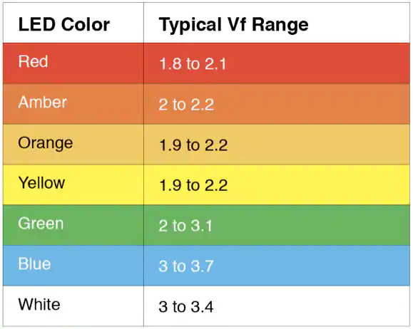
LED forward voltage depends on semiconductor material, current, temperature, manufacturer, production variation, and device construction. Color may suggest a broad voltage range, but it is not a precise design parameter.
Use the datasheet values for the specific part number. For worst-case current checks, the minimum forward voltage is usually the critical value because it leaves more voltage across the resistor and produces more current.

The chart above is retained from the original page as a general reference only. Do not use a color-based typical voltage in place of the minimum, typical, and maximum VF values from the actual LED datasheet.
How to Select LED Current
Select current from the LED datasheet and the required brightness, not from a universal rule. Check:
Recommended or test forward current
Absolute maximum continuous forward current
Permitted pulse current, pulse width, and duty cycle
Luminous intensity or flux at the intended current
Junction and ambient temperature limits
Driver or GPIO current capability
Modern high-efficiency indicator LEDs may be bright at currents well below 20 mA. High-power LEDs may require hundreds of milliamperes or more, but they normally need a regulated constant-current driver and proper thermal design rather than a simple resistor.
Resistor Power Calculation
The resistor voltage is:
VR = VS - ΣVF - VDRIVER
Resistor power can be calculated in any equivalent form:
PR = VR × IF
PR = IF2 × R
PR = VR2 / R
Select a resistor whose power rating remains adequate at the expected ambient temperature and PCB conditions. Apply the resistor manufacturer's derating curve and allow practical thermal margin. A fixed rule such as always choosing two to ten times the calculated power is not a substitute for checking the actual component rating and temperature rise.
Single LED Example
A 5 V supply drives an LED with VF = 2.0 V at a target current of 10 mA.
Convert current to amperes:
10 mA = 0.010 A
Calculate resistance:
R = (5 - 2) / 0.010 = 300 Ω
Calculate resistor power:
PR = 3 × 0.010 = 0.030 W
A standard 300 Ω resistor gives the nominal 10 mA result. Select the power rating after checking worst-case voltage, tolerance, ambient temperature, and derating.
Multiple Series LED Example
A 12 V supply drives three LEDs in series. Each LED has a nominal forward voltage of 3.0 V at 20 mA.
Total LED voltage:
ΣVF = 3 × 3.0 = 9.0 V
Series resistance:
R = (12 - 9) / 0.020 = 150 Ω
Resistor power:
PR = 3 × 0.020 = 0.060 W
This is a nominal calculation. The final design must be checked using the minimum and maximum forward voltages and supply limits.
Choosing the Nearest Standard Resistor
If the exact calculated resistance is unavailable, selecting the next higher standard value normally reduces current and provides a conservative starting point. Recalculate the actual current with the chosen value:
IF = (VS - ΣVF - VDRIVER) / RSELECTED
Standard Value Example
A 9 V supply drives two LEDs, each with VF = 2.1 V, at a target of 15 mA:
R = (9 - 4.2) / 0.015 = 320 Ω
If 330 Ω is selected:
I = (9 - 4.2) / 330 = 0.01455 A = 14.55 mA
The nominal resistor power is approximately:
PR = 4.8 × 0.01455 = 0.0698 W
Worst-Case Current Calculation
The nominal resistor value alone does not guarantee the maximum LED current. For a resistor-limited series string, the highest current generally occurs with maximum supply voltage, minimum LED forward voltage, minimum driver drop, and minimum resistor value:
IMAX = (VS,MAX - ΣVF,MIN - VDRIVER,MIN) / RMIN
The lowest current generally occurs with minimum supply voltage, maximum LED forward voltage, maximum driver drop, and maximum resistor value:
IMIN = (VS,MIN - ΣVF,MAX - VDRIVER,MAX) / RMAX
Verify that IMAX stays within the selected operating current and all device limits, while IMIN still provides acceptable brightness.
Resistor Tolerance Example
For a resistor with nominal value R and tolerance T expressed as a decimal:
RMIN = R × (1 - T)
RMAX = R × (1 + T)
A 330 Ω resistor with 5% tolerance may range from 313.5 Ω to 346.5 Ω before additional temperature effects are considered.
Parallel LEDs Need Separate Current Control
Do not assume identical LEDs connected directly in parallel will share current equally. Small forward-voltage differences can cause one LED to carry more current than another. For low-current indicator circuits, give each parallel LED or each parallel series string its own resistor.
One LED per branch: calculate one resistor for each LED.
Several LEDs in series per branch: calculate one resistor for each series string.
Multiple branches: add the branch currents to determine total supply and driver current.
A single resistor shared by several parallel LEDs does not provide independent current balancing.
Driving LEDs from GPIO Pins
When an LED is driven by a microcontroller or logic device, the available output voltage may change with current. Check the device datasheet for guaranteed high-level or low-level output voltage at the selected current.
Verify the maximum current per pin.
Verify total current limits for the port and package.
Include VOH, VOL, transistor saturation voltage, or driver headroom in the resistor calculation.
Check whether the pin sources or sinks LED current.
Use an external transistor or LED driver when the required current exceeds the logic output capability.
PWM Brightness Control
Pulse-width modulation changes average brightness by switching the LED current on and off. The series resistor still needs to limit the instantaneous on-state current. Reducing PWM duty cycle does not make an excessive peak current safe unless the LED datasheet explicitly permits the pulse amplitude, duration, repetition rate, and thermal conditions.
When to Use a Constant-Current LED Driver
A regulated LED driver is usually a better choice when:
The LED operates at high current or high power.
The supply voltage varies widely.
Brightness must remain consistent over temperature and production variation.
Several LED strings require matched current.
Efficiency is important.
The available voltage headroom across a resistor is small.
Dimming, open-LED protection, short-circuit protection, or thermal regulation is required.
High-power LEDs also require suitable heatsinking, PCB thermal design, and junction-temperature verification.
How to Use the LED Series Resistor Calculator
Find the LED's intended forward current and forward-voltage range in its datasheet.
Enter the supply voltage.
Enter the forward voltage of one LED.
Enter the number of LEDs in the series string.
Enter the target current using the correct unit.
Include any switch or driver voltage drop when applicable.
Calculate the resistance and nominal resistor power.
Select a standard resistor and recalculate actual current.
Repeat the calculation with worst-case supply, VF, driver drop, and resistor tolerance.
Check resistor derating, LED thermal limits, and driver current limits.
Common LED Resistor Calculation Mistakes
Entering current in milliamperes without converting it to amperes.
Assuming every indicator LED should operate at 20 mA.
Using LED color as the only source of forward voltage.
Using typical VF without checking minimum VF for maximum current.
Forgetting to add forward voltages for series LEDs.
Using one resistor for directly paralleled LEDs.
Ignoring GPIO or transistor voltage drop and current limits.
Checking resistance but not resistor power.
Ignoring supply tolerance and resistor tolerance.
Assuming PWM duty cycle removes the need to limit peak current.
Using a simple resistor for a high-power LED without current regulation and thermal design.
Frequently Asked Questions
Why does an LED need a series resistor?
An LED has a steep current-voltage relationship. A small voltage change can produce a large current change, so a resistor limits current when the LED is driven from a voltage source.
What is the LED resistor formula?
For one LED, R = (VS - VF) / IF. For a series string, subtract the sum of all LED forward voltages and any driver voltage drop.
Should I always use 20 mA?
No. Select current from the specific LED datasheet and required brightness. Many indicator LEDs operate effectively below 20 mA, while high-power LEDs require dedicated current regulation.
Which forward voltage should I use?
Use the datasheet value at the intended current and temperature. Check minimum VF for maximum-current analysis and maximum VF for minimum-current and voltage-headroom analysis.
Can several LEDs share one resistor?
LEDs in one series string can share one resistor because they carry the same current. Parallel LEDs or parallel strings should normally have separate resistors or regulated branch currents.
What happens if the supply voltage is below the total LED forward voltage?
The desired current cannot be established by the resistor calculation. The LEDs may be dim, off, or highly sensitive to component variation.
How do I choose the resistor power rating?
Calculate worst-case resistor dissipation, then choose a rating that remains adequate after applying the manufacturer's temperature and mounting derating guidance.
Does PWM eliminate the need for a resistor?
No. PWM controls average brightness, but the on-state current still needs to be limited by a resistor or regulated driver.
Can a resistor regulate a high-power LED?
A resistor may be inefficient and provide poor current control as voltage and temperature change. A constant-current LED driver is normally preferred for high-power LEDs.