What is a Schmitt Trigger?

Schmitt Trigger Explained
Catalog |
Overview
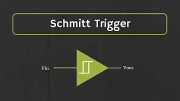
In electronics, the Schmitt trigger is a comparator circuit that includes positive feedback. It is a threshold switch circuit, a gate circuit with abrupt input-output characteristics. This circuit is designed to prevent changes in output voltage caused by small changes in input voltage (below a certain threshold).
For standard Schmitt triggers, when the input voltage is higher than the positive threshold voltage, the output is high; when the input voltage is lower than the negative threshold voltage, the output is low; when the input is between the positive and negative threshold voltages, the output does not change. This means that the threshold voltages are different when the output is flipped from high to low parity or from low to high parity. Only when the input voltage changes enough, the output will change. So this kind of component is named trigger. This double-threshold action is called hysteresis, indicating that the Schmitt trigger has memory. In essence, the Schmitt trigger is a bistable multivibrator.
The Schmitt trigger can be used as a waveform shaping circuit, which can shape the analog signal waveform into a square wave that can be processed by a digital circuit. And because the Schmitt trigger has hysteresis characteristics, it can be used for anti-interference. Its applications include anti-interference in an open-loop configuration and a multivibrator in a closed-loop positive feedback/negative feedback configuration.
How to implement Schmitt trigger?
Tunnel diode
The Schmitt trigger can be realized with a simple tunnel diode. The volt-ampere characteristic of this diode is an "N"-shaped curve in the first quadrant. The oscillating input will cause the volt-ampere characteristic of the diode to move from the rising branch of the "N"-shaped curve to another branch and then return to the starting point when the input value exceeds the rising and falling flip thresholds. However, the performance of this type of Schmitt trigger can be improved by using transistor-based components, because transistor-based components can directly use positive feedback to improve flipping performance.
Comparators
Schmitt triggers are often implemented by connecting positive feedback comparators. For this circuit, the flip occurs close to the ground, and the amount of hysteresis is controlled by the resistance of R1 and R2.
The comparator extracts the sign of the difference between the two inputs. When the voltage of the non-inverting (+) input is higher than the voltage of the inverting (-) input, the output of the comparator flips to the high operating voltage +Vs; when the voltage of the non-inverting (+) input is lower than the voltage of the inverting (-) input, the output of the comparator flips to the low operating voltage -Vs. The inverting (-) input here is grounded, so the comparator here implements the function symbol, which has the characteristics of a two-state output. There are only two states of high and low. When the non-inverting (+) terminal is continuously input, there will always be the same symbol.
Since the resistor network connects the input terminal of the Schmitt trigger with the output terminal of the comparator, the Schmitt trigger behaves like a comparator and can flip the level at different times. It depends on whether the output of the comparator is high or low. If the input is a negative input with a large absolute value, the output will be low; if the input is a positive input with a large absolute value, the output will be high, which realizes the function of a non-inverting Schmitt trigger. However, for an input whose value is between two thresholds, the output state depends on both the input and the output. For example, if the current state of the Schmitt trigger is high, the output will be on the positive power +Vs. At this time, V+ will become a voltage divider between Vin and +Vs. In this case, the comparator will flip to a low level only when V+=0 (grounded). From the conservation of current, it can be seen that the following relationship is satisfied at this time:

Therefore, it must be lowered below -R1Vs/R2 before the output will reverse. Once the output of the comparator flips to −Vs, the threshold for flipping back to the high level becomes +R1Vs/R2. In this way, the circuit forms a section of the switching voltage band around the origin, and the trigger level is ±R1Vs/R2. Only when the input voltage rises to the upper limit of the voltage band, the output will flip to a high level; only when the input voltage drops to the lower limit of the voltage band, the output will flip back to a low level. If R1 is 0, R2 is infinite (ie, open circuit). And the width of the voltage band will be compressed to 0. At this time, the circuit becomes a standard comparator. The output characteristics are shown on the right. The threshold T is given by R1Vs/R2, and the maximum value of the output M is the power rail. The actual configuration of the non-inverting Schmitt trigger circuit is shown in the Figure below.

Non-inverting Schmitt trigger circuit
The output characteristic curve has the same shape as the output curve of the above-mentioned basic configuration, and the threshold value also satisfies the same relationship as the above-mentioned configuration. The difference is that the output voltage of the above example depends on the power supply, while the output voltage of this circuit is determined by two Zener diodes. In this configuration, the output level can be changed by selecting an appropriate Zener diode, and the output level is resistant to power fluctuations, that is to say, the output level improves the power supply voltage rejection ratio (PSRR) of the comparator. The resistor R3 is used to limit the current through the diode, and the resistor R4 reduces the input offset voltage caused by the input leakage current of the comparator to a minimum.
Two transistors
In the Schmitt trigger implemented using the positive feedback configuration, most of the complex functions that the comparator itself can implement are not used. Therefore, the circuit can be implemented with two cross-coupled transistors. The Schmitt trigger circuit based on 2 transistors is shown in the Figure below. The path RC1 R1 R2 sets the base voltage of the transistor T2, but this voltage divider path will be affected by the transistor T1. If T1 is open, the path will provide a higher voltage. Therefore, the threshold voltage that flips between the two states depends on the current state of the flip-flop.

Schmitt trigger circuit based on 2 transistors
For the NPN transistor shown above, when the input voltage is much lower than the common-emitter voltage, T1 will not turn on. The base voltage of the transistor T2 is determined by the aforementioned voltage divider circuit. Due to the access to negative feedback, the voltage applied to the common emitter must be almost as high as the voltage determined on the voltage divider circuit, so that T2 can be turned on, and the output of the trigger is in a low-level state. When the input voltage (T1 base voltage) rises slightly higher than the voltage (emitter voltage) on the resistor RE, T1 will be turned on. When T1 starts to turn on, T2 is no longer turned on, because the voltage provided by the voltage divider path is lower than the base voltage of T2. And the emitter voltage will not decrease, because T1 consumes current through RE at this time. At this time, T2 is not turned on, and the flip-flop transitions to a high-level state.
At this time, the flip-flop is in a high-level state. If the input voltage drops sufficiently, the current through T1 will decrease, which will reduce the common emitter voltage of T2 and increase its base voltage. When T2 starts to conduct, the voltage on RE rises, and then the base-emitter potential of T1 is reduced, and T1 is no longer conducting.
In the high-level state, the output voltage is close to V+; but in the low-level state, the output voltage will still be much higher than V−. Therefore, in this case, the output voltage is not low enough to reach the logic low level, which requires an additional amplifier on the flip-flop circuit.
The above circuit can be simplified: R1 can be replaced by a short-circuit connection so that the base of T2 is directly connected to the collector of T1, and R2 can be removed and replaced with an open circuit. The key to circuit operation is that when T1 is turned on (the result of current input to the base), the current through RE is smaller than when T1 is turned off, because when T1 is turned on, T2 will be turned off. When T2 is turned on, compared to T1, it provides RE with a greater passing current. When the current flowing into the RE decreases, the voltage on it will decrease, so once the current starts to flow into T1, the input voltage must decrease to make T1 return to the off state, because the emitter voltage of T1 has dropped at this time. This Schmitt trigger buffer can also be turned into a Schmitt trigger inverter, and a resistor can be omitted in the process by replacing RK2 with a short circuit and connecting Vout to the emitter of T2 Instead of the collector.
However, in this case, the resistance of RE should be larger, because RE should act as a pull-down resistor at the output. Its function is that when the output should be low, it will reduce the voltage at the output. If the resistance of RE is small, only a small voltage can be produced on it. When the output should be a digital low level, this voltage will actually increase the output voltage.
Applications
1. Waveform transformation
Triangular waves, sine waves, periodic waves, etc. can be transformed into rectangular waves.
2. Shaping of pulse wave
In digital systems, rectangular pulses often undergo waveform distortion during transmission, and the rising and falling edges are not ideal. After shaping by Schmitt trigger, a more ideal rectangular pulse can be obtained.
3. Pulse amplitude discrimination
When pulse signals with different amplitudes and irregularities are applied to the input terminal of the Schmitt trigger, pulse signals with an amplitude greater than a preset value can be selected for output.
4. Form a multivibrator
Signals with different amplitudes will generate rectangular pulses after passing through a Schmitt trigger with a suitable capacitor. Rectangular wave pulse signals are often used as pulse signal sources and clock signals in sequential circuits.
Commonly used chips
74LS18 dual four-input NAND gate (Schmitt trigge)
74LS14 six inverters (Schmitt trigge)
74132, 74LS132, 74S132, 74F132, 74HC132 2-input four-and non-Schmitt trigger
74221, 74LS221, 74 HC221, 74 C221 double monostable multivibrators (with Schmitt trigger)
Schmitt trigger can be formed with 555 timer
CD4093 consists of four 2-input Schmitt triggers
1. What is a Schmitt trigger used for?
Schmitt trigger devices are typically used in signal conditioning applications to remove noise from signals used in digital circuits, particularly mechanical contact bounce in switches.
2. What is other name of Schmitt trigger?
The Schmitt trigger circuit uses positive feedback. Therefore, this circuit is also known as the regenerative comparator circuit. The Schmitt Trigger circuit can be designed with the help of Op-Amp and Transistor. And it classified as; Op-amp based Schmitt trigger.
 Discovering New and Advanced Methodology for Determining the Dynamic Characterization of Wide Bandgap DevicesSaumitra Jagdale15 March 20242346
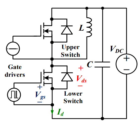
For a long era, silicon has stood out as the primary material for fabricating electronic devices due to its affordability, moderate efficiency, and performance capabilities. Despite its widespread use, silicon faces several limitations that render it unsuitable for applications involving high power and elevated temperatures. As technological advancements continue and the industry demands enhanced efficiency from devices, these limitations become increasingly vivid. In the quest for electronic devices that are more potent, efficient, and compact, wide bandgap materials are emerging as a dominant player. Their superiority over silicon in crucial aspects such as efficiency, higher junction temperatures, power density, thinner drift regions, and faster switching speeds positions them as the preferred materials for the future of power electronics.
Read More A Comprehensive Guide to FPGA Development BoardsUTMEL11 September 20257980
This comprehensive guide will take you on a journey through the fascinating world of FPGA development boards. We’ll explore what they are, how they differ from microcontrollers, and most importantly, how to choose the perfect board for your needs. Whether you’re a seasoned engineer or a curious hobbyist, prepare to unlock new possibilities in hardware design and accelerate your projects. We’ll cover everything from budget-friendly options to specialized boards for image processing, delve into popular learning paths, and even provide insights into essential software like Vivado. By the end of this article, you’ll have a clear roadmap to navigate the FPGA landscape and make informed decisions for your next groundbreaking endeavor.
Read More Applications of FPGAs in Artificial Intelligence: A Comprehensive GuideUTMEL29 August 20252199
This comprehensive guide explores FPGAs as powerful AI accelerators that offer distinct advantages over traditional GPUs and CPUs. FPGAs provide reconfigurable hardware that can be customized for specific AI workloads, delivering superior energy efficiency, ultra-low latency, and deterministic performance—particularly valuable for edge AI applications. While GPUs excel at parallel processing for training, FPGAs shine in inference tasks through their adaptability and power optimization. The document covers practical implementation challenges, including development complexity and resource constraints, while highlighting solutions like High-Level Synthesis tools and vendor-specific AI development suites from Intel and AMD/Xilinx. Real-world applications span telecommunications, healthcare, autonomous vehicles, and financial services, demonstrating FPGAs' versatility in mission-critical systems requiring real-time processing and minimal power consumption.
Read More 800G Optical Transceivers: The Guide for AI Data CentersUTMEL24 December 20251027
The complete guide to 800G Optical Transceiver standards (QSFP-DD vs. OSFP). Overcome supply shortages and scale your AI data center with Utmel Electronic.
Read More Xilinx FPGAs: From Getting Started to Advanced Application DevelopmentUTMEL09 September 20252887
This guide is your comprehensive roadmap to understanding and mastering the world of Xilinx FPGA technology. From selecting your first board to deploying advanced AI applications, we'll cover everything you need to know to unlock the potential of these remarkable devices. The global FPGA market is on a significant growth trajectory, expected to expand from USD 8.37 billion in 2025 to USD 17.53 billion by 2035. This surge is fueled by the relentless demand for high-performance, adaptable computing in everything from 5G networks and data centers to autonomous vehicles and the Internet of Things (IoT). This guide will walk you through the key concepts, tools, and products in the Xilinx ecosystem, ensuring you're well-equipped to be a part of this technological revolution.
Read More
Subscribe to Utmel !
![AT88SC25616C-PU]() AT88SC25616C-PU
AT88SC25616C-PUMicrochip Technology
![FM3164-G]() FM3164-G
FM3164-GCypress Semiconductor Corp
![HCS301-I/P]() HCS301-I/P
HCS301-I/PMicrochip Technology
![L9660TR]() L9660TR
L9660TRSTMicroelectronics
![MOC3062VM]() MOC3062VM
MOC3062VMON Semiconductor
![MOC3020SR2M]() MOC3020SR2M
MOC3020SR2MON Semiconductor
![FGBS3040E1-F085]() FGBS3040E1-F085
FGBS3040E1-F085ON Semiconductor
![ATSHA204-TSU-T]() ATSHA204-TSU-T
ATSHA204-TSU-TMicrochip Technology
![AD8196ACPZ]() AD8196ACPZ
AD8196ACPZAnalog Devices Inc.
![TLE8110EDXUMA1]() TLE8110EDXUMA1
TLE8110EDXUMA1Infineon Technologies


