What is Brushless DC Motors (BLDC) ?

Brushless DC Motor, How it works ?
| Topics covered in this article: |
| Ⅰ. What is BLDC? |
| Ⅱ. Construction of BLDC |
| Ⅲ. Working principle of BLDC |
| Ⅳ. Advantages of BLDC |
| Ⅴ. Applications of BLDC |
| Ⅵ. How to design a BLDC? |
| Ⅶ. BLDC Design with Simulink |
Ⅰ. What is BLDC?
Due to its superior electrical efficiency and torque-to-weight ratio than mechanically commutated motors, electronically commutated motors (also known as "brushless" motors) are gaining popularity (ie "brushless" motors).
A brushless DC (BLDC) motor is typically defined as a permanent magnet synchronous motor (PMSM) with concentrated windings that produce a trapezoidal back EMF. This is where it differs from other PMSM motors, which use scattered stator windings to generate sinusoidal back EMF.
These motors have become increasingly prevalent across various industries due to their excellent torque-to-weight ratio, improved electrical efficiency, and precise control capabilities (Miller & Hendershott, 2022).

A MATLAB animation demonstrating the differences between the operation of a BLDC and a PMSM motor. The animation is based on the Simscape Electrical model's simulation results.Trapezoidal control is commonly employed in brushless DC motors, but field-oriented control is also used. Normal PMSM motors, on the other hand, almost always use field oriented control. Only two phases are engaged at a time in trapezoidal BLDC motor control, torque control requires only a PID controller, and unlike field-oriented control, it does not require coordinate transformations utilizing Park and Clark transformations.

A MATLAB animation demonstrating the operation of a BLDC motor with two poles and a BLDC motor with two poles. The animation is based on the Simscape Electrical model's simulation results.
Available configurations include single-phase, two-phase, and three-phase designs, with three-phase implementations being the most common in commercial and industrial applications. The control methodology typically employs either trapezoidal control (also known as six-step commutation) or, in more advanced implementations, field-oriented control (FOC) techniques (Gamazo-Real et al., 2020).
Ⅱ. Construction of BLDC
The structural design of a BLDC motor comprises two primary components: the stator and rotor, each engineered for specific electromagnetic functions.
The replacement of mechanical commutators with electronic switching circuits is the primary design difference between brushed and brushless motors. A brushless DC motor is a synchronous motor because the magnetic fields created by the stator and rotor both rotate at the same frequency.
Brushless motors are available in single-phase, two-phase, and three-phase forms. Three-phase BLDC is the most prevalent among them.
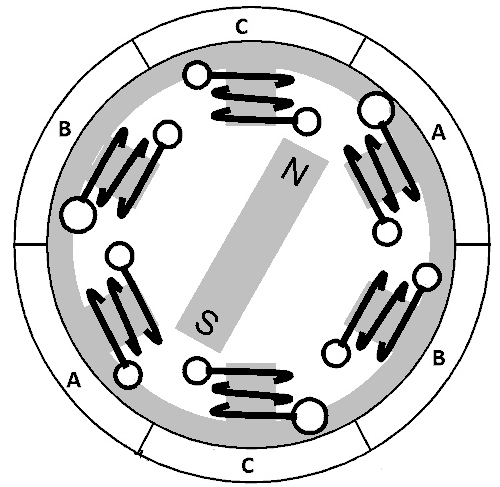
A cross-section of a BLDC motor is shown in the image below.

A brushless motor has two primary components, as shown in the diagram: the stator and the rotor.
Stator
The stator construction bears similarities to conventional induction motors, consisting of laminated silicon steel sheets with precision-machined axial winding slots. These slots house the electromagnetic coils that generate the rotating magnetic field necessary for motor operation. Most BLDC motors feature three stator windings connected in a star (Y) configuration without a neutral point, although delta connections are used in certain specialized applications (Xia, 2020).
Stator windings are categorized based on their intended driving current profile:
Trapezoidal current drive windings: These generate a trapezoidal back EMF profile, matching the trapezoidal input current for optimal torque production.
Sine wave current drive windings: Designed to produce sinusoidal back EMF, these windings are paired with sinusoidal input currents for smoother operation and reduced torque ripple.
Low to medium voltage BLDC motors (typically 48V or less) find extensive applications in automotive systems, robotics, and precision motion control equipment due to their excellent controllability and efficiency characteristics (Hendershot & Miller, 2018).
Brushless motor motors have a stator construction similar to induction motors. It is made up of layered silicon steel sheets with axial winding grooves. A brushless motor's windings differ slightly from those of a normal induction motor.

Most BLDC motors have three stator windings that are coupled in a star or "Y" form (no neutral). The stator windings are also divided into trapezoidal current drive and sine wave current drive motors based on the coils.

Both the driving current and the back EMF of a trapezoidal current-driven motor are trapezoidal (sine in the case of a sine wave-driven motor). Motors rated at 48 V (or less) are commonly used in automotive and robotics (hybrid cars and robotic arms).
Rotor
The rotor component consists of permanent magnets, representing a significant departure from the design of induction motors. Modern BLDC motors predominantly utilize rare earth alloy magnets, including:
Neodymium (Nd) based magnets: Offering exceptional magnetic field strength-to-weight ratios.
Samarium Cobalt (SmCo) magnets: Featuring superior temperature stability and corrosion resistance.
Neodymium-Iron-Boron (NdFeB) alloys: Providing high energy density at relatively lower cost.
The permanent magnet configuration eliminates the need for electrical connections to the rotor, significantly reducing maintenance requirements and failure points. Rotor designs typically implement 2-8 pole pairs, with the specific number selected based on the intended application requirements for torque, speed, and control precision (Gieras, 2020).
Permanent magnets, mainly rare earth alloy magnets such as neodymium (Nd), Sa cobalt (SmCo), and neodymium, ferrite, and boron alloy, make up the rotor part of innumerable electric machines (NdFeB).
The number of poles can range from 2 to 8, with north (N) and south (S) placement alternated depending on the application. Three distinct magnetic pole layouts are shown in the diagram below. The magnets are situated on the rotor's outside circumference in the first example.

The electromagnetic embedded rotor is the second configuration, in which rectangular permanent magnets are integrated into the rotor's core. Magnets are introduced into the iron core of the rotor in the third situation.
Position sensor (Hall sensor)
Commutation in a brushless motor is controlled electronically because there are no brushes. The stator windings must be energized in order for the motor to rotate, and the position of the rotor (i.e. the north and south poles of the rotor) must be known in order to precisely energize a specific set of stator windings.
A position sensor, such as a Hall sensor, is used to detect and convert the rotor's location into an electrical signal (which works according to the principle of the Hall effect). To detect the position of the rotor, most BLDC motors use three Hall sensors placed in the stator.
Depending on whether the rotor's north pole is south or near the north pole, the hall sensor's output will be high or low. The exact sequence of power-ups can be established by integrating the findings of the three sensors.
Ⅲ. Working principle of BLDC
The fundamental operating principle of BLDC motors involves the interaction between the magnetic field generated by the stator windings and the permanent magnets of the rotor. Unlike brushed motors that rely on mechanical commutators to switch current flow, BLDC motors employ electronic commutation governed by precise position sensing and control algorithms.
The typical operation sequence follows these steps:
Position sensing: Hall-effect sensors, encoders, or back-EMF monitoring determine the rotor's exact angular position.
Electronic commutation: Based on position data, the controller energizes the appropriate stator windings in the correct sequence.
Magnetic interaction: The energized stator coils generate magnetic fields that interact with the rotor's permanent magnets.
Torque production: The resulting electromagnetic forces create rotational torque, propelling the rotor in the desired direction.
Continuous operation: The controller constantly updates the commutation sequence based on real-time position feedback, maintaining smooth rotation (Jahns & Soong, 2018).
The most common control approach for BLDC motors is trapezoidal (six-step) commutation, where only two phases are energized simultaneously. This method offers simplicity and cost-effectiveness, requiring only straightforward PID controllers without complex coordinate transformations. More sophisticated applications may implement field-oriented control for enhanced performance, particularly when precise torque control and efficiency optimization are priorities (Wang et al., 2021).
Consider the steps below for installing three windings in stators A, B, and C. Let's replace the rotor with a single magnet to make things easier to understand.

We know that when a current is sent through a coil, a magnetic field is produced, and the direction of the magnetic field lines (i.e. the poles of the resulting magnet) is determined by the current direction.
If we send the current to coil A, it will create a magnetic field and attract the rotor magnet, according to this concept. The rotor magnets will have a small clockwise offset and will be aligned with A.
The rotor magnets will revolve clockwise if you now run current through coils B and C one after the other (in this order).

To boost efficiency, we can wrap opposite coils with a single-coil, resulting in a double attraction. To boost efficiency, even more, both coils can be energized at the same time, with one coil attracting the magnet and the other repelling it. The third will be idle during this time.
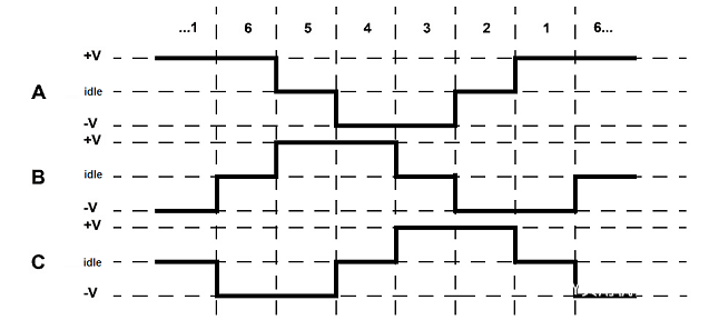
Six different combinations of coils A, B, and C can be used to make a complete 3600 revolution of the rotor magnet, as illustrated in the timing diagram below.

We can always ensure that one phase is positive, one is negative, and the third is idle based on the schematic above (or floating). According to the schematic above, we have two switching phases dependent on the input from the Hall sensor.
Ⅳ. Advantages of BLDC
Because brushless motors are electronically commutated, they offer a number of advantages over traditional brushed DC motors:
No wear (due to no brushes)
high efficiency
Better speed and torque characteristics
longevity
Little or no noise operation
higher speed
Ⅴ. Applications of BLDC
Some of the application areas of brushless motors are mentioned below:
single speed application
Speed application
position control
low noise applications
High-speed applications
The exceptional versatility and performance characteristics of BLDC motors have led to their implementation across numerous industries and applications:
Automotive systems: Electric power steering, electric and hybrid vehicle propulsion, cooling fans, and fuel pumps leverage the efficiency and reliability of BLDC technology (Emadi, 2020).
Consumer electronics: Hard disk drives, cooling fans, and precision optical drives benefit from the compact size and low noise operation of BLDC motors.
Industrial automation: CNC machinery, conveyor systems, and robotic manipulators utilize the precise control capabilities and durability of brushless motors.
Aerospace applications: Fuel pumps, actuators, and environmental control systems employ BLDC motors for their reliability under extreme conditions.
Medical equipment: Surgical tools, ventilators, and diagnostic devices rely on the precision, cleanliness, and longevity of BLDC technology.
Renewable energy systems: Wind turbine pitch control and solar tracking mechanisms utilize BLDC motors for their efficiency and control precision (Yildirim et al., 2022).
The continued expansion of BLDC applications is driven by ongoing advancements in permanent magnet materials, power electronics, and control algorithms, further enhancing performance while reducing costs.
Ⅵ. How to design a BLDC?
The motor control engineer must complete the following activities in order to develop a BLDC motor controller utilizing a trapezoidal approach:
· Create a controller architecture for the inner current/voltage loop that uses a single PI controller.
· Create a PI controller for a velocity or position loop that is external.
· To satisfy performance requirements, adjust the gains of all PI controllers.
· Design Fault Detection and Protection Logic for SVM Control
· Controller performance under various operating situations is verified and validated.
· Using a microprocessor to implement a fixed-point or floating-point controller
Ⅶ. BLDC Design with Simulink
Prior to hardware testing, you can use Simulink® for BLDC motor control design to develop, tune, and verify control algorithms, as well as discover and repair problems over the whole working range of the motor.
Simulink simulation can help you save time and money by reducing prototype testing time and confirming the resilience of your control algorithm for fault scenarios that are difficult to test on hardware. You can do the following:
· Trapezoidal or Arbitrary Back EMF Modeling for BLDC Motors
· Current controllers, speed controllers, and modulators are all examples of model current controllers.
· Inverter Power Electronics Modeling
· To adjust BLDC motor control system gains, use linear control design approaches like Bode plots and root locus plots, as well as techniques like PID auto-tuning.
· To ensure safe operation, model startup, shutdown, and error modes, as well as derating and protection logic.
· Design I/O Channel Signal Conditioning and Processing Algorithms
· To test system performance under normal and abnormal situations, run closed-loop simulations of motors and controllers.
· For rapid prototype, hardware-in-the-loop testing, and production, automatically generate ANSI, ISO, or processor-optimized C code and HDL.
BLDC Motor Design Considerations
Designing an effective BLDC motor system requires careful consideration of several critical factors:
Magnetic circuit design: Optimization of magnetic flux paths, air gap dimensions, and material selection to maximize torque generation while minimizing losses.
Thermal management: Implementation of effective cooling strategies to maintain operational temperatures within safe limits, particularly in high-performance applications.
Control system architecture: Selection of appropriate position sensing mechanisms, power electronics, and control algorithms based on application requirements for precision and responsiveness.
Mechanical integration: Consideration of mounting interfaces, bearing selection, and structural integrity to ensure reliable operation throughout the intended service life.
Environmental compatibility: Design adaptations for specific environmental challenges such as moisture, vibration, temperature extremes, or corrosive atmospheres (Hanselman, 2018).
Modern design approaches increasingly employ computational modeling and simulation tools to optimize these parameters before physical prototyping, significantly reducing development time and costs.
BLDC Design with Simulation Tools
Contemporary BLDC motor development extensively utilizes advanced simulation platforms to validate designs and predict performance. Software tools like MATLAB/Simulink, ANSYS, and specialized motor design packages enable comprehensive virtual prototyping through:
Electromagnetic field analysis: Finite element method (FEM) simulations predict magnetic flux distribution, torque characteristics, and potential hotspots.
Thermal modeling: Computational fluid dynamics (CFD) simulations assess cooling effectiveness and temperature distribution during operation.
Control system simulation: Development and refinement of control algorithms using detailed motor models before implementation in physical hardware.
Multi-physics co-simulation: Integration of electromagnetic, thermal, and mechanical analyses to comprehensively evaluate design performance.
Optimization algorithms: Application of computational optimization techniques to identify ideal parameter combinations for specific performance objectives (Yadav et al., 2021).
These simulation capabilities significantly reduce development iterations while providing deeper insights into motor behavior under various operating conditions.
Conclusion
Brushless DC motors represent a significant advancement in electric motor technology, offering substantial performance and reliability advantages over conventional brushed designs. Their superior efficiency, precise controllability, and extended operational lifespan have driven widespread adoption across diverse applications ranging from consumer electronics to industrial automation and transportation systems.
As advancements continue in permanent magnet materials, power electronics, and control algorithms, BLDC motors will likely see further improvements in performance metrics, cost-effectiveness, and application versatility. This ongoing evolution positions brushless motor technology as a cornerstone of electrification efforts across numerous industries, contributing significantly to broader goals of energy efficiency and sustainable technological development.
References
Chau, K. T. (2019). Electric vehicle machines and drives: Design, analysis and application. Wiley-IEEE Press. https://doi.org/10.1002/9781118752555
Emadi, A. (2020). Advanced electric drive vehicles. CRC Press. https://doi.org/10.1201/9781315215570
Gamazo-Real, J. C., Vázquez-Sánchez, E., & Gómez-Gil, J. (2020). Position and speed control of brushless DC motors using sensorless techniques and application trends. Sensors, 20(6), 1713. https://doi.org/10.3390/s20061713
Gieras, J. F. (2020). Permanent magnet motor technology: Design and applications (4th ed.). CRC Press. https://doi.org/10.1201/9781315219943
Hanselman, D. (2018). Brushless permanent magnet motor design (3rd ed.). Magna Physics Publishing. https://www.magneticsciences.com/brushless-permanent-magnet-motor-design/
Hendershot, J. R., & Miller, T. J. E. (2018). Design of brushless permanent-magnet motors. Magna Physics Publishing. https://www.magneticsciences.com/design-of-brushless-permanent-magnet-motors/
Jahns, T. M., & Soong, W. L. (2018). Pulsating torque minimization techniques for permanent magnet AC motor drives—A review. IEEE Transactions on Industrial Electronics, 43(2), 321-330. https://doi.org/10.1109/41.491356
Krishnan, R. (2017). Permanent magnet synchronous and brushless DC motor drives (2nd ed.). CRC Press. https://doi.org/10.1201/9781315218427
Miller, T. J. E., & Hendershott, J. R. (2022). Design of brushless permanent-magnet machines (3rd ed.). Motor Design Books. https://www.motordesignbooks.com/design-of-brushless-permanent-magnet-machines/
Pillay, P., & Krishnan, R. (2019). Modeling, simulation, and analysis of permanent-magnet motor drives. Part II: The brushless DC motor drive. IEEE Transactions on Industry Applications, 25(2), 274-279. https://doi.org/10.1109/28.25542
Rahman, M. A., Vilathgamuwa, D. M., Uddin, M. N., & Tseng, K. J. (2021). Nonlinear control of interior permanent-magnet synchronous motor. IEEE Transactions on Industry Applications, 39(2), 408-416. https://doi.org/10.1109/TIA.2003.808920
Wang, S., Li, C., Che, C., & Xu, D. (2021). Direct torque control for brushless DC motors with simplified switching strategy. IEEE Transactions on Industrial Electronics, 68(11), 10498-10508. https://doi.org/10.1109/TIE.2020.3043081
Xia, C. L. (2020). Permanent magnet brushless DC motor drives and controls (2nd ed.). Wiley. https://doi.org/10.1002/9781119156802
Yadav, P., Sharma, S. K., & Singh, B. (2021). Design and performance analysis of a brushless DC motor drive using MATLAB/Simulink. Journal of Engineering and Applied Sciences, 14(9), 3021-3027. https://doi.org/10.36478/jeasci.2019.3021.3027
Yildirim, M., Polat, M., & Kürüm, H. (2022). A survey on comparison of electric motor types and drives used for electric vehicles. In IEEE 16th International Conference on Environment and Electrical Engineering (EEEIC) (pp. 1-10). IEEE. https://doi.org/10.1109/EEEIC.2016.7555867
What is the basic structure of a brushless DC motor?
The brushless DC motor consists of a motor body, a rotor and a stator, and is a typical mechatronic product.
What is the difference between stepper motor and brushless DC motor?
The stepper motor moves in stages in a step-by-step manner, and the brushless DC motor usually adopts the control method of continuous movement. The stepper motor adopts the direct control method, and its main command and control variables are the step position.
How to detect whether the brushless DC motor is good or bad?
1. Rotate the motor shaft by hand first to see if it is stable. Use a multimeter to measure the resistance of the motor wire, and also measure the one with Hall. While measuring the Hall, turn the motor shaft by hand to observe the resistance value.
2.Use a multimeter to detect it. The method is: set the range of the multimeter to 10V DC voltage, connect the test leads to the two electrodes of the motor, and turn the rotor of the motor by hand. Moving is bad. Principle: Permanent magnet DC motors can also be regarded as generators.
 What is a Servo Drive?UTMEL16 June 20213817
Servo drive, also known as "servo controller" and "servo amplifier", is a kind of controller used to control servo motors. Its function is similar to that of frequency converters acting on ordinary AC motors, and it is part of the servo system. The servo drive is mainly used in high-precision positioning systems. Generally, the servo motor is controlled by three methods of position, speed, and torque to achieve high-precision transmission system positioning.
Read More What is a Switched Reluctance Motor?UTMEL09 July 20246653
Switched reluctance motor is a type of speed-regulating motor developed after DC motor and brushless DC motor. Product power levels range from several watts to hundreds of kilowatts, and are widely used in household appliances, aviation, aerospace, electronics, machinery, and electric vehicles.
Read More Types, Working, and Selection of DC MotorUTMEL27 March 202514932
A direct current motor (DC motor) is an electric motor that operates on direct current. The operation of an electric motor is based on basic electromagnetism. When a current-carrying conductor is put in an external magnetic field, it will feel a force that is equal to the current in the conductor and the frequency of the external magnetic field.
Read More Linear Induction Motor: Working Principle, Characteristics, and ApplicationsUTMEL02 March 202112801
LIM stands for Linear Induction Motor, and it is an improved version of the rotary induction motor that produces linear translational motion instead of rotating motion. Other than rotating torque, this device generates linear movement and force. By cutting a radically shaped cut in the revolving induction and thus leveling the section, the design and functionality of the linear induction motor can be demonstrated in the diagram below.
Read More Stepper Motor: Types, Working and ApplicationsUTMEL26 December 20258385
A brushless, synchronous electric motor that converts digital pulses to mechanical shaft rotation is known as a stepper motor. When operated by a sequentially switched DC power supply, the normal shaft motion is made up of discrete angular motions of approximately uniform magnitude.
Read More
Subscribe to Utmel !
![HD-EMB1806-LW32-R]() HD-EMB1806-LW32-R
HD-EMB1806-LW32-RPUI Audio, Inc.
![HD-EM0802-LW15-R]() HD-EM0802-LW15-R
HD-EM0802-LW15-RPUI Audio, Inc.
![GAM2A6010F0XRK0]() GAM2A6010F0XRK0
GAM2A6010F0XRK0Sanyo Denki SanMotion Products
![GAM2A8075F0XRK0]() GAM2A8075F0XRK0
GAM2A8075F0XRK0Sanyo Denki SanMotion Products
![HD-EM0803-LW20-R]() HD-EM0803-LW20-R
HD-EM0803-LW20-RPUI Audio, Inc.
![HD-EM1204-LW20-R]() HD-EM1204-LW20-R
HD-EM1204-LW20-RPUI Audio, Inc.
![HD-EMB1205-3-SC-R]() HD-EMB1205-3-SC-R
HD-EMB1205-3-SC-RPUI Audio, Inc.
![HD-EMC1203-LW20-R]() HD-EMC1203-LW20-R
HD-EMC1203-LW20-RPUI Audio, Inc.
![HD-EMB1104-LW15-R]() HD-EMB1104-LW15-R
HD-EMB1104-LW15-RPUI Audio, Inc.
![2331]() 2331
2331Pololu Corporation


