
 Product
 Brand
Brand Articles
 Tools
Tools
Basic Introduction to Digital Filter [Video]

FIR Filter Design and Software Implementation
Catalog
Ⅰ Introduction
If you use a general-purpose computer, you can write a program at any time to perform signal processing, but the processing speed is slower. If a dedicated computer chip is used, which is an integrated circuit made according to the calculation method, it can be processed by connecting the signal. The processing speed is very fast, but the function is not easy to change. If a programmable computer chip is used, then the machine can have what function it is loaded into. This kind of programmable chip has many advantages and is the first choice for modern electronic products. If you are processing analog signals, you need to add an analog-to-digital converter and a digital-to-analog converter. The principle of the digital filter is shown in the figure, and its core is the digital signal processor.
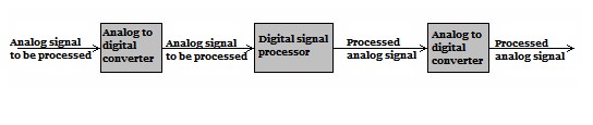
The principle of the digital filter
The digital filter calculates the signal according to the program to achieve the purpose of filtering. By programming the memory of the digital filter, various filtering functions can be realized. For digital filters, adding functions means adding programs, without adding components, not affected by component errors, and processing low-frequency signals without increasing the size of the chip. The digital filtering method can get rid of the problem of analog filters being restricted by components.
The term digital filter appeared in the mid-1960s. Due to the development of electronic computer technology and large-scale integrated circuits, digital filters have been implemented using computer software, or large-scale integrated digital hardware in real-time. The digital filter is a discrete-time system (according to a predetermined algorithm, the input discrete-time signal (corresponding to the digital frequency) is converted into the required output discrete-time signal specific function device).
When using a digital filter to process an analog signal (corresponding to an analog frequency), the input analog signal must be limited, sampled, and converted from analog to digital. The digital filter inputs the digital frequency (2π*f/fs, f is the frequency of the analog signal, fs is the sampling frequency, pay attention to distinguish it from the analog frequency). According to the Nyquist sampling theorem, to avoid the overlap of the spectrum of the sampled signal, the digital frequency should be less than the folding frequency (ws/2=π). The frequency response has a periodic repetition characteristic with 2π intervals and is symmetrical at the folding frequency, that is, ω=π. To obtain an analog signal, the output digital signal processed by the digital filter must undergo digital-to-analog conversion and smoothing. The digital filter has the advantages of high precision, high reliability, programmable change characteristics or multiplexing, and easy integration. Digital filters are widely used in speech signal processing, image signal processing, medical-biological signal processing, and other application fields.
Ⅱ Classification
Digital filters can be divided into one-dimensional, two-dimensional, or multi-dimensional digital filters according to the dimension of the processed signal. The signal processed by the one-dimensional digital filter is a sequence of univariate functions, such as the sampling value of a time function. The signal processed by the two-dimensional or multi-dimensional digital filter is a sequence of two or more variable functions. For example, a two-dimensional image discrete signal is sampled values on plane coordinates.
Digital filter
One-dimensional filter
A one-dimensional filter is an algorithm or device that processes one-dimensional digital signal sequences. The relationship between the output signal sequence y(n) of the linear and time-invariant one-dimensional digital filter and the input signal sequence x(n) is described by a linear, constant-coefficient difference equation:
![]()
Corresponding Z-domain transfer function graph 2 where ar and bk are the digital filter coefficients, Z[y(n)] and Z[x(n)]
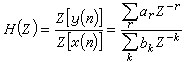
These are the Z transforms of the output and input signal sequences. The inverse Z transformation of the transfer function H(z) is called the unit impulse response of a one-dimensional digital filter, that is, h(n)=Z-1 [H(z)]. The output signal sequence can also be expressed as the discrete convolution of the input signal sequence x(n) and the unit impulse response h(n) of the digital filter
![]()
If the unit impulse response h(n) of the digital filter has only a finite number of non-zero values, it is called a finite impulse response (FIR) digital filter. If the unit impulse response has an infinite number of non-zero values, it is called an infinite impulse response (IIR) digital filter.
The finite impulse response digital filter generally adopts a non-recursive algorithm structure, so it is also called a non-recursive digital filter. Infinite impulse response digital filter can only adopt a recursive algorithm structure, so it is also called a recursive digital filter.
Two-dimensional filter
Two-dimensional filters are algorithms or devices that process two-dimensional digital signal sequences. The relationship between the output y(m,n)and the input x(m,n) of the linear, time-invariant two-dimensional digital filter is described by two-variable linear constant coefficient difference equations:
![]()
The corresponding transfer function is the formula in Figure below, where a b is the filter coefficient, and Z [y (m, n)] and Z [x (m, n)] are the two-dimensional Z transform of the output and input signal sequences, respectively.
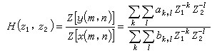
The two-dimensional inverse Z transformation h(m, n)=Z-1 [H(z1, z2] of the transfer function H(z1, z2), called the unit impulse response of the two-dimensional digital filter. The output of y(m,n) can also be expressed as a two-dimensional discrete convolution of the input signal sequence x(m,n) and the unit impulse response h(m,n)
![]()
The two-dimensional digital filter's unit impulse response is also divided into finite impulse response and infinite impulse response. The two-dimensional finite impulse response digital filter is a non-recursive algorithm structure, so it is also called a two-dimensional non-recursive digital filter. The two-dimensional infinite impulse response digital filter is a recursive algorithm structure, so it is also called a two-dimensional recursive digital filter.
Infinite Impulse Response (IIR) Digital Filter
The infinite impulse response IIR digital filter is a digital filter whose response to an input signal of unit impulse is an infinite sequence. It can be divided into a one-dimensional, two-dimensional, or multi-dimensional infinite impulse response digital filter.
Features
1.1 Closed function
The system function of the IIR digital filter can be written as a closed function.
1.2 IIR digital filter adopts the recursive structure
The IIR digital filter adopts a recursive structure, that is, the structure has a feedback loop. The IIR filter operation structure is usually composed of basic operations such as delay, multiplication, and addition. It can be combined into four structural forms: direct, positive, cascade, and parallel, all with feedback loops. Due to the rounding process in the calculation, errors continue to accumulate, and sometimes weak parasitic oscillations are generated.
1.3 With the help of mature analog filters
IIR digital filters can be designed with the help of mature analog filters, such as Butterworth, Chebyshev, and elliptic filters. There are ready-made design data or charts to check, and the design workload is relatively small. The tool requirements are not high. When designing an IIR digital filter, we first write the formula of the analog filter according to the index, and then through a certain transformation, the formula of the analog filter is converted into the formula of the digital filter.
1.4 Need to add phase calibration network
The phase characteristic of the IIR digital filter is not easy to control. When the phase requirement is high, a phase calibration network is required.
Finite Impulse Response (FIR) Digital Filter
The unit impulse response h(n) of a digital filter contains only a finite number of non-zero samples, which is abbreviated as FIR. Its general realization is a non-recursive structure, so it is also called a non-recursive digital filter.
The finite impulse response digital filter has stable characteristics and is easy to design directly according to the impulse response technical conditions; it can achieve symmetrical impulse response while approximating arbitrary amplitude characteristics; it can achieve strict linear phase characteristics. Because it has the above advantages, it has a wide range of applications in data communication and digital communication systems.
The design of the finite impulse response digital filter is mainly to make the value H(e) of the transfer function H(z) on the unit circle approach a given amplitude characteristic. Commonly used design methods are the window function method, frequency sampling method, and equal corrugated machine-aided optimization design method. The finite impulse response digital filter can be implemented in real-time with a multiplier accumulator or a general-purpose digital signal processor (DSP).
 UTMEL
UTMEL
We are the professional distributor of electronic components, providing a large variety of products to save you a lot of time, effort, and cost with our efficient self-customized service. careful order preparation fast delivery service
1.What are digital filters used for?
Digital filters are used for two general purposes: (1) separation of signals that have been combined, and (2) restoration of signals that have been distorted in some way. Analog (electronic) filters can be used for these same tasks; however, digital filters can achieve far superior results.
2.What are the types of digital filters?
There are two fundamental types of digital filters: finite impulse response (FIR) and infinite impulse response (IIR).
3.What are the advantages of digital filters?
Many input signals can be filtered by one digital filter without replacing the hardware. Digital filters have characteristics like linear phase response. The performance of digital filters does not vary with environmental parameters. Unlike analog filters; digital filters are portable.
4.How do you create a digital filter?
The two basic steps for designing a digital filter using Digital Filter Designer are: 1)Define the filter design specifications. This step consists of defining the filter type, design method, and filter order. 2)Define the filter response specifications.
5.What is the disadvantage of digital filters?
Disadvantages of digital filter: It is expensive. The signal bandwidth of the input signal is limited by ADC and DAC. The bandwidth of the digital filter is much lower than an analog filter.
 What is a High-pass Filter?UTMEL10 March 202114550
A high-pass filter is a combination device of capacitors, inductances, and resistors that allow signal components above a certain frequency to pass, while greatly suppressing signal components below that frequency. The high-pass filter only attenuates the frequency components below a given frequency, and allows the frequency components above the cutoff frequency to pass, and there is no phase shift filtering process. Mainly used to eliminate low-frequency noise, also called low-cut filter.
Read More Introduction to Pi FilterUTMEL19 February 202115533
A Pi filter is a type of filter with a two-port, three-terminal block consisting of three elements with two terminals in each element: the first element is connected to the GND terminal via i/p, the second terminals are connected to the terminals from i/p to o/p and the third element is connected to the terminals from o/p to GND. The circuit model is going to be like a 'Pi' symbol. Capacitors and one inductor are the elements used in the circuit.
Read More EMI Filter: Introduction, Functions and ApplicationsUTMEL23 December 202013414
Electromagnetic interference filter, also known as "EMI filter" is an electronic circuit device used to suppress electromagnetic interference, especially noise in power lines or control signal lines. The EMI filter functions as two low-pass filters: one is to attenuate common mode interference, and the other is to attenuate differential mode interference. It is top choice for electronic equipment design engineers to control conducted electromagnetic interference and radiated electromagnetic interference.
Read More SAW Filter: Introduction, Features and ApplicationsUTMEL30 December 202010541
The Surface Acoustic Wave (SAW) filter is a passive band-pass filter made by using the piezoelectric effect and the physical characteristics of surface acoustic wave propagation. Its role is to filter and delay electrical signals. It has the advantages of small size, stable performance, strong overload capacity, low phase distortion, and no need to adjust, so it is used in televisions, video recorders, wireless data transmission systems and other fields.
Read More Introduction to Bandstop FilterUTMEL28 January 20219394
There are numerous filter types, including high-pass filters, low-pass filters, bandpass filters, and filters for bandstops. The high-pass filter only allows frequencies greater than the cut-off frequency, and the low-pass filter allows frequencies smaller than the cut-off frequencies. A specific band of frequencies will be permitted by the bandpass filter and a band stop filter will reject a specific band of frequencies. An overview of the bandstop filter is discussed in this article.
Read More
Subscribe to Utmel !
![SGIHLP73HFB100M81S]() SGIHLP73HFB100M81S
SGIHLP73HFB100M81SVishay
![MGV0605220M-15]() MGV0605220M-15
MGV0605220M-15Laird
![0805WL220JT]() 0805WL220JT
0805WL220JTKYOCERA
![0603WL181JT]() 0603WL181JT
0603WL181JTKYOCERA
![SC75B-151]() SC75B-151
SC75B-151Bel Fuse Inc
![WLCW2520HQG10NPB]() WLCW2520HQG10NPB
WLCW2520HQG10NPBWalsin
![WT32-E-AI5S-aptXC]() WT32-E-AI5S-aptXC
WT32-E-AI5S-aptXCSilicon Laboratories Inc
![WLTF1005Z0B2N4TB]() WLTF1005Z0B2N4TB
WLTF1005Z0B2N4TBWalsin
![PA4390.101HLT]() PA4390.101HLT
PA4390.101HLTPulse
![AISC-0603A-22NJ-T]() AISC-0603A-22NJ-T
AISC-0603A-22NJ-TAbracon
