
 Product
 Brand
Brand Articles
 Tools
Tools
What is FIR Filter?

Introduction to FIR Filters
Catalog
I What is FIR Filter?
FIR (Finite Impulse Response) filter is a finite-length unit impulse response filter, also known as a non-recursive filter, which is the most basic element in a digital signal processing system. It can guarantee arbitrary amplitude-frequency characteristics while having strict linear phase-frequency characteristics, and its unit sampling response is finite, so the filter is a stable system. Therefore, FIR filters are widely used in communication, image processing, pattern recognition, and other fields.
II Working Principle
Before entering the FIR filter, the signal must be converted into an 8-bit digital signal through the A/D device first. Generally, a higher-speed successive approximation A/D converter(SAR ADC) can be used.
Regardless of the multiplication and accumulation method or the distributed algorithm to design the FIR filter, the data output by the filter is a series of sequences. To make it reflect intuitively, it needs to have a digital-to-analog conversion. Therefore, the output of the FIR filter composed of FPGA must be connected to the D/A module.
FPGA has a regular internal logic array and abundant wiring resources, which is especially suitable for digital signal processing. Compared with general-purpose DSP chips dominated by serial operations, it has better parallelism and extendibility. The fast algorithm using FPGA to multiply and accumulate can help us design a high-speed FIR digital filter.
III FIR Filter Implementation
There are several ways of the hardware implementation for FIR filters:
1. Integrated Circuit
It is to use a single-chip general-purpose digital filter integrated circuit. This circuit is simple to use, but it is not easy to fully meet actual needs due to the few specifications for the word length and order. Although multi-chip expansion can be used to meet the requirements, it will increase the volume and power consumption, so it is limited in practical applications.
2. DSP Chips
DSP chips have dedicated digital signal processing functions that can be called, or they can have their own codes to implement FIR functions according to the structure of the chip instruction set.
Because the coefficient calculation and quantization of FIR design are complicated, MATLAB software is generally used as an auxiliary design. And then we can calculate the coefficient of FIR and design and implement the code.
Implementing FIR filters is relatively simple, but because the program is executed sequentially and the speed is limited. Moreover, even the DSP chips of different systems of the same company have different programming instructions, so it has a long development cycle.
3. Programmable FPGA/CPLD
There is also a programmable logic device, FPGA/CPLD. FPGA has a regular array of internal logic blocks and abundant wiring resources. It is particularly suitable for the realization of FIR filters with fine-grained and high-parallel structures. Compared with general-purpose DSP chips dominated by serial operations, it has better parallelism and extendibility
IV FIR Filter Types
The finite impulse response (FIR) filter has the following characteristics:
System function: ![]()
●There are N-1 zeros distributed in the z-plane, where z=0 is the N-1 order pole.
●The unit impulse response h (n) of the system is not zero at a finite number of n values
●The system function H(z) converges at |z|>0, and all the poles are at z=0 (causal system)
●No feedback from output to input, generally non-recursive structure
1. Transverse Type
Difference equation:
![]()

Figure 1. FIR filter Transverse Structure

Figure 2. Transverse Transposed Structure
2. Cascade Type
Decompose H(z) into the product form of the real coefficient second-order factor:
![]()

Figure 3. FIR Filter Cascade Structure (N is an odd number)
When N is an even number, one of them![]() (N-1 zeros)
(N-1 zeros)
Features of cascade type:
●Each basic section controls a pair of zero points, which is convenient to control the transmission zero point of the filter.
●More multiplication operations are required.
3. Frequency Sampling Type
The interpolation formula for N frequency samples H(k) recover H(z):

Subsystem:![]()
It is a comb filter with N-section delay unit, and there are N zero points at equal intervals on the unit circle:
![]() K=0.1...N-1
K=0.1...N-1
Frequency response:

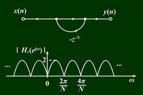
Figure 4. Comb Filter Structure and Frequency Response Amplitude
Subsystem: ![]()
There is a pole on the unit circle: ![]()
Which offset with the kth zero, making the frequency response at this frequency![]() equal to H(k).
equal to H(k).

Figure 5. FIR Filter Frequency Sampling Type Structure
Advantages and Disadvantages of Frequency Sampling Structure
●Adjusting H(k) can effectively adjust the frequency response characteristics.
●If the length of h(n) is the same, the network structure is exactly the same except for the gain H(k) of each branch, which is convenient for standardization and modularization.
●The finite word length effect may cause the poles and zeros to not be completely offset, resulting in system instability.
●The filter coefficients are mostly complex numbers, which increases the amount of complex multiplication and storage.
V Difference between IIR and FIR
1. Both filters are digital filters. According to the difference of impulse response, digital filters are divided into finite impulse response (FIR) filters and infinite impulse response (IIR) filters.
For FIR filters, the impulse response decays to zero in a finite time, and its output depends only on the current and past input signal values. For the IIR filter, the impulse response should theoretically last indefinitely, and its output depends not only on the current and past input signal values, but also on the past signal output values.
2. The impulse response of FIR is limited. Compared with IIR filters, FIR filters have a linear phase and easy to design. On the other hand, to design a filter with the same parameters, FIR requires more parameters than IIR, so the amount of DSP calculations are increased. DSP needs more calculation time, which has an impact on the real-time performance of DSP.
3. In terms of performance, the transfer function of the IIR filter includes two sets of adjustable factors: zero and pole and the only restriction on the pole is to be in the unit circle. Therefore, a lower order can be used to obtain high selectivity, which needs a small number of storage units and calculations and has high efficiency. But this high efficiency comes at the cost of phase nonlinearity. The better the selectivity, the more serious the phase nonlinearity.
The pole of the FIR filter transfer function is fixed at the origin and cannot be moved. It can only change its performance by changing the zero position. Therefore, to achieve high selectivity, a higher order must be used. For the same filter design index, the required order of the FIR filter may be 5-10 times higher than that of the IIR filter. As a result, the cost is higher, and the delay is also relatively large. If the linear phase is required, the IIR filter must add an all-pass network for phase correction, which also greatly increases the order and complexity of the filter. The FIR filter can get a strict linear phase.

Figure 6. Block Diagram of FIR and IIR Filters
4. From the structural point of view, the IIR filter must adopt a recursive structure to configure the poles and ensure that the poles are within the unit circle. Due to the effect of finite word length, the coefficients will be rounded off during the calculation process, causing the pole shift. This situation sometimes causes stability problems and even parasitic oscillations.
On the contrary, as long as the FIR filter adopts a non-recursive structure, there is no stability problem in theory or in actual limited-precision calculations, so the frequency characteristic error is also small. In addition, the FIR filter can use the fast Fourier transform algorithm, and the calculation speed can be much faster under the same order.
In addition, it should also be noted that although the design of IIR filters is simple, they are mainly used to design filters with piecewise constant characteristics, such as low-pass, high-pass, band-pass, and band-stop, which often cannot be separated from the analog filter pattern. The FIR filter is much more flexible, which is especially easy to adapt to some special applications, such as forming a digital differentiator or Hilbert converter, etc., so it has greater adaptability and broad application areas.
From the simple comparison above, we can see that IIR and FIR filters have their own strengths, so they should be selected from various considerations in practical applications.
IIR is more suitable for occasions that are not sensitive to phase requirements, such as language communication so that it can give full play to its cost-effective features. While for image signal processing, in data transmission and other systems that carry information in waveforms, the requirement for the linear phase is higher. If possible, it is better to use FIR filters. Of course, more factors may have to be considered in practical applications.
Regardless of IIR and FIR, the higher the order, the greater the signal delay. At the same time, in the IIR filter, the higher the order, the higher the accuracy requirements for the coefficients, otherwise it is easy to cause the finite word length error to move the pole outside the unit circle. Therefore, we should comprehensively consider the choice of order.
VI FIR Filter Application
With the development of personal audio, the deterioration of sound quality caused by the previous IIR filter processing audio is increasingly being rejected by the market. Although the original IIR is simple, convenient, and has a small calculation amount, its accuracy is not enough. Therefore, in professional audio, many used audio algorithms of FIR 4096, such as Coneq in Latvia, etc.
WFIR filter
To make up for the poor low-frequency processing of FIR at low resolution, some audio algorithms use the opposite WFIR filter. Contrary to FIR, WFIR handles low frequencies better, but can’t work at high frequencies. And the amount of calculation for each work point reaches 6 times the FIR.

Figure 7. Audio FIR Filtering
Advantages of FIR Audio Filter
The advantage of FIR is that the accuracy can be increased indefinitely (under the premise of sufficient computing power), and there is no phase accuracy problem for the IIR filter, which is a relatively high-end solution.
Disadvantage of FIR Audio Filter
1. Because of the high precision adopted, the use of computing resources, memory and power consumption is higher;
2. FIR mainly solves high-frequency problems in other fields. In audio applications, signals below 1Khz often occur, at least FIR 512 can have an effect below 1K.
3. Excessive calculation. Because the width of each processing unit of FIR cannot be adjusted, when we solve the low-frequency problem, the high-frequency will be over-calculated.
New solution
The mixed-use of FIR and IIR, and the newly developed VIR filter for audio.
 UTMEL
UTMEL
We are the professional distributor of electronic components, providing a large variety of products to save you a lot of time, effort, and cost with our efficient self-customized service. careful order preparation fast delivery service
1.What is meant by FIR filter?
In signal processing, a finite impulse response (FIR) filter is a filter whose impulse response (or response to any finite length input) is of finite duration because it settles to zero in finite time. FIR filters can be discrete-time or continuous-time, and digital or analog.
2.What are FIR filters used for?
A finite impulse response (FIR) filter is a filter structure that can be used to implement almost any sort of frequency response digitally. An FIR filter is usually implemented by using a series of delays, multipliers, and adders to create the filter's output.
3.Why and where is FIR filters used?
An FIR filter is used to implement almost any type of digital frequency response. Usually, these filters are designed with a multiplier, adders, and a series of delays to create the output of the filter. The following figure shows the basic FIR filter diagram with N length. The result of delays operates on input samples.
4.How do you implement a FIR filter?
1.Put the input sample into the delay line.
2.Multiply each sample in the delay line by the corresponding coefficient and accumulate the result.
3.Shift the delay line by one sample to make room for the next input sample.
5.What is difference between FIR and IIR filters?
The crucial difference between FIR and IIR filters is that the FIR filter provides an impulse response of a finite period. As against IIR is a type of filter that generates impulse response of infinite duration for a dynamic system.
 What is a High-pass Filter?UTMEL10 March 202114457
A high-pass filter is a combination device of capacitors, inductances, and resistors that allow signal components above a certain frequency to pass, while greatly suppressing signal components below that frequency. The high-pass filter only attenuates the frequency components below a given frequency, and allows the frequency components above the cutoff frequency to pass, and there is no phase shift filtering process. Mainly used to eliminate low-frequency noise, also called low-cut filter.
Read More Introduction to Pi FilterUTMEL19 February 202115409
A Pi filter is a type of filter with a two-port, three-terminal block consisting of three elements with two terminals in each element: the first element is connected to the GND terminal via i/p, the second terminals are connected to the terminals from i/p to o/p and the third element is connected to the terminals from o/p to GND. The circuit model is going to be like a 'Pi' symbol. Capacitors and one inductor are the elements used in the circuit.
Read More EMI Filter: Introduction, Functions and ApplicationsUTMEL23 December 202013366
Electromagnetic interference filter, also known as "EMI filter" is an electronic circuit device used to suppress electromagnetic interference, especially noise in power lines or control signal lines. The EMI filter functions as two low-pass filters: one is to attenuate common mode interference, and the other is to attenuate differential mode interference. It is top choice for electronic equipment design engineers to control conducted electromagnetic interference and radiated electromagnetic interference.
Read More SAW Filter: Introduction, Features and ApplicationsUTMEL30 December 202010453
The Surface Acoustic Wave (SAW) filter is a passive band-pass filter made by using the piezoelectric effect and the physical characteristics of surface acoustic wave propagation. Its role is to filter and delay electrical signals. It has the advantages of small size, stable performance, strong overload capacity, low phase distortion, and no need to adjust, so it is used in televisions, video recorders, wireless data transmission systems and other fields.
Read More Introduction to Bandstop FilterUTMEL28 January 20219292
There are numerous filter types, including high-pass filters, low-pass filters, bandpass filters, and filters for bandstops. The high-pass filter only allows frequencies greater than the cut-off frequency, and the low-pass filter allows frequencies smaller than the cut-off frequencies. A specific band of frequencies will be permitted by the bandpass filter and a band stop filter will reject a specific band of frequencies. An overview of the bandstop filter is discussed in this article.
Read More
Subscribe to Utmel !
![BF1211R]() BF1211R
BF1211RNXP
![N1913A/106]() N1913A/106
N1913A/106Agilent
![NE73435]() NE73435
NE73435CEL
![NIS02D1N8TRF]() NIS02D1N8TRF
NIS02D1N8TRFNippon-Chemi-Con
![UP0.4SA-1R0-R]() UP0.4SA-1R0-R
UP0.4SA-1R0-REaton
![UPC3221GV]() UPC3221GV
UPC3221GVNEC
![UPG2409T6X-1]() UPG2409T6X-1
UPG2409T6X-1CEL
![VTP-01001]() VTP-01001
VTP-01001Premier Magnetics
![WHM30-2525LE]() WHM30-2525LE
WHM30-2525LEToshiba
![WI.232FHSS-250-FCC-CFTC-ST-R]() WI.232FHSS-250-FCC-CFTC-ST-R
WI.232FHSS-250-FCC-CFTC-ST-RLinx Technologies
