
 Product
 Brand
Brand Articles
 Tools
Tools
Manifold Absolute Pressure (MAP) Sensor: Working Principles, Structure, and Types

MAP Sensor - Manifold Absolute Pressure - Explained
Catalog
| |
Ⅰ Introduction
Manifold Absolute Pressure Sensor, referred to as MAP sensor. The Manifold Absolute Pressure (MAP) sensor is a critical component in modern engine management systems, serving as an indirect airflow meter that provides essential data for fuel injection control. This sensor monitors pressure changes within the intake manifold through a vacuum tube connection, converting pressure variations into electrical signals that the Engine Control Unit (ECU) uses to optimize fuel delivery (Ribbens, 2017). The MAP sensor is an indirect airflow meter, and its signal is one of the important signals for the basic fuel injection control of the engine. It is connected to the intake manifold with a vacuum tube. With different engine speed loads, it senses the vacuum change in the intake manifold and then converts the change in the internal resistance of the sensor into a voltage signal for the ECU to correct the fuel injection volume.
In the electronic fuel injection engine, the MAP sensor is used to detect the intake air volume is called the D-type injection system (speed density type). The MAP sensor detects the intake air volume not directly like the intake airflow sensor but uses indirect detection. At the same time, it is also affected by many factors, so there are many differences in the detection and maintenance of the intake airflow from the volume sensor.
Ⅱ Working principle
The MAP sensor detects the absolute pressure of the intake manifold behind the throttle. It detects the absolute pressure change in the manifold according to the engine speed and load, and then converts it into a signal voltage and sends it to the engine control unit (ECU). The ECU controls the basic fuel injection volume according to the signal voltage.
MAP sensors operate by measuring absolute pressure in the intake manifold downstream of the throttle body. The sensor converts pressure variations, which correspond to engine speed and load conditions, into voltage signals for ECU processing. This data is crucial for determining the optimal fuel injection parameters (Bosch, 2019).There are many types of MAP sensors, including varistor type and capacitive type. Because the varistor type has the advantages of fast response time, high detection accuracy, small size, and flexible installation, it is widely used in D-type injection systems.

Figure 1

Figure 2
Figure 1 shows the connection between the varistor type MAP sensor and the computer. Figure 2 is the working principle of the varistor type MAP sensor. The R in Figure 1 is the strain resistance R1, R2, R3, R4 in Figure 2. They form a Wheatstone bridge and are bonded to the silicon diaphragm together. The silicon diaphragm can be deformed under the action of the absolute pressure in the manifold, which causes the resistance value of the strain resistor R to change. The higher the absolute pressure in the manifold, the greater the deformation of the silicon diaphragm and the greater the resistance change of the resistance R. That is, the mechanical change of the silicon diaphragm is converted into an electrical signal, which is then amplified by the integrated circuit and output to the ECU.
Ⅲ Internal structure
The core component of a MAP sensor is a pressure-sensing chip incorporating a Wheatstone bridge circuit integrated onto a deformable silicon diaphragm. This sophisticated design allows for precise pressure measurements through mechanical-to-electrical signal conversion (Wang et al., 2018).The pressure sensor uses a pressure chip for pressure measurement, and the pressure chip integrates a Wheatstone bridge on a silicon diaphragm that can undergo pressure deformation. The pressure chip is the core of the pressure sensor. All major manufacturers of pressure sensors have their own pressure chips. Some are directly produced by sensor manufacturers, some are dedicated chips (ASC) produced by outsourcing, and the other is to directly purchase general-purpose chips from professional chip manufacturers. Chips directly produced by sensor manufacturers or customized ASC chips are generally only used in their own products. Such chips are highly integrated, often using pressure chips, amplifying circuits, signal processing chips, EMC protection circuits, and those used to calibrate sensor output curves. ROM is integrated on a chip, the whole sensor is a chip, and the chip is connected to the PIN pin of the connector through a lead.

Figure 3. The internal structure of the pressure sensor based on MEMS technology
The pressure sensor as shown in Figure 3 integrates other processing circuits except for the sensor chip into the circuit chip, and some pressure sensor manufacturers completely integrate the two into one.
This design and production process of pressure sensors is actually the practical application of MEMS technology (abbreviation of microelectromechanical systems). MEMS is based on 21st-century cutting-edge technology based on micro/nanotechnology. It is the technology of designing, processing, manufacturing, and controlling micro/nano materials. It can integrate mechanical components, optical systems, drive components, electrical control systems, and digital processing systems into a microsystem that is an integral unit. This kind of microelectronic mechanical system can not only collect, process, and send information or instructions, but also take actions according to the acquired information autonomously or according to external instructions. It uses a combination of microelectronics technology and micromachining technology (including silicon body micromachining, silicon surface micromachining, LIGA and wafer bonding, etc.) to produce a variety of excellent performance, low price, miniaturized sensors, execution devices, drives, and microsystems. MEMS emphasizes the use of advanced technology to realize microsystems and highlights the ability of integrated systems.
The pressure sensor is a typical representative of MEMS technology, and another commonly used MEMS technology is the microelectromechanical gyroscope. Several major EMS system suppliers, such as BOSCH, DENSO, CONTI, and other companies, have their own dedicated chips designed with similar structures. Advantages: high integration, small sensor size, the small size of the sensor with small-size connectors, easy to arrange and install. The pressure chip inside the sensor is completely encapsulated in silica gel, which plays the role of corrosion resistance and vibration resistance, which greatly improves the service life of the sensor. Large-scale mass production has low cost, high yield, and excellent performance.
Some other manufacturers of MAP sensors use general-purpose pressure chips and then integrate the pressure chip, EMC protection circuit, and other peripheral circuits and connector PIN pins through the PCR board. As shown in Figure 4, the pressure chip is mounted on the back of the PCB. The PCB is a Double-sided PCB board.
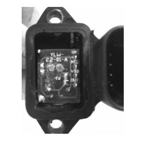
Figure 4. Use PCB board to integrate chips and circuits
Due to the low integration level of this type of pressure sensor, the cost of manufacturing materials is high. The PCB board does not have a fully-sealed package, and the parts are integrated on the PCB board through the traditional soldering process, and there is a risk of virtual soldering. In an environment of high vibration, high temperature, and high humidity, PCB should be protected.
Ⅳ Types of MAP sensor
The MAP sensor converts the pressure of the engine's intake pipe into a corresponding electrical signal. The engine electronic controller calculates the basic fuel injection time and determines the basic ignition advance angle based on this signal. Pressure sensors come in many forms. According to the principle of signal generation, they can be divided into piezoelectric, semiconductor varistor, capacitive, differential transformer, and surface elastic wave types.
Semiconductor Varistor MAP Sensor
Features rapid response time
High detection accuracy
Compact design
Flexible installation options
Capacitive MAP Sensor
Utilizes capacitive sensing technology
Offers stable pressure measurements
Enhanced durability
1. Semiconductor varistor MAP sensor
(1) Measuring principle of semiconductor varistor pressure sensor
The semiconductor varistor pressure sensor uses the piezoresistive effect of semiconductors to convert pressure into a corresponding voltage signal, and its principle is shown in Figure 5.
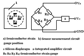
Figure 5. Measuring principle of semiconductor varistor pressure sensor
The semiconductor strain gauge is a sensitive element whose resistance value changes correspondingly when under tension or pressure. Attach the strain gauges to the silicon diaphragm and connect them to a Wheatstone bridge. When the silicon diaphragm is deformed by force, each strain gauge is pulled or compressed and its resistance changes and the bridge will have a corresponding voltage output.
(2) Structure of varistor MAP sensor
The composition of the semiconductor varistor MAP sensor is shown in Figure 6. There is a silicon diaphragm in the pressure conversion element of the sensor, and the pressure and deformation of the silicon diaphragm will generate a corresponding voltage signal. One side of the silicon diaphragm is vacuum, and the other side introduces the pressure of the intake pipe. When the pressure in the intake pipe changes, the deformation of the silicon diaphragm will change accordingly, and a voltage signal corresponding to the intake pressure is generated. The greater the intake pressure, the greater the deformation of the silicon diaphragm, and the greater the output pressure of the sensor.

Figure 6. Structure of varistor MAP sensor
The semiconductor varistor MAP sensor has good linearity and has the advantages of small structure size, high precision and good response characteristics.
2. Capacitive MAP sensor
(1) Measuring principle of a capacitive MAP sensor
The capacitive pressure sensor uses a diaphragm to form a pressure-sensitive element with a variable capacitance. When the diaphragm is deformed by force, its capacitance changes accordingly. The sensor measuring circuit converts the capacitance change corresponding to the pressure into a corresponding electrical signal. Capacitive pressure sensor measurement circuits mainly have two types: frequency detection and voltage detection, as shown in Figure 7.
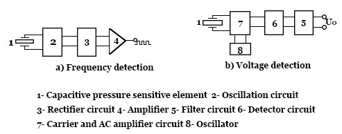
Figure 7. Measuring principle of the capacitive MAP sensor
1) Frequency detection type: The oscillating frequency of the oscillating circuit changes with the change of the capacitance value of the pressure sensitive element, and the pulse signal whose frequency corresponds to the pressure is output after rectification and amplification.
2) Voltage detection type: the change of the capacitance value of the pressure sensitive element is modulated by the carrier and AC amplifier circuit, demodulated by the detector circuit, and filtered by the filter circuit to output a voltage signal corresponding to the pressure change.
(2) The structure of the capacitive MAP sensor
The schematic diagram of the capacitive MAP sensor is shown in Figure 8. The aluminum oxide diaphragm and the hollow insulating medium form a capacitive pressure sensitive element with a vacuum inside, which is connected to the sensor hybrid integrated circuit. After the sensor introduces the pressure of the intake pipe, the aluminum oxide diaphragm deforms under the action of the intake pressure, causing its capacitance value to change. After processing by the hybrid integrated circuit, it outputs an electrical signal corresponding to the change in the intake pressure.

Figure 8. Structure of capacitive MAP sensor
Compared with the intake airflow sensor that plays the same role, the MAP sensor has no interference to the air intake, and the installation position is flexible (the MAP sensor can be installed far away from the engine intake pipe using the guidance of the vacuum tube). Therefore, the use of MAP sensors in modern engine electronic control systems is increasing.
Ⅴ Output characteristics
The sensor output typically follows a linear relationship between pressure and voltage, with specific calibration curves depending on the manufacturer and application requirements (Reif, 2021).When the engine is working, as the throttle opening changes, the vacuum, absolute pressure and output signal characteristic curve in the intake manifold are all changing.
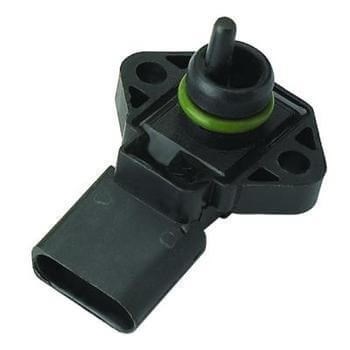
Figure 9. MAP sensor
The D-type injection system detects the absolute pressure in the intake manifold behind the throttle. The rear of the throttle reflects both the vacuum degree and the absolute pressure. Therefore, some people think that the vacuum degree and absolute pressure are the same concepts, but this understanding is one-sided. Under the condition of constant atmospheric pressure (standard atmospheric pressure is 101.3kPa), the higher the vacuum in the manifold, the lower the absolute pressure in the manifold. The vacuum is equal to the atmospheric pressure minus the absolute pressure in the manifold. The higher the absolute pressure in the manifold, the lower the vacuum in the manifold. The absolute pressure in the manifold is equal to the atmospheric pressure outside the manifold minus the vacuum. That is, atmospheric pressure is equal to the sum of vacuum and absolute pressure. After understanding the relationship between atmospheric pressure, vacuum, and absolute pressure, the output characteristics of the MAP sensor are clear.
During engine operation, the smaller the throttle opening, the greater the vacuum of the intake manifold, the smaller the absolute pressure in the manifold, and the smaller the output signal voltage. The greater the throttle opening, the smaller the vacuum of the intake manifold, the greater the absolute pressure in the manifold, and the greater the output signal voltage. The output signal voltage is inversely proportional to the vacuum in the manifold and proportional to the absolute pressure in the manifold.
References:
Bosch, R. (2019). Automotive Handbook (10th ed.). Wiley.
https://www.wiley.com/en-us/Bosch+Automotive+Handbook%2C+10th+Edition-p-9781119530824
Reif, K. (2021). Fundamentals of Automotive and Engine Technology. Springer.
https://www.springer.com/gp/book/9783658039721
Ribbens, W. B. (2017). Understanding Automotive Electronics: An Engineering Perspective (8th ed.). Butterworth-Heinemann.
https://www.elsevier.com/books/understanding-automotive-electronics/ribbens/978-0-12-810434-7
Wang, Y., Li, Y., & Zhang, L. (2018). Modern Automotive Sensors: Technology and Applications. IEEE Sensors Journal, 18(12), 5271-5283.
https://ieeexplore.ieee.org/document/8344479
Related Articles:
 UTMEL
UTMEL
We are the professional distributor of electronic components, providing a large variety of products to save you a lot of time, effort, and cost with our efficient self-customized service. careful order preparation fast delivery service
1.What does a manifold absolute pressure sensor do?
The sensor provides instant manifold pressure information to the engine's electronic control unit. The data is used to calculate air density and determine the engine's air mass flow rate, which in turn determines the required fuel delivery for perfect combustion.
2.What happens when the MAP sensor goes bad?
If the MAP sensor goes bad, the ECM can't accurately calculate engine load, which means the air-fuel ratio will become either too rich (more fuel) or too lean (less fuel). This leads to excessive fuel consumption, poor fuel economy, and possibly detonation. Lack of Power.
3.How much is a manifold absolute pressure sensor?
This sensor is integral to keeping your engine safe and making sure your car runs smoothly. You will pay between $130 and $200 for map sensor replacement. The labor costs on that should be about $14-$25, while part should run between $110 and $180.
4.How do you test a manifold absolute pressure sensor?
Checking for reference voltage: Turn the ignition key to the On position but don't start the engine. This will allow the computer to supply a reference voltage to the MAP sensor. Set your multimeter to about 10V on the direct current (DCV) scale. Backprobe the reference wire at the connector. ... Turn off the ignition key.
5.Can you drive with a bad map sensor?
It is not advisable to drive your vehicle with the MAP (manifold absolute pressure) sensor disconnected. With the MAP sensor disconnected, the fuel delivery will be excessive and could cause harm to the engine and exhaust system (catalytic converters).
 The Key Role of Electronic Components in IoT DevicesUTMEL01 September 20235599
The article discusses the pivotal role of electronic components in Internet of Things (IoT) devices. IoT devices work by capturing real-world data using sensors, processing it through a microcontroller, and then sending it to the cloud for further analysis.
Read More How to Identify the Perfect Proximity Sensor for Your ApplicationUTMEL19 July 20251510
Find the best proximity sensors for your project by evaluating material, sensing range, environment, and system needs to ensure optimal performance and reliability.
Read More Trusted Vibration Sensors for Homeowners and Industry ProfessionalsUTMEL17 July 20251190
Compare top vibration sensors for home and industrial use. Find trusted options for security, predictive maintenance, and equipment protection.
Read More Wiring and Mounting Photoelectric Sensors in 2025UTMEL15 July 20251411
Wire and mount photoelectric sensors in 2025 with step-by-step safety, wiring, and alignment tips for reliable installation and optimal sensor performance.
Read More Essential Tips for Picking the Best Gas SensorUTMEL15 July 20252730
Find out how to select gas sensors by matching target gases, environment, and compliance needs for reliable and accurate gas detection in any setting.
Read More
Subscribe to Utmel !
