
 Product
 Brand
Brand Articles
 Tools
Tools
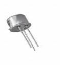
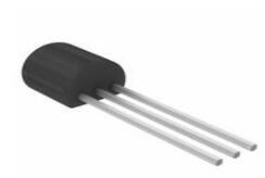
BFS20 BJT Transistor: SOT23, BFS20 Datasheet, Pinout


TRANS NPN 20V 0.025A SOT23
BFS20 is NPN medium frequency transistor. This article will cover its pinout, datasheet, feature and more details about BFS20.
BFS20 Pinout

BFS20 Pinout
| Pin | Description |
| 1 | base |
| 2 | emitter |
| 3 | collector |
BFS20 CAD Model
Symbol

BFS20 Symbol
Footprint

BFS20 Footprint
3D Model

BFS20 3D Model
BFS20 Description
BFS20 is an NPN medium frequency transistor in a SOT23 plastic package.
BFS20 Feature
• IC(max) = 25 mA
• VCEO(max) = 20 V
• Very low feedback capacitance (typ. 350 fF).
BFS20 Application
• IF and VHF thick and thin-film circuit applications.
BFS20 Alternative
BFS20 Package

BFS20 Package
BFS20 Manufacturer
Nexperia is a dedicated global leader in Discretes, Logic and MOSFETs devices. This new company became independent at the beginning of 2017. Focused on efficiency, Nexperia produces consistently reliable semiconductor components at a high volume: 85 billion annually. The company’s extensive portfolio meets the stringent standards set by the Automotive industry. And industry-leading small packages, produced in their own manufacturing facilities, combine power and thermal efficiency with best-in-class quality levels. Built on over half a century of expertise, Nexperia has 11,000 employees across Asia, Europe and the U.S. supporting
Specifications
- TypeParameter
- Factory Lead Time4 Weeks
- Contact Plating
Contact plating (finish) provides corrosion protection for base metals and optimizes the mechanical and electrical properties of the contact interfaces.
Tin - Mount
In electronic components, the term "Mount" typically refers to the method or process of physically attaching or fixing a component onto a circuit board or other electronic device. This can involve soldering, adhesive bonding, or other techniques to secure the component in place. The mounting process is crucial for ensuring proper electrical connections and mechanical stability within the electronic system. Different components may have specific mounting requirements based on their size, shape, and function, and manufacturers provide guidelines for proper mounting procedures to ensure optimal performance and reliability of the electronic device.
Surface Mount - Mounting Type
The "Mounting Type" in electronic components refers to the method used to attach or connect a component to a circuit board or other substrate, such as through-hole, surface-mount, or panel mount.
Surface Mount - Package / Case
refers to the protective housing that encases an electronic component, providing mechanical support, electrical connections, and thermal management.
TO-236-3, SC-59, SOT-23-3 - Number of Pins3
- Transistor Element Material
The "Transistor Element Material" parameter in electronic components refers to the material used to construct the transistor within the component. Transistors are semiconductor devices that amplify or switch electronic signals and are a fundamental building block in electronic circuits. The material used for the transistor element can significantly impact the performance and characteristics of the component. Common materials used for transistor elements include silicon, germanium, and gallium arsenide, each with its own unique properties and suitability for different applications. The choice of transistor element material is crucial in designing electronic components to meet specific performance requirements such as speed, power efficiency, and temperature tolerance.
SILICON - Collector-Emitter Breakdown Voltage20V
- Number of Elements1
- Operating Temperature
The operating temperature is the range of ambient temperature within which a power supply, or any other electrical equipment, operate in. This ranges from a minimum operating temperature, to a peak or maximum operating temperature, outside which, the power supply may fail.
150°C TJ - Packaging
Semiconductor package is a carrier / shell used to contain and cover one or more semiconductor components or integrated circuits. The material of the shell can be metal, plastic, glass or ceramic.
Tape & Reel (TR) - Series
In electronic components, the "Series" refers to a group of products that share similar characteristics, designs, or functionalities, often produced by the same manufacturer. These components within a series typically have common specifications but may vary in terms of voltage, power, or packaging to meet different application needs. The series name helps identify and differentiate between various product lines within a manufacturer's catalog.
Automotive, AEC-Q101 - Published2009
- JESD-609 Code
The "JESD-609 Code" in electronic components refers to a standardized marking code that indicates the lead-free solder composition and finish of electronic components for compliance with environmental regulations.
e3 - Part Status
Parts can have many statuses as they progress through the configuration, analysis, review, and approval stages.
Active - Moisture Sensitivity Level (MSL)
Moisture Sensitivity Level (MSL) is a standardized rating that indicates the susceptibility of electronic components, particularly semiconductors, to moisture-induced damage during storage and the soldering process, defining the allowable exposure time to ambient conditions before they require special handling or baking to prevent failures
1 (Unlimited) - Number of Terminations3
- ECCN Code
An ECCN (Export Control Classification Number) is an alphanumeric code used by the U.S. Bureau of Industry and Security to identify and categorize electronic components and other dual-use items that may require an export license based on their technical characteristics and potential for military use.
EAR99 - Max Power Dissipation
The maximum power that the MOSFET can dissipate continuously under the specified thermal conditions.
250mW - Terminal Position
In electronic components, the term "Terminal Position" refers to the physical location of the connection points on the component where external electrical connections can be made. These connection points, known as terminals, are typically used to attach wires, leads, or other components to the main body of the electronic component. The terminal position is important for ensuring proper connectivity and functionality of the component within a circuit. It is often specified in technical datasheets or component specifications to help designers and engineers understand how to properly integrate the component into their circuit designs.
DUAL - Terminal Form
Occurring at or forming the end of a series, succession, or the like; closing; concluding.
GULL WING - Peak Reflow Temperature (Cel)
Peak Reflow Temperature (Cel) is a parameter that specifies the maximum temperature at which an electronic component can be exposed during the reflow soldering process. Reflow soldering is a common method used to attach electronic components to a circuit board. The Peak Reflow Temperature is crucial because it ensures that the component is not damaged or degraded during the soldering process. Exceeding the specified Peak Reflow Temperature can lead to issues such as component failure, reduced performance, or even permanent damage to the component. It is important for manufacturers and assemblers to adhere to the recommended Peak Reflow Temperature to ensure the reliability and functionality of the electronic components.
260 - Frequency
In electronic components, the parameter "Frequency" refers to the rate at which a signal oscillates or cycles within a given period of time. It is typically measured in Hertz (Hz) and represents how many times a signal completes a full cycle in one second. Frequency is a crucial aspect in electronic components as it determines the behavior and performance of various devices such as oscillators, filters, and communication systems. Understanding the frequency characteristics of components is essential for designing and analyzing electronic circuits to ensure proper functionality and compatibility with other components in a system.
450MHz - Time@Peak Reflow Temperature-Max (s)
Time@Peak Reflow Temperature-Max (s) refers to the maximum duration that an electronic component can be exposed to the peak reflow temperature during the soldering process, which is crucial for ensuring reliable solder joint formation without damaging the component.
40 - Base Part Number
The "Base Part Number" (BPN) in electronic components serves a similar purpose to the "Base Product Number." It refers to the primary identifier for a component that captures the essential characteristics shared by a group of similar components. The BPN provides a fundamental way to reference a family or series of components without specifying all the variations and specific details.
BFS20 - Pin Count
a count of all of the component leads (or pins)
3 - Element Configuration
The distribution of electrons of an atom or molecule (or other physical structure) in atomic or molecular orbitals.
Single - Power Dissipation
the process by which an electronic or electrical device produces heat (energy loss or waste) as an undesirable derivative of its primary action.
250mW - Gain Bandwidth Product
The gain–bandwidth product (designated as GBWP, GBW, GBP, or GB) for an amplifier is the product of the amplifier's bandwidth and the gain at which the bandwidth is measured.
450MHz - Polarity/Channel Type
In electronic components, the parameter "Polarity/Channel Type" refers to the characteristic that determines the direction of current flow or the type of signal that can be accommodated by the component. For components like diodes and transistors, polarity indicates the direction in which current can flow through the component, such as forward bias or reverse bias for diodes. For components like MOSFETs or JFETs, the channel type refers to whether the component is an N-channel or P-channel device, which determines the type of charge carriers that carry current through the component. Understanding the polarity or channel type of a component is crucial for proper circuit design and ensuring that the component is connected correctly to achieve the desired functionality.
NPN - Transistor Type
Transistor type refers to the classification of transistors based on their operation and construction. The two primary types are bipolar junction transistors (BJTs) and field-effect transistors (FETs). BJTs use current to control the flow of current, while FETs utilize voltage to control current flow. Each type has its own subtypes, such as NPN and PNP for BJTs, and MOSFETs and JFETs for FETs, impacting their applications and characteristics in electronic circuits.
NPN - Collector Emitter Voltage (VCEO)
Collector-Emitter Voltage (VCEO) is a key parameter in electronic components, particularly in transistors. It refers to the maximum voltage that can be applied between the collector and emitter terminals of a transistor while the base terminal is open or not conducting. Exceeding this voltage limit can lead to breakdown and potential damage to the transistor. VCEO is crucial for ensuring the safe and reliable operation of the transistor within its specified limits. Designers must carefully consider VCEO when selecting transistors for a circuit to prevent overvoltage conditions that could compromise the performance and longevity of the component.
20V - Max Collector Current
Max Collector Current is a parameter used to specify the maximum amount of current that can safely flow through the collector terminal of a transistor or other electronic component without causing damage. It is typically expressed in units of amperes (A) and is an important consideration when designing circuits to ensure that the component operates within its safe operating limits. Exceeding the specified max collector current can lead to overheating, degradation of performance, or even permanent damage to the component. Designers must carefully consider this parameter when selecting components and designing circuits to ensure reliable and safe operation.
25mA - DC Current Gain (hFE) (Min) @ Ic, Vce
The parameter "DC Current Gain (hFE) (Min) @ Ic, Vce" in electronic components refers to the minimum value of the DC current gain, denoted as hFE, under specific operating conditions of collector current (Ic) and collector-emitter voltage (Vce). The DC current gain hFE represents the ratio of the collector current to the base current in a bipolar junction transistor (BJT), indicating the amplification capability of the transistor. The minimum hFE value at a given Ic and Vce helps determine the transistor's performance and efficiency in amplifying signals within a circuit. Designers use this parameter to ensure proper transistor selection and performance in various electronic applications.
40 @ 7mA 10V - Current - Collector Cutoff (Max)
The parameter "Current - Collector Cutoff (Max)" refers to the maximum current at which a transistor or other electronic component will cease to conduct current between the collector and emitter terminals. This parameter is important in determining the maximum current that can flow through the component when it is in the cutoff state. Exceeding this maximum cutoff current can lead to malfunction or damage of the component. It is typically specified in the component's datasheet and is crucial for proper circuit design and operation.
100nA ICBO - Transition Frequency
Transition Frequency in electronic components refers to the frequency at which a device can transition from one state to another, typically defining the upper limit of its operating frequency. It is a critical parameter in determining the speed and performance of active components like transistors and integrated circuits. This frequency is influenced by factors such as capacitance, resistance, and the inherent characteristics of the materials used in the component's construction. Understanding transition frequency is essential for optimizing circuit designs and ensuring reliable signal processing in various applications.
450MHz - Max Breakdown Voltage
The "Max Breakdown Voltage" of an electronic component refers to the maximum voltage that the component can withstand across its terminals before it breaks down and allows current to flow uncontrollably. This parameter is crucial in determining the operating limits and safety margins of the component in a circuit. Exceeding the maximum breakdown voltage can lead to permanent damage or failure of the component. It is typically specified by the manufacturer in datasheets to guide engineers and designers in selecting the appropriate components for their applications.
20V - Collector Base Voltage (VCBO)
Collector Base Voltage (VCBO) is the maximum allowable voltage that can be applied between the collector and base terminals of a bipolar junction transistor when the emitter is open. It is a critical parameter that determines the voltage rating of the transistor and helps prevent breakdown in the collector-base junction. Exceeding this voltage can lead to permanent damage or failure of the component.
30V - Emitter Base Voltage (VEBO)
Emitter Base Voltage (VEBO) is a parameter used in electronic components, particularly in transistors. It refers to the maximum voltage that can be applied between the emitter and base terminals of a transistor without causing damage to the device. Exceeding this voltage limit can lead to breakdown of the transistor and potential failure. VEBO is an important specification to consider when designing circuits to ensure the proper operation and reliability of the components. It is typically provided in the datasheet of the transistor and should be carefully observed to prevent any potential damage during operation.
4V - Continuous Collector Current
Continuous Collector Current is the maximum amount of current that a transistor can continuously carry through its collector terminal without overheating or being damaged. This parameter is crucial for designing circuits as it determines the suitability of a transistor for specific applications. Exceeding this value can lead to reduced performance or failure of the component. It is typically specified in amperes (A) and varies based on the transistor's construction and cooling conditions.
25mA - Radiation Hardening
Radiation hardening is the process of making electronic components and circuits resistant to damage or malfunction caused by high levels of ionizing radiation, especially for environments in outer space (especially beyond the low Earth orbit), around nuclear reactors and particle accelerators, or during nuclear accidents or nuclear warfare.
No - RoHS Status
RoHS means “Restriction of Certain Hazardous Substances” in the “Hazardous Substances Directive” in electrical and electronic equipment.
ROHS3 Compliant
Parts with Similar Specs
- ImagePart NumberManufacturerMountPackage / CaseCollector Emitter Breakdown VoltageMax Collector CurrentTransition FrequencyMax Power DissipationPower DissipationMounting TypeView Compare
![BFS20,235]()
BFS20,235
Surface Mount
TO-236-3, SC-59, SOT-23-3
20 V
25 mA
450 MHz
250 mW
250 mW
Surface Mount
![BFR94A,215]()
Surface Mount
TO-236-3, SC-59, SOT-23-3
20 V
30 mA
150 MHz
200 mW
-
Surface Mount
![MSC2295-CT1]()
Surface Mount
TO-236-3, SC-59, SOT-23-3
20 V
30 mA
150 MHz
200 mW
-
Surface Mount
![MSC2295-BT1G]()
Surface Mount
TO-236-3, SC-59, SOT-23-3
20 V
30 mA
150 MHz
200 mW
-
Surface Mount
![MSC2295-CT1G]()
-
TO-236-3, SC-59, SOT-23-3
-
-
-
-
-
Surface Mount


Datasheet PDF
- PCN Packaging :
- Datasheets :
- PCN Design/Specification :
- RohsStatement :
Trend Analysis
What is an NPN medium frequency transistor in a SOT23 plastic package?
BFS20.
What is the function of BJT?
As with all transistors, the basic function of a BJT is typically to function as a switch or to amplify, filter, and rectify power. Bipolar transistors are current-controlled and operated devices, meaning that a much smaller base current causes a larger current to flow from emitter to collector.
What is BJT and its working?
A Bipolar Junction Transistor (also known as a BJT or BJT Transistor) is a three-terminal semiconductor device consisting of two p-n junctions which are able to amplify or magnify a signal. It is a current controlled device. The three terminals of the BJT are the base, the collector and the emitter.
 2N3439 Transistor: Datasheet, Equivalent, Pinout
09 December 20212400
 TPS40304DRCR Synchronous Buck Controller: Datasheet, Circuit, Pinout
23 March 2022667
 A Comprehensive Guide to LTC7851EUHH-1#TRPBF DC-DC Switching Controller
06 March 2024122
 1N34A Diode: Datasheet, Circuit and Alternatives
27 August 202110646
 AD8676 2.8 nV/√Hz Low-Noise Op-Amp: Precision Datasheet and Design Analysis
16 March 2026116
 NRF24L01P Transceiver: Datasheet, Pinout and Applications
14 August 20213578
 J108 JFET N Channel Transistor: J108 Transistor, Price, Datasheet
11 January 20223772
 STM8S105K4T6C Microcontroller: Features, Specifications and Applications
10 June 2025190
 Shenzhen: This Year Will Focus on Promoting SMIC and CR Micro 12-inch Project
13 April 20226831
 Huawei's Mysterious Advanced Chip in New Mate 60 Pro Smartphone Sparks Speculation Amid US Sanctions
01 September 20233807
 Hybrid Sources Powered Electric Vehicles - Part 1
08 March 20233418
 What is Spectrum Analyzer?
17 December 20215173
 Inverter Introduction: Structures, Working Principles and Features
18 February 202237087
 What is a Synchronous Motor?
16 March 20216980
 Huawei's Sensor Layout
24 March 20222648
 The Complete Guide to 12 Gauge Wire: Ampacity, Load Limits, and NEC Rules
14 May 2026391
Nexperia USA Inc.
In Stock: 321400
Minimum: 1 Multiples: 1
Qty
Unit Price
Ext Price
1
$0.240177
$0.24
10
$0.226582
$2.27
100
$0.213757
$21.38
500
$0.201657
$100.83
1000
$0.190243
$190.24
Not the price you want? Send RFQ Now and we'll contact you ASAP.
Inquire for More Quantity
![PMBT3904,215]() PMBT3904,215
PMBT3904,215Nexperia USA Inc.
![BC857C,215]() BC857C,215
BC857C,215Nexperia USA Inc.
![BC817-40,215]() BC817-40,215
BC817-40,215Nexperia USA Inc.
![BC807-40,215]() BC807-40,215
BC807-40,215Nexperia USA Inc.
![BC846B,215]() BC846B,215
BC846B,215Nexperia USA Inc.
![PMBT2222A,215]() PMBT2222A,215
PMBT2222A,215Nexperia USA Inc.
![PMBT2907A,215]() PMBT2907A,215
PMBT2907A,215Nexperia USA Inc.
![BC807-25,215]() BC807-25,215
BC807-25,215Nexperia USA Inc.
![PBSS4350Z,135]() PBSS4350Z,135
PBSS4350Z,135Nexperia USA Inc.
![BC847,215]() BC847,215
BC847,215Nexperia USA Inc.
