
 Product
 Brand
Brand Articles
 Tools
Tools
AP2112K-3.3TRG1: 600mA LDO Voltage Regulator Review & Applications


Enable Fixed PMIC SC-74A, SOT-753
Diodes Incorporated AP2112K-3.3TRG1 offers reliable 3.3V output, easy PCB integration, and efficient performance for demanding electronics projects.
Product Introduction
Designers often call the diodes incorporated ap2112k-3.3trg1 a game changer. One user said, “This regulator never lets my project down.” Engineers appreciate its blend of reliability and efficiency. Even with only partial shipment records available, the component has built a strong reputation in the electronics community. Practical feedback highlights its stable performance and easy integration into demanding designs.
User Experiences
Integration
Engineers often choose the diodes incorporated ap2112k-3.3trg1 for its easy integration into many designs. The compact SOT-25 package fits well on crowded pcb layouts. Designers appreciate the enable function, which allows them to control the output with a simple logic signal. This feature helps save power in battery-powered sensor projects. The device supports a wide input voltage range, making it suitable for different power sources. Many users report that the regulator drops into an integrated pcb without major layout changes. The small footprint leaves more space for other components, such as microcontrollers or sensor modules.
Tip: Place the input and output capacitors close to the regulator pins on the pcb. This practice improves output stability and reduces noise.
Reliability
The ap2112k-3.3trg1 shows strong reliability in various applications. Users often mention the stable output voltage, even when the load changes quickly. The regulator maintains output stability in sensor circuits that require precise voltage control. In battery-powered devices, the low dropout voltage ensures the output stays close to 3.3V until the battery nears depletion. Some users have noticed rare issues, such as no output under certain switching conditions. Careful pcb layout and proper capacitor selection usually solve these problems. The device’s thermal performance also supports stability, even in tight spaces where heat can build up.
Key reliability highlights:
Consistent output voltage for sensitive sensor applications
Maintains output stability during rapid load changes
Handles moderate heat on dense pcb layouts
User Feedback
Community feedback for the ap2112k-3.3trg1 remains positive. Many engineers use it in sensor nodes, wireless modules, and portable devices. The regulator’s low quiescent current helps extend battery life in sensor-based projects. Users praise the clean output, which prevents sensor errors caused by voltage noise. The compact package fits well in space-constrained designs, such as wearables and IoT devices. Some hobbyists share that the regulator works well with both analog and digital sensor circuits. The device’s output stability gives designers confidence in long-term projects.
| Application | Benefit | User Comment Example |
|---|---|---|
| Sensor Node | Stable output voltage | "No drift in sensor readings." |
| Wearable Device | Fits small pcb, low heat | "Perfect for my fitness tracker." |
| IoT Module | Reliable output, easy to enable | "Simple to control with MCU pin." |
| Battery Gadget | Maintains output stability | "Runs sensors until battery dies." |
Note: For best results, always check the output with a multimeter after soldering the regulator to the pcb. This step ensures output stability before connecting sensitive sensor circuits.
Performance
Voltage Accuracy
The AP2112K-3.3TRG1 delivers precise voltage regulation in demanding applications. Engineers rely on its fixed 3.3V output, which maintains accuracy within ±1.5%. This level of voltage control ensures sensitive circuits receive the correct output, even when the load changes. The device features a typical load regulation of 0.2% per ampere, which means the output voltage remains stable as current demand shifts. Fast loop response further enhances output stability, preventing voltage dips or spikes during rapid load transitions.
The following table summarizes key technical parameters that contribute to voltage accuracy and output stability:
| Parameter | Value |
|---|---|
| Output Voltage | 3.3 V |
| Maximum Output Current | 600 mA |
| Typical Dropout Voltage | 250 mV |
| Maximum Dropout Voltage | 400 mV |
| Load Regulation | 0.2 %/A |
| Typical PSRR | 65 dB |
| Quiescent Current | 55 µA |
| Operating Temperature | -40°C to +85°C |
Accuracy measures how closely the output voltage matches the specified 3.3V.
Protection features, such as overcurrent and overtemperature protection, improve output stability under varying load conditions.
Designers often select this regulator for projects that require consistent voltage and reliable output stability. The device’s performance in maintaining output voltage under different loads makes it a favorite in sensor and microcontroller circuits.
Efficiency
Efficiency plays a critical role in battery-powered and portable devices. The AP2112K-3.3TRG1 achieves high efficiency through its low dropout voltage and minimal quiescent current. At a typical load, the dropout voltage measures around 0.2V, with a maximum of 0.4V at 600mA. This low dropout voltage allows the output to stay close to the input voltage, reducing wasted energy and heat.
The following table highlights efficiency-related parameters:
| Parameter | Value | Condition/Notes |
|---|---|---|
| Quiescent Current (Iq) | 0.3mA (typical) | Typical value |
| Dropout Voltage | 0.2V (typical) | Typical value |
| Dropout Voltage | 0.4V (max) | Max at 600mA load |
| Output Current | 500mA | Typical operating load |
| PSRR | 70dB (typical) | Frequency 100Hz-1kHz |
Low quiescent current means the regulator draws little power when the load is light or idle. This feature extends battery life in devices that spend much time in standby mode. The AP2112K-3.3TRG1’s output voltage remains stable even as the battery voltage drops, which is essential for consistent device operation.
When compared to other regulators, the AP2112K-3.3TRG1 stands out for its low dropout voltage at higher output currents. For example, the LD1117S33CTR has a dropout voltage of about 1.0V at 950mA, while the AP2112K-3.3TRG1 achieves 0.4V at 600mA. This advantage means less energy is lost as heat, and the output voltage stays closer to the input.
Thermal Aspects
Thermal performance affects both reliability and output stability. The AP2112K-3.3TRG1 operates reliably within an ambient temperature range from -40°C to +85°C. This wide range allows the device to maintain output voltage and stability in harsh environments. The compact SOT-25 package helps dissipate heat efficiently, even in dense PCB layouts.
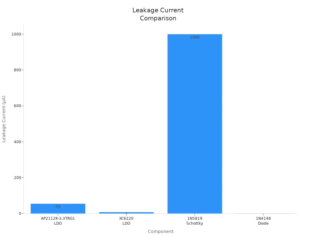
Designers must consider the trade-offs between efficiency and battery life. The AP2112K-3.3TRG1 has a quiescent current of about 55 µA, which is higher than some ultra-low-power LDOs like the XC6220 (8 µA). This higher leakage can reduce battery life during long standby periods. Schottky diodes, such as the 1N5819, offer lower forward voltage drop but suffer from higher reverse leakage, which can also impact battery life.
Note: The AP2112K-3.3TRG1’s maximum recommended ambient temperature is +85°C. Staying within this limit ensures reliable output and long-term stability.
Diodes Incorporated AP2112K-3.3TRG1 Comparison
Competing Regulators
Engineers often compare the diodes incorporated ap2112k-3.3trg1 to other low dropout (LDO) regulators like the LD1117, MIC5205, and XC6220. Each regulator has unique features, but the diodes incorporated ap2112k-3.3trg1 stands out for its compact SOT-25 package and reliable performance on crowded pcb layouts. The LD1117 offers higher current but needs more pcb space and generates more heat. The MIC5205 uses less power in standby but cannot handle as much current. The XC6220 has lower quiescent current, which helps battery life, but its maximum output current is lower.
| Regulator | Max Output (mA) | Dropout Voltage | Quiescent Current | Package Size | pcb Integration |
|---|---|---|---|---|---|
| AP2112K-3.3TRG1 | 600 | 0.25V | 55 µA | SOT-25 | Easy |
| LD1117 | 800 | 1.0V | 5 mA | SOT-223 | Needs space |
| MIC5205 | 150 | 0.35V | 90 µA | SOT-23-5 | Simple |
| XC6220 | 700 | 0.2V | 8 µA | SOT-25 | Easy |
Note: Engineers should match the regulator to the pcb design and current needs of the project.
Pros and Cons
The diodes incorporated ap2112k-3.3trg1 offers several advantages for modern pcb designs:
Pros:
Fast response to load changes keeps output stable.
Compact SOT-25 package saves pcb space.
Enable pin allows easy power control on the pcb.
Low dropout voltage supports longer battery use.
Reliable operation in dense pcb layouts.
Cons:
Quiescent current is higher than some ultra-low-power LDOs, which can affect battery life in always-on pcb circuits.
Careful pcb layout is needed to avoid noise and ensure stability.
Maximum output current may not suit high-power pcb applications.
Tip: Place input and output capacitors close to the regulator on the pcb for best results.
The diodes incorporated ap2112k-3.3trg1 fits well in projects where pcb space, efficiency, and reliability matter most.
Practical Tips
Best Practices
Engineers can achieve the best results with the AP2112K-3.3TRG1 by following a few simple steps. Place input and output capacitors as close as possible to the regulator pins on the pcb. This layout reduces noise and improves output stability. Use low-ESR ceramic capacitors for both input and output. These capacitors help maintain a steady voltage and prevent unwanted oscillations.
Keep the ground path short and direct on the pcb. A solid ground connection ensures the output remains stable, even when the load changes. Use wide traces for the input, output, and ground paths. This practice lowers resistance and keeps the voltage drop minimal.
The enable function offers flexible control. Connect the enable pin to a microcontroller or logic circuit to turn the output on or off as needed. This feature saves power in battery-powered designs. Always check the datasheet for recommended voltage levels on the enable pin.
Tip: Test the output voltage with a multimeter after soldering the regulator to the pcb. This step confirms proper installation and stable output.
Troubleshooting
Sometimes, users may see no output or unstable voltage from the regulator. Start by checking the orientation of the AP2112K-3.3TRG1 on the pcb. A reversed device will not provide the correct output. Inspect the solder joints for cold or missing connections, especially at the input and output pins.
If the output voltage is unstable, review the capacitor values and placement. Use the recommended capacitor types and keep them close to the regulator. Check for noise sources on the pcb that may affect the output. Shield sensitive traces and keep high-current paths away from the regulator’s output.
For issues with the enable function, verify the voltage at the enable pin. The output will remain off if the voltage is too low. Refer to the datasheet for the correct enable voltage range.
| Issue | Possible Cause | Solution |
|---|---|---|
| No output | Wrong orientation, bad solder | Reinstall, resolder |
| Unstable output | Poor capacitor choice/location | Use low-ESR caps, move closer |
| Enable not working | Incorrect voltage at enable pin | Check logic level, fix wiring |
Note: Careful pcb layout and correct component selection ensure stable output and reliable voltage regulation.
The AP2112K-3.3TRG1 stands out as a game changer for engineers and hobbyists. Its stable 3.3V output, low dropout voltage, and compact SOT-23-5 package make it ideal for modern pcb designs. Many users trust this regulator for microcontroller power supplies, sensor modules, and smart textiles. The device fits well in space-constrained pcb layouts, supporting efficient power management in smart textiles and portable electronics. As trends move toward miniaturized, power-sensitive designs, the AP2112K-3.3TRG1 will play a bigger role in future pcb projects, especially in smart textiles where reliable voltage is key. Engineers can expect this regulator to remain a top choice for stable pcb performance.
FAQ
What makes the AP2112K-3.3TRG1 ideal for smart textiles?
Engineers select this regulator for smart textiles because it supports compact designs. The device enables reliable sensor integration. It helps with acquisition of accurate data. Smart textiles often require stable voltage for health monitoring. This regulator ensures sensors work well in wearable health applications.
How does the AP2112K-3.3TRG1 support sensor acquisition in health monitoring?
The AP2112K-3.3TRG1 provides stable voltage for sensor operation. It enables real-time data acquisition in smart textiles. Health monitoring systems depend on accurate sensor readings. This regulator maintains consistent power for acquisition, supporting reliable health data collection in wearable devices.
Can the AP2112K-3.3TRG1 handle multiple sensors in smart textiles?
Yes, the AP2112K-3.3TRG1 can power several sensors in smart textiles. It manages acquisition needs for different sensor types. Designers use it for health applications. The regulator supports acquisition of signals from temperature, motion, and pressure sensors in smart textiles.
Why is acquisition important in smart textiles for health?
Acquisition allows smart textiles to collect sensor data. Health monitoring depends on accurate acquisition. The AP2112K-3.3TRG1 ensures sensors in smart textiles receive steady power. This process supports health tracking and improves the reliability of wearable health systems.
How does the AP2112K-3.3TRG1 improve smart textiles for health applications?
The AP2112K-3.3TRG1 enhances smart textiles by supporting sensor acquisition. It helps maintain health monitoring accuracy. The regulator delivers stable voltage for sensors. Smart textiles benefit from reliable acquisition, which leads to better health insights and improved wearable performance.
Specifications
- TypeParameter
- Factory Lead Time22 Weeks
- Mount
In electronic components, the term "Mount" typically refers to the method or process of physically attaching or fixing a component onto a circuit board or other electronic device. This can involve soldering, adhesive bonding, or other techniques to secure the component in place. The mounting process is crucial for ensuring proper electrical connections and mechanical stability within the electronic system. Different components may have specific mounting requirements based on their size, shape, and function, and manufacturers provide guidelines for proper mounting procedures to ensure optimal performance and reliability of the electronic device.
Surface Mount - Mounting Type
The "Mounting Type" in electronic components refers to the method used to attach or connect a component to a circuit board or other substrate, such as through-hole, surface-mount, or panel mount.
Surface Mount - Package / Case
refers to the protective housing that encases an electronic component, providing mechanical support, electrical connections, and thermal management.
SC-74A, SOT-753 - Number of Pins5
- Supplier Device Package
The parameter "Supplier Device Package" in electronic components refers to the physical packaging or housing of the component as provided by the supplier. It specifies the form factor, dimensions, and layout of the component, which are crucial for compatibility and integration into electronic circuits and systems. The supplier device package information typically includes details such as the package type (e.g., DIP, SOP, QFN), number of pins, pitch, and overall size, allowing engineers and designers to select the appropriate component for their specific application requirements. Understanding the supplier device package is essential for proper component selection, placement, and soldering during the manufacturing process to ensure optimal performance and reliability of the electronic system.
SOT-25 - Usage LevelIndustrial grade
- Operating Temperature
The operating temperature is the range of ambient temperature within which a power supply, or any other electrical equipment, operate in. This ranges from a minimum operating temperature, to a peak or maximum operating temperature, outside which, the power supply may fail.
-40°C~85°C - Packaging
Semiconductor package is a carrier / shell used to contain and cover one or more semiconductor components or integrated circuits. The material of the shell can be metal, plastic, glass or ceramic.
Tape & Reel (TR) - Part Status
Parts can have many statuses as they progress through the configuration, analysis, review, and approval stages.
Active - Moisture Sensitivity Level (MSL)
Moisture Sensitivity Level (MSL) is a standardized rating that indicates the susceptibility of electronic components, particularly semiconductors, to moisture-induced damage during storage and the soldering process, defining the allowable exposure time to ambient conditions before they require special handling or baking to prevent failures
3 (168 Hours) - Max Operating Temperature
The Maximum Operating Temperature is the maximum body temperature at which the thermistor is designed to operate for extended periods of time with acceptable stability of its electrical characteristics.
85°C - Min Operating Temperature
The "Min Operating Temperature" parameter in electronic components refers to the lowest temperature at which the component is designed to operate effectively and reliably. This parameter is crucial for ensuring the proper functioning and longevity of the component, as operating below this temperature may lead to performance issues or even damage. Manufacturers specify the minimum operating temperature to provide guidance to users on the environmental conditions in which the component can safely operate. It is important to adhere to this parameter to prevent malfunctions and ensure the overall reliability of the electronic system.
-40°C - Number of Outputs1
- Voltage - Input (Max)
Voltage - Input (Max) is a parameter in electronic components that specifies the maximum voltage that can be safely applied to the input of the component without causing damage. This parameter is crucial for ensuring the proper functioning and longevity of the component. Exceeding the maximum input voltage can lead to electrical overstress, which may result in permanent damage or failure of the component. It is important to carefully adhere to the specified maximum input voltage to prevent any potential issues and maintain the reliability of the electronic system.
6V - Output Voltage
Output voltage is a crucial parameter in electronic components that refers to the voltage level produced by the component as a result of its operation. It represents the electrical potential difference between the output terminal of the component and a reference point, typically ground. The output voltage is a key factor in determining the performance and functionality of the component, as it dictates the level of voltage that will be delivered to the connected circuit or load. It is often specified in datasheets and technical specifications to ensure compatibility and proper functioning within a given system.
3.3V - Output Type
The "Output Type" parameter in electronic components refers to the type of signal or data that is produced by the component as an output. This parameter specifies the nature of the output signal, such as analog or digital, and can also include details about the voltage levels, current levels, frequency, and other characteristics of the output signal. Understanding the output type of a component is crucial for ensuring compatibility with other components in a circuit or system, as well as for determining how the output signal can be utilized or processed further. In summary, the output type parameter provides essential information about the nature of the signal that is generated by the electronic component as its output.
Fixed - Max Output Current
The maximum current that can be supplied to the load.
600mA - Polarity
In electronic components, polarity refers to the orientation or direction in which the component must be connected in a circuit to function properly. Components such as diodes, capacitors, and LEDs have polarity markings to indicate which terminal should be connected to the positive or negative side of the circuit. Connecting a component with incorrect polarity can lead to malfunction or damage. It is important to pay attention to polarity markings and follow the manufacturer's instructions to ensure proper operation of electronic components.
Positive - Output Configuration
Output Configuration in electronic components refers to the arrangement or setup of the output pins or terminals of a device. It defines how the output signals are structured and how they interact with external circuits or devices. The output configuration can determine the functionality and compatibility of the component in a circuit design. Common types of output configurations include single-ended, differential, open-drain, and push-pull configurations, each serving different purposes and applications in electronic systems. Understanding the output configuration of a component is crucial for proper integration and operation within a circuit.
Positive - Quiescent Current
The quiescent current is defined as the current level in the amplifier when it is producing an output of zero.
55μA - Control Features
Control features in electronic components refer to specific functionalities or characteristics that allow users to manage and regulate the operation of the component. These features are designed to provide users with control over various aspects of the component's performance, such as adjusting settings, monitoring parameters, or enabling specific modes of operation. Control features can include options for input/output configurations, power management, communication protocols, and other settings that help users customize and optimize the component's behavior according to their requirements. Overall, control features play a crucial role in enhancing the flexibility, usability, and performance of electronic components in various applications.
Enable - Accuracy
Accuracy in electronic components refers to the degree to which a measured value agrees with the true or accepted value. It evaluates the precision of a component in providing correct output or measurement under specified conditions. High accuracy indicates minimal deviation from the actual value, while low accuracy shows significant error in measurement. This parameter is crucial in applications where precise data is essential for reliable performance and decision-making.
1.5 % - Voltage - Output (Min/Fixed)
Voltage - Output (Min/Fixed) refers to the minimum fixed output voltage level that an electronic component, such as a voltage regulator or power supply, is designed to provide under specified load conditions. This parameter ensures that the device consistently delivers a reliable voltage that meets the requirements of the connected circuits or components. It is critical for applications where stable and predictable voltage is necessary for proper operation.
3.3V - Number of Regulators
A regulator is a mechanism or device that controls something such as pressure, temperature, or fluid flow. The voltage regulator keeps the power level stabilized. A regulator is a mechanism or device that controls something such as pressure, temperature, or fluid flow.
1 - Min Input Voltage
The parameter "Min Input Voltage" in electronic components refers to the minimum voltage level that must be applied to the component for it to operate within its specified parameters. This value is crucial as providing a voltage below this minimum threshold may result in the component malfunctioning or not functioning at all. It is important to adhere to the specified minimum input voltage to ensure the proper operation and longevity of the electronic component. Failure to meet this requirement may lead to potential damage to the component or the overall system in which it is used.
2.5V - Protection Features
Protection features in electronic components refer to the built-in mechanisms or functionalities designed to safeguard the component and the overall system from various external factors or internal faults. These features are crucial for ensuring the reliability, longevity, and safety of the electronic device. Common protection features include overvoltage protection, overcurrent protection, reverse polarity protection, thermal protection, and short-circuit protection. By activating these features when necessary, the electronic component can prevent damage, malfunctions, or hazards that may arise from abnormal operating conditions or unforeseen events. Overall, protection features play a vital role in enhancing the robustness and resilience of electronic components in diverse applications.
Over Current, Over Temperature - Current - Quiescent (Iq)
The parameter "Current - Quiescent (Iq)" in electronic components refers to the amount of current consumed by a device when it is in a quiescent or idle state, meaning when it is not actively performing any tasks or operations. This parameter is important because it represents the baseline power consumption of the device even when it is not actively being used. A lower quiescent current (Iq) value is desirable as it indicates that the device is more energy-efficient and will consume less power when not in use, which can help extend battery life in portable devices and reduce overall power consumption in electronic systems. Designers often pay close attention to the quiescent current specification when selecting components for low-power applications or battery-operated devices.
80μA - Voltage Dropout (Max)
Voltage Dropout (Max) refers to the minimum voltage difference between the input and output of a voltage regulator or linear power supply needed to maintain proper regulation. It indicates the maximum allowable voltage drop across the device for it to function effectively without dropout. If the input voltage falls below this threshold, the output voltage may drop below the specified level, leading to potential operational issues for connected components. This parameter is critical for ensuring stable and reliable power delivery in electronic circuits.
0.4V @ 600mA - Max Input Voltage
Max Input Voltage refers to the maximum voltage level that an electronic component can safely handle without getting damaged. This parameter is crucial for ensuring the proper functioning and longevity of the component. Exceeding the specified maximum input voltage can lead to overheating, electrical breakdown, or permanent damage to the component. It is important to carefully adhere to the manufacturer's guidelines regarding the maximum input voltage to prevent any potential issues and maintain the reliability of the electronic device.
6V - PSRR
PSRR stands for Power Supply Rejection Ratio. It is a measure of how well a device, such as an amplifier or a voltage regulator, can reject variations in the power supply voltage. A high PSRR value indicates that the device is able to maintain its performance even when the power supply voltage fluctuates. This parameter is important in ensuring stable and reliable operation of electronic components, especially in applications where the power supply voltage may not be perfectly regulated. A good PSRR helps to minimize noise and interference in the output signal of the device.
65sB (100Hz ~ 1KHz) - Dropout Voltage
Dropout voltage is the input-to-output differential voltage at which the circuit ceases to regulate against further reductions in input voltage; this point occurs when the input voltage approaches the output voltage.
250mV - Height1.3mm
- Length3.1mm
- Width1.7mm
- RoHS Status
RoHS means “Restriction of Certain Hazardous Substances” in the “Hazardous Substances Directive” in electrical and electronic equipment.
ROHS3 Compliant - Lead Free
Lead Free is a term used to describe electronic components that do not contain lead as part of their composition. Lead is a toxic material that can have harmful effects on human health and the environment, so the electronics industry has been moving towards lead-free components to reduce these risks. Lead-free components are typically made using alternative materials such as silver, copper, and tin. Manufacturers must comply with regulations such as the Restriction of Hazardous Substances (RoHS) directive to ensure that their products are lead-free and environmentally friendly.
Lead Free
Parts with Similar Specs
- ImagePart NumberManufacturerPackage / CaseNumber of PinsNumber of OutputsMax Output CurrentMin Input VoltageMax Input VoltageVoltage - Input (Max)Output VoltageAccuracyView Compare
![AP2112K-3.3TRG1]()
AP2112K-3.3TRG1
SC-74A, SOT-753
5
1
600 mA
2.5 V
6 V
6V
3.3 V
1.5 %
![LP3984IMFX-1.8]()
SC-74A, SOT-753
5
1
300 mA
2.5 V
-
5.5V
3.3 V
3 %
![MIC5504-3.3YM5-TR]()
SOT-23-5 Thin, TSOT-23-5
5
1
200 mA
2 V
-
5.5V
3.6 V
2 %
![TLV70036DDCR]()
SOT-23-5 Thin, TSOT-23-5
5
1
200 mA
2 V
-
5.5V
3.2 V
2 %
![TLV70032DDCT]()
SC-74A, SOT-753
5
1
150 mA
2.5 V
-
6V
1.8 V
1.2 %


Datasheet PDF
- Environmental Information :
- Datasheets :
- PCN Assembly/Origin :
![BT152-800R,127 Thyristor: Pinout, Datasheet, Application [FAQ]](https://res.utmel.com/Images/Article/8573419c-625e-4147-8b0e-f9a35c2cdd6e.jpg) BT152-800R,127 Thyristor: Pinout, Datasheet, Application [FAQ]
BT152-800R,127 Thyristor: Pinout, Datasheet, Application [FAQ]27 April 20228816
 CR2032 VS DL2032 VS CR2025: Are they interchangeable?
24 February 202228741
 PCF8574A Expander: Datasheet, Pinout, Comparison
20 August 20212292
 PMBTA42 Transistor: NPN High-Voltage, SOT23, Datasheet, Pinout
14 February 20221683
 MMBTA92 PNP High-Voltage Transistor: SOT-23, MMBTA92 Datasheet PDF
08 February 20222188
 LP5018RSMR LED Driver: Datasheet, Alternatives, CAD Models
23 March 20222262
 Analog Devices Inc. 5962-8851301PA: A Versatile Instrumentation Amplifier for Military Applications
06 March 2024177
 CR1220 Lithium Coin Battery:Equivalent, Application, Datasheet
17 August 202111988
 What is Chiplet?
17 November 20214263
 Comprehensive Analysis of Switching Power Supply Circuits
30 November 202111416
 Semiconductor Market Predicted to Witness Significant Growth by 2023
19 September 20233445
 Accelerometer Sensors Guide: Working Principle, Circuit Design, Specifications, and Applications
25 June 2026235
 What are Tilt Sensors?
19 December 20207492
 All You Need to Know about Ultrasonic Sensors
25 October 202512567
 Arm's IPO: A New Chapter in Chip Technology
30 August 20232512
 Stepper Motor: Types, Working and Applications
26 December 202510813
Diodes Incorporated
In Stock: 49759
United States
China
Canada
Japan
Russia
Germany
United Kingdom
Singapore
Italy
Hong Kong(China)
Taiwan(China)
France
Korea
Mexico
Netherlands
Malaysia
Austria
Spain
Switzerland
Poland
Thailand
Vietnam
India
United Arab Emirates
Afghanistan
Åland Islands
Albania
Algeria
American Samoa
Andorra
Angola
Anguilla
Antigua & Barbuda
Argentina
Armenia
Aruba
Australia
Azerbaijan
Bahamas
Bahrain
Bangladesh
Barbados
Belarus
Belgium
Belize
Benin
Bermuda
Bhutan
Bolivia
Bonaire, Sint Eustatius and Saba
Bosnia & Herzegovina
Botswana
Brazil
British Indian Ocean Territory
British Virgin Islands
Brunei
Bulgaria
Burkina Faso
Burundi
Cabo Verde
Cambodia
Cameroon
Cayman Islands
Central African Republic
Chad
Chile
Christmas Island
Cocos (Keeling) Islands
Colombia
Comoros
Congo
Congo (DRC)
Cook Islands
Costa Rica
Côte d’Ivoire
Croatia
Cuba
Curaçao
Cyprus
Czechia
Denmark
Djibouti
Dominica
Dominican Republic
Ecuador
Egypt
El Salvador
Equatorial Guinea
Eritrea
Estonia
Eswatini
Ethiopia
Falkland Islands
Faroe Islands
Fiji
Finland
French Guiana
French Polynesia
Gabon
Gambia
Georgia
Ghana
Gibraltar
Greece
Greenland
Grenada
Guadeloupe
Guam
Guatemala
Guernsey
Guinea
Guinea-Bissau
Guyana
Haiti
Honduras
Hungary
Iceland
Indonesia
Iran
Iraq
Ireland
Isle of Man
Israel
Jamaica
Jersey
Jordan
Kazakhstan
Kenya
Kiribati
Kosovo
Kuwait
Kyrgyzstan
Laos
Latvia
Lebanon
Lesotho
Liberia
Libya
Liechtenstein
Lithuania
Luxembourg
Macao(China)
Madagascar
Malawi
Maldives
Mali
Malta
Marshall Islands
Martinique
Mauritania
Mauritius
Mayotte
Micronesia
Moldova
Monaco
Mongolia
Montenegro
Montserrat
Morocco
Mozambique
Myanmar
Namibia
Nauru
Nepal
New Caledonia
New Zealand
Nicaragua
Niger
Nigeria
Niue
Norfolk Island
North Korea
North Macedonia
Northern Mariana Islands
Norway
Oman
Pakistan
Palau
Palestinian Authority
Panama
Papua New Guinea
Paraguay
Peru
Philippines
Pitcairn Islands
Portugal
Puerto Rico
Qatar
Réunion
Romania
Rwanda
Samoa
San Marino
São Tomé & Príncipe
Saudi Arabia
Senegal
Serbia
Seychelles
Sierra Leone
Sint Maarten
Slovakia
Slovenia
Solomon Islands
Somalia
South Africa
South Sudan
Sri Lanka
St Helena, Ascension, Tristan da Cunha
St. Barthélemy
St. Kitts & Nevis
St. Lucia
St. Martin
St. Pierre & Miquelon
St. Vincent & Grenadines
Sudan
Suriname
Svalbard & Jan Mayen
Sweden
Syria
Tajikistan
Tanzania
Timor-Leste
Togo
Tokelau
Tonga
Trinidad & Tobago
Tunisia
Turkey
Turkmenistan
Turks & Caicos Islands
Tuvalu
U.S. Outlying Islands
U.S. Virgin Islands
Uganda
Ukraine
Uruguay
Uzbekistan
Vanuatu
Vatican City
Venezuela
Wallis & Futuna
Yemen
Zambia
Zimbabwe
![ZSR500GTA]() ZSR500GTA
ZSR500GTADiodes Incorporated
![AP2204K-3.3TRG1]() AP2204K-3.3TRG1
AP2204K-3.3TRG1Diodes Incorporated
![AP2210K-3.3TRG1]() AP2210K-3.3TRG1
AP2210K-3.3TRG1Diodes Incorporated
![AP78L05SG-13]() AP78L05SG-13
AP78L05SG-13Diodes Incorporated
![AP2210N-3.3TRG1]() AP2210N-3.3TRG1
AP2210N-3.3TRG1Diodes Incorporated
![AP2138N-3.3TRG1]() AP2138N-3.3TRG1
AP2138N-3.3TRG1Diodes Incorporated
![AP7331-WG-7]() AP7331-WG-7
AP7331-WG-7Diodes Incorporated
![AP2125K-3.3TRG1]() AP2125K-3.3TRG1
AP2125K-3.3TRG1Diodes Incorporated
![AP7365-33WG-7]() AP7365-33WG-7
AP7365-33WG-7Diodes Incorporated


