
 Product
 Brand
Brand Articles
 Tools
Tools
BT152-800R,127 Thyristor: Pinout, Datasheet, Application [FAQ]

SCR Standard Recovery -40°C~125°C 1.75V-On State (Vtm) (Max) 1mA-Current - Off State (Max) 3-Termination Tube TO-220-3 Through Hole
Unit Price: $0.630181
Ext Price: $0.63


SCR Standard Recovery -40°C~125°C 1.75V-On State (Vtm) (Max) 1mA-Current - Off State (Max) 3-Termination Tube TO-220-3 Through Hole
BT152-800R,127 is a thyristor with a plastic single-ended package. This post will unlock its pinout, datasheet, application, feature and more details about BT152-800R.
BT152-800R,127 Pinout

BT152-800R,127 Pinout
| Pin | Symbol | Description |
| 1 | K | cathode |
| 2 | A | anode |
| 3 | G | gate |
| mb | A | mounting base; connected to the anode |
BT152-800R,127 CAD Model
Symbol

BT152-800R,127 Symbol
Footprint

BT152-800R,127 Footprint
3D Model

BT152-800R,127 3D Model
BT152-800R,127 Description
BT152-800R,127 Thyristor is a planar passivated Silicon Controlled Rectifier in a SOT78 (TO-220AB) plastic package intended for use in applications requiring very high inrush current capability and high thermal cycling performance.
BT152-800R,127 Feature and Benifit
High thermal cycling performance
High voltage capability
Planar passivated for voltage ruggedness and reliability
Very high current surge capability
BT152-800R,127 Application
Ignition circuits
Motor control
Protection circuits e.g. SMPS inrush current
Voltage regulation
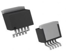
BT152-800R,127 Package

BT152-800R,127 Package
BT152-800R,127 Manufacturer
WeEn Semiconductors Co., Ltd, is the global joint venture between NXP Semiconductors N.V. and Beijing JianGuang Asset Management Co. Ltd (JAC Capital). WeEn Semiconductors was officially opened on 19th January 2016 with the business and operations centre located in Shanghai, China. The NXP Bi-Polar Division product portfolio (Diodes, Thyristors & Transistors) has been transferred to WeEn Semiconductors (Jan 19, 2017).
Specifications
- TypeParameter
- Mounting Type
The "Mounting Type" in electronic components refers to the method used to attach or connect a component to a circuit board or other substrate, such as through-hole, surface-mount, or panel mount.
Through Hole - Package / Case
refers to the protective housing that encases an electronic component, providing mechanical support, electrical connections, and thermal management.
TO-220-3 - Surface Mount
having leads that are designed to be soldered on the side of a circuit board that the body of the component is mounted on.
NO - Number of Elements1
- Voltage-Off State800V
- Operating Temperature
The operating temperature is the range of ambient temperature within which a power supply, or any other electrical equipment, operate in. This ranges from a minimum operating temperature, to a peak or maximum operating temperature, outside which, the power supply may fail.
-40°C~125°C - Packaging
Semiconductor package is a carrier / shell used to contain and cover one or more semiconductor components or integrated circuits. The material of the shell can be metal, plastic, glass or ceramic.
Tube - JESD-609 Code
The "JESD-609 Code" in electronic components refers to a standardized marking code that indicates the lead-free solder composition and finish of electronic components for compliance with environmental regulations.
e3 - Part Status
Parts can have many statuses as they progress through the configuration, analysis, review, and approval stages.
Active - Moisture Sensitivity Level (MSL)
Moisture Sensitivity Level (MSL) is a standardized rating that indicates the susceptibility of electronic components, particularly semiconductors, to moisture-induced damage during storage and the soldering process, defining the allowable exposure time to ambient conditions before they require special handling or baking to prevent failures
1 (Unlimited) - Number of Terminations3
- Terminal Finish
Terminal Finish refers to the surface treatment applied to the terminals or leads of electronic components to enhance their performance and longevity. It can improve solderability, corrosion resistance, and overall reliability of the connection in electronic assemblies. Common finishes include nickel, gold, and tin, each possessing distinct properties suitable for various applications. The choice of terminal finish can significantly impact the durability and effectiveness of electronic devices.
TIN - HTS Code
HTS (Harmonized Tariff Schedule) codes are product classification codes between 8-1 digits. The first six digits are an HS code, and the countries of import assign the subsequent digits to provide additional classification. U.S. HTS codes are 1 digits and are administered by the U.S. International Trade Commission.
8541.30.00.80 - Terminal Position
In electronic components, the term "Terminal Position" refers to the physical location of the connection points on the component where external electrical connections can be made. These connection points, known as terminals, are typically used to attach wires, leads, or other components to the main body of the electronic component. The terminal position is important for ensuring proper connectivity and functionality of the component within a circuit. It is often specified in technical datasheets or component specifications to help designers and engineers understand how to properly integrate the component into their circuit designs.
SINGLE - Peak Reflow Temperature (Cel)
Peak Reflow Temperature (Cel) is a parameter that specifies the maximum temperature at which an electronic component can be exposed during the reflow soldering process. Reflow soldering is a common method used to attach electronic components to a circuit board. The Peak Reflow Temperature is crucial because it ensures that the component is not damaged or degraded during the soldering process. Exceeding the specified Peak Reflow Temperature can lead to issues such as component failure, reduced performance, or even permanent damage to the component. It is important for manufacturers and assemblers to adhere to the recommended Peak Reflow Temperature to ensure the reliability and functionality of the electronic components.
NOT SPECIFIED - Time@Peak Reflow Temperature-Max (s)
Time@Peak Reflow Temperature-Max (s) refers to the maximum duration that an electronic component can be exposed to the peak reflow temperature during the soldering process, which is crucial for ensuring reliable solder joint formation without damaging the component.
NOT SPECIFIED - Base Part Number
The "Base Part Number" (BPN) in electronic components serves a similar purpose to the "Base Product Number." It refers to the primary identifier for a component that captures the essential characteristics shared by a group of similar components. The BPN provides a fundamental way to reference a family or series of components without specifying all the variations and specific details.
BT152 - Reference Standard
In the context of electronic components, the term "Reference Standard" typically refers to a specific set of guidelines, specifications, or requirements that serve as a benchmark for evaluating the quality, performance, and characteristics of the component. These standards are established by organizations such as the International Electrotechnical Commission (IEC), the Institute of Electrical and Electronics Engineers (IEEE), or specific industry bodies.Reference standards help ensure consistency and interoperability among different components, as they provide a common framework for manufacturers, designers, and users to adhere to. They outline parameters such as electrical properties, mechanical dimensions, environmental conditions, and safety considerations that the component must meet to be considered compliant.By referencing these standards, manufacturers can design and produce components that meet industry-recognized criteria, which in turn helps users select the right components for their applications with confidence. Adhering to reference standards also facilitates regulatory compliance and promotes overall quality and reliability in electronic systems.
IEC-60134 - JESD-30 Code
JESD-30 Code refers to a standardized descriptive designation system established by JEDEC for semiconductor-device packages. This system provides a systematic method for generating designators that convey essential information about the package's physical characteristics, such as size and shape, which aids in component identification and selection. By using JESD-30 codes, manufacturers and engineers can ensure consistency and clarity in the specification of semiconductor packages across various applications and industries.
R-PSFM-T3 - Configuration
The parameter "Configuration" in electronic components refers to the specific arrangement or setup of the components within a circuit or system. It encompasses how individual elements are interconnected and their physical layout. Configuration can affect the functionality, performance, and efficiency of the electronic system, and may influence factors such as signal flow, impedance, and power distribution. Understanding the configuration is essential for design, troubleshooting, and optimizing electronic devices.
SINGLE - Case Connection
Case Connection refers to the method by which an electronic component's case or housing is connected to the electrical circuit. This connection is important for grounding purposes, mechanical stability, and heat dissipation. The case connection can vary depending on the type of component and its intended application. It is crucial to ensure a secure and reliable case connection to maintain the overall performance and safety of the electronic device.
ANODE - Trigger Device Type
Trigger Device Type is a parameter in electronic components that refers to the type of device or mechanism used to initiate a specific action or function within the component. This parameter specifies the specific trigger device, such as a sensor, switch, or signal input, that is required to activate or control the operation of the component. Understanding the trigger device type is crucial for proper integration and operation of the electronic component within a larger system or circuit. By specifying the appropriate trigger device type, engineers and designers can ensure that the component functions correctly and responds to the intended input signals or conditions.
SCR - Voltage - Gate Trigger (Vgt) (Max)
Voltage - Gate Trigger (Vgt) (Max) refers to the maximum voltage level required to trigger the gate of a semiconductor device, such as a thyristor or triac, into the conductive state. When the gate receives this voltage, it initiates the device's conduction, allowing current to flow between its anode and cathode. Exceeding this voltage can lead to unwanted behavior or damage to the component, making it a critical parameter in designing circuits that utilize these devices. Understanding Vgt is essential for ensuring proper operation and reliability in electronic applications.
1.5V - Current - Non Rep. Surge 50, 60Hz (Itsm)
The parameter "Current - Non Rep. Surge 50, 60Hz (Itsm)" in electronic components refers to the maximum non-repetitive surge current that a component can withstand without damage during a single surge event at frequencies of 50Hz or 60Hz. This parameter is important for assessing the robustness and reliability of the component in handling sudden spikes or surges in current that may occur in the electrical system. It helps in determining the level of protection needed for the component to ensure its longevity and proper functioning in various operating conditions. Manufacturers provide this specification to guide engineers and designers in selecting the appropriate components for their applications based on the expected surge current levels.
200A 220A - Current - Gate Trigger (Igt) (Max)
Current - Gate Trigger (Igt) (Max) refers to the maximum gate trigger current required to activate a semiconductor device, such as a thyristor or triac. It is the minimum current that must flow into the gate terminal to ensure that the device turns on and conducts current between its anode and cathode. Exceeding this value can lead to unnecessary power consumption, while insufficient current may prevent the device from turning on effectively. This parameter is crucial for circuit design, as it influences the selection of gate driving circuits.
32mA - Current - Hold (Ih) (Max)
The parameter "Current - Hold (Ih) (Max)" in electronic components refers to the maximum current required to maintain the component in a latched or on-state after it has been triggered. This parameter is commonly associated with relays, switches, and other devices that have a latching function. It is important because it determines the minimum current that must be supplied to keep the component in its activated state, ensuring reliable operation. Exceeding the maximum Ih value can lead to the component failing to hold its state, potentially causing malfunctions or disruptions in the circuit.
60mA - Current - On State (It (RMS)) (Max)
The parameter "Current - On State (It (RMS)) (Max)" refers to the maximum root mean square (RMS) current that an electronic component, typically a semiconductor device like a thyristor or a transistor, can handle while in the on state without sustaining damage. This value is crucial for ensuring that the component operates safely under load conditions. Exceeding this maximum rating can result in overheating, degradation, or failure of the component over time. It is an important specification for designers to consider when selecting components for a circuit to ensure reliable performance.
20A - Repetitive Peak Off-state Voltage
The Repetitive Peak Off-state Voltage (Vdrm) is a key parameter in electronic components, particularly in devices like thyristors and triacs. It refers to the maximum voltage that can be applied across the component when it is in the off-state without triggering it to turn on. This parameter is crucial for ensuring the proper functioning and reliability of the component in various circuit applications. It helps determine the voltage level at which the component can safely operate without experiencing unintended conduction. Designers need to consider the Vdrm rating to prevent damage to the component and maintain the overall performance of the circuit.
800V - Current - On State (It (AV)) (Max)
The parameter "Current - On State (It (AV)) (Max)" in electronic components refers to the maximum average current that a component, typically a switch or semiconductor device, can handle while in the 'on' state without overheating or failing. This rating is crucial for ensuring reliable operation in circuits where the component is subjected to continuous current flow. Exceeding this maximum value can lead to damage or malfunction, so it is important for designers to consider it when selecting components for their applications.
13A - SCR Type
SCR Type refers to a category of semiconductor devices specifically designed to control and manage electrical energy in electronic circuits. It stands for Silicon Controlled Rectifier, which is a type of thyristor that can switch and control voltage and current flow. SCRs are commonly used in applications such as motor control, power regulation, and lighting control due to their ability to handle high power loads. The SCR Type includes variations like standard SCRs, gate turn-off thyristors, and triacs, each serving specific purposes in power electronics.
Standard Recovery - Voltage - On State (Vtm) (Max)
The parameter "Voltage - On State (Vtm) (Max)" refers to the maximum voltage drop across a semiconductor device when it is in the on state and conducting current. It is a critical specification for devices such as transistors, diodes, and thyristors, as it affects the overall power loss and efficiency of the component during operation. A lower Vtm value indicates better efficiency, as it leads to reduced power dissipation in the form of heat. This parameter is essential for engineers to consider when designing circuits that require low voltage drops for optimal performance.
1.75V - Current - Off State (Max)
The parameter "Current - Off State (Max)" refers to the maximum current that can flow through an electronic component when it is in the off state, typically when the component is not conducting electricity. This specification is important for components such as transistors, diodes, and switches, as it indicates the maximum leakage current that can occur when the component is supposed to be non-conductive. Exceeding this maximum off-state current can lead to unintended power consumption, overheating, or malfunction of the component. Designers need to consider this parameter to ensure proper functioning and reliability of the electronic circuit.
1mA - Repetitive Peak Reverse Voltage
The Repetitive Peak Reverse Voltage (VRRM) is a key parameter in electronic components, particularly in diodes and rectifiers. It refers to the maximum reverse voltage that a component can withstand in repetitive peak reverse polarity conditions without breaking down. This parameter is crucial for ensuring the reliable operation and longevity of the component in circuits where reverse voltage may be present intermittently or periodically. It is important to select a component with a VRRM rating higher than the maximum reverse voltage expected in the circuit to prevent damage or failure.
800V - RoHS Status
RoHS means “Restriction of Certain Hazardous Substances” in the “Hazardous Substances Directive” in electrical and electronic equipment.
RoHS Compliant
Datasheet PDF
- PCN Part Status Change :
- PCN Assembly/Origin :
- PCN Other :
- PCN Packaging :
- Datasheets :
What is BT152-800R,127?
BT152-800R,127 Thyristor is a planar passivated Silicon Controlled Rectifier in a SOT78 (TO-220AB) plastic package intended for use in applications requiring very high inrush current capability and high thermal cycling performance.
What is the operating temperature of BT152-800R,127?
-40°C~125°C.
What is the reference standard of BT152-800R,127?
IEC-60134.
 ESP8266EX SMD IC QFN32-pin: Features, Datasheet,Pinout, and Application
08 January 20222051
 Exploring the PIC16F72X Series: In-depth Analysis and Applications
29 February 2024116
 An Introduction to the AD7545 Digital to Analog Converter (DAC)
06 March 2024234
 Texas Instruments TMUX1574RSVR: Steps to Solve Common Issues
16 August 2025246
 LME49600 Audio Buffer: Datasheet, Pinout and Schematic
31 August 20212455
 M95512-R 512-Kbit serial SPI bus EEPROM: Pinout, Equivalent and Datasheet
07 April 20224691
 TL431A Integrated Circuit: Pinout, Equivalent and Datasheet
12 November 20217277
 TPS63070RNMR Buck-Boost Converter, 2V-16V Wide input voltage
18 March 20221863
 Working Principle and Application of Infrared Sensors
27 October 202515962
 Introduction to Wireless Charger
27 July 20215874
 What Is An Intrinsic Semiconductor?
03 November 202010458
 Working and Types of Touch Screen
20 March 20215836
 Comparing Popular Jumper Wires for Electronics Projects
10 July 20251421
 How does a Resettable Fuse Work?
26 August 202036308
 Introduction to PCB Layout Principles
13 November 20206408
 UTMEL- Sale Promotion
20 June 20234125
WeEn Semiconductors
In Stock: 10
Minimum: 1 Multiples: 1
Qty
Unit Price
Ext Price
1
$0.630181
$0.63
10
$0.594510
$5.95
100
$0.560859
$56.09
500
$0.529112
$264.56
1000
$0.499162
$499.16
Not the price you want? Send RFQ Now and we'll contact you ASAP.
Inquire for More Quantity
![BT152-600R,127]() BT152-600R,127
BT152-600R,127WeEn Semiconductors
![BT258-800R,127]() BT258-800R,127
BT258-800R,127WeEn Semiconductors
![BT145-800R,127]() BT145-800R,127
BT145-800R,127WeEn Semiconductors
![BT151S-650R,118]() BT151S-650R,118
BT151S-650R,118WeEn Semiconductors
![BT258X-800R,127]() BT258X-800R,127
BT258X-800R,127WeEn Semiconductors
![BT145-800RTQ]() BT145-800RTQ
BT145-800RTQWeEn Semiconductors
![BT151X-800C,127]() BT151X-800C,127
BT151X-800C,127WeEn Semiconductors
![TYN20X-800T,127]() TYN20X-800T,127
TYN20X-800T,127WeEn Semiconductors
![TYN16X-600RT,127]() TYN16X-600RT,127
TYN16X-600RT,127WeEn Semiconductors


