
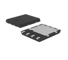
Texas Instruments TMUX1574RSVR: Steps to Solve Common Issues

35μs, 95ns SPDT 4.5Ohm QUAD Analog Switches TMUX1574 100nA 16-UFQFN
Unit Price: $0.450183
Ext Price: $0.45


35μs, 95ns SPDT 4.5Ohm QUAD Analog Switches TMUX1574 100nA 16-UFQFN
Troubleshoot Texas Instruments TMUX1574RSVR issues with step-by-step checks for power, signals, and control pins to resolve channel switching and signal faults.
Product Introduction
You want your texas instruments tmux1574rsvr to work without trouble. Start by checking each part of your setup. Look at the power, the signals, and the control pins. Use simple tools like a multimeter or oscilloscope for fast checks. If you test step by step, you can find problems early. The texas instruments tmux1574rsvr will show clear results if you follow a careful process. Make sure you check the environment as well.
Power & Startup
Check Voltage
You need to check the supply voltage first. The TMUX1574RSVR works best when you use the correct voltage. If you use the wrong voltage, the device may not start or could get damaged.
The TMUX1574RSVR supports a wide operating supply voltage range from 1.5 V to 5.5 V.
This range lets you use the device in many places, such as servers, communication equipment, and industrial machines.
The device can handle signals up to 5.5 V for both input and output.
The maximum supply voltage is 5.5 V, which matches the highest signal voltage.
Use a multimeter to measure the voltage at the VDD pin. Make sure the reading stays inside the 1.5 V to 5.5 V range. If the voltage is too low or too high, the TMUX1574RSVR will not work as expected. Many embedded systems use this voltage range, so you can use the TMUX1574RSVR in different embedded projects.
Tip: Always check the voltage before you power up your board. This step can save your device from damage.
Inspect Power Connections
After you check the voltage, look at the power connections. Loose or broken wires can stop the TMUX1574RSVR from working. You should:
Inspect the VDD and GND pins for solid connections.
Make sure there are no cold solder joints or broken traces on the PCB.
Check for short circuits between power and ground.
If you use the TMUX1574RSVR in embedded designs, you must keep the power lines clean and stable. Noise or drops in power can cause problems in embedded systems. You can use a continuity tester to check for good connections. If you find a problem, fix it before you move to the next step.
Device Initialization
Once you confirm the power is good, you need to make sure the device starts up the right way. The TMUX1574RSVR needs a proper startup sequence to work in embedded circuits.
Wait for the supply voltage to reach a stable value before you send any control signals.
Make sure the logic levels on the control pins match the voltage you use for VDD.
Some embedded systems use power-on reset circuits to help with startup. If your design has one, check that it works.
If the device does not start, check the timing of your power and control signals. You can use an oscilloscope to watch the signals during startup. This step helps you see if the TMUX1574RSVR gets the right signals at the right time. Good device initialization is important for all embedded projects, especially when you use multiplexers like the TMUX1574RSVR.
Signal & Channels
Oscilloscope Check
You can use an oscilloscope to see what happens on the signal lines. This tool helps you watch the signals as they move through the TMUX1574RSVR. Place the oscilloscope probe on the input and output pins. Look for clean, sharp waveforms. If you see noise, missing parts, or strange shapes, you may have a problem with your circuit or the multiplexer.
Tip: A stable and clear signal means your multiplexer works well. If you see a flat line or a lot of noise, check your connections and power supply first.
In embedded systems, an oscilloscope helps you find problems fast. You can compare the input and output signals to see if the TMUX1574RSVR passes the signal correctly. This step is important for both simple and complex embedded projects.
Test All I/O Pins
You should test every I/O pin on the TMUX1574RSVR. This process helps you find faults in the multiplexer channels. The device acts like a resistor when it switches signals. It does not set digital voltage levels on its I/O pins. The logic control pins have set thresholds, but the source and drain pins only pass signals.
Systematic I/O pin testing checks if each channel works as it should.
You can find out if a channel is stuck open, shorted, or has the wrong resistance.
The TMUX1574RSVR only passes signals. It does not drive them.
Testing the I/O pins helps you see if the problem is inside the multiplexer or somewhere else in your system.
Voltage on the source and drain pins depends on what you connect to them. Testing helps you know if the multiplexer causes the issue or if it comes from another part.
You can use a multimeter to check continuity and resistance. This method works well in embedded designs, where you need to know if the multiplexer or another part causes the problem.
Channel Switching
Check if the TMUX1574RSVR switches channels as you expect. Use the control pins to select different channels. Watch the output with your oscilloscope or logic analyzer. The output should follow the input signal when you switch channels.
If the output does not change, you may have a problem with the control logic or the multiplexer itself. Make sure the control signals match the voltage levels for your system. In embedded systems, timing and logic levels matter a lot. A small mistake in the control signal can stop the multiplexer from working.
Note: Always double-check your control signals. Wrong logic levels or timing can cause the TMUX1574RSVR to stay on the wrong channel.
Signal Loss or Distortion
Signal loss or distortion can happen for many reasons. The TMUX1574RSVR has some key parameters that affect signal quality. You should know these when you design or troubleshoot your circuit.
| Parameter | Description | Impact on Signal Loss or Distortion |
|---|---|---|
| On-State Resistance (Ron) | Resistance when the switch is on, max 4.5 Ohm | Causes voltage drop and power dissipation, leading to signal attenuation |
| Charge Injection | Level changes caused by stray capacitance in MOSFET switches, approx. 3.5 pC | Introduces signal level distortion due to charge transfer during switching |
| Channel-to-Channel Matching (ΔRon) | Variation in on-resistance between channels, approx. 70 mΩ | Causes non-uniform signal integrity across channels, affecting consistency |
| Channel Capacitances (CS(off), CD(off)) | Capacitances when the switch is off, approx. 3.5 pF each | Affects high-frequency performance, causing signal distortion at higher frequencies |
| Switch Time (Ton, Toff) | Time to switch on/off, max 35 μs (Ton), 95 ns (Toff) | Timing delays can introduce distortion in signal timing and waveform integrity |
| Leakage Current (IS(off)) | Current leakage when switch is off, max 100 nA | Can cause minor signal degradation and power inefficiency |
These parameters can cause voltage drops, timing delays, or changes in your signal. If you see signal loss or distortion, check these values in your design. High on-state resistance can lower your signal strength. Charge injection and channel capacitance can change the shape of fast signals. In embedded projects, these effects can make a big difference, especially at high speeds.
Alert: If you notice signal problems, review your layout and check the datasheet for these parameters. Small changes in your design can fix many signal issues.
Logic & Control
Test Logic Levels
You need to check the logic levels on the control pins of the TMUX1574RSVR. The device works with logic thresholds that match 1.8 V logic. This means you can use both TTL and CMOS logic signals. The datasheet confirms that all control inputs support 1.8 V logic compatibility. You can connect the multiplexer to many types of microcontrollers in embedded systems. The TMUX1574RSVR also has fail-safe logic and built-in pull-down resistors on the control pins. These features help protect your circuit from floating signals or unexpected voltage spikes.
Tip: Use a logic analyzer or a simple voltmeter to check the voltage on each control pin. Make sure the voltage matches the logic levels your system uses.
SPI Switching
Many embedded projects use SPI to control multiplexers. You can use SPI signals to switch channels on the TMUX1574RSVR. First, connect the SPI lines to the control pins. Then, send the right data pattern from your microcontroller. The multiplexer will change channels based on the logic state of the control pins. If you see problems, check the SPI clock and data lines for noise or timing errors.
Make sure the SPI voltage matches the logic level requirements.
Watch for glitches or missed signals on the oscilloscope.
Test each channel by sending different SPI commands.
You can use this method to automate channel switching in embedded systems.
Timing & Protocol
Timing matters when you use multiplexers in embedded designs. The TMUX1574RSVR responds quickly to changes on the control pins, but you must give it enough time to switch. If you change channels too fast, you might see glitches or missed signals. Always check the timing diagrams in the datasheet. Wait for the switch time before you read or write data through the multiplexer.
| Parameter | Typical Value | What It Means |
|---|---|---|
| Switch On Time | 35 μs | Time to turn on a channel |
| Switch Off Time | 95 ns | Time to turn off a channel |
Note: Good timing helps you avoid errors in your embedded circuits. Always test your protocol with real signals.
PCB & Environment
PCB Layout
You need to pay close attention to your PCB layout when you use the TMUX1574RSVR. Good layout helps your circuit work better and makes troubleshooting easier. Place the multiplexer close to the devices it connects. Short traces reduce signal loss and lower the chance of interference. Keep the signal paths straight and avoid sharp corners. You should also separate analog and digital signals if your design uses both. This step helps prevent unwanted noise from reaching sensitive parts.
Tip: Use a ground plane under your signal traces. This design choice can help control noise and improve signal quality.
Grounding & Noise
Proper grounding is important for any circuit. You want to connect all ground points to a single ground plane. This method stops ground loops and reduces noise. If you see strange signals or glitches, check your ground connections first. Noise can enter your system from many sources, such as power supplies or nearby circuits. Shield your signal lines if you work in a noisy environment. You can also add small capacitors between power and ground pins to filter out high-frequency noise.
| Problem | Solution |
|---|---|
| Ground loops | Use a single ground plane |
| High-frequency noise | Add bypass capacitors |
| Signal crosstalk | Separate signal traces |
Environmental Factors
You should always consider the environment where your circuit will run. High temperatures, humidity, or dust can affect the TMUX1574RSVR. If you use the device in an embedded system, make sure you keep it within the recommended temperature range. Protect your board from moisture and static electricity. Use enclosures or conformal coatings for harsh environments. Regular checks help you spot problems early and keep your embedded projects running smoothly.
Alert: Never ignore the effects of temperature and humidity. These factors can cause hidden problems that are hard to find later.
Device Faults & Replacement
Overvoltage/Overcurrent
You must protect your ic from overvoltage and overcurrent. These problems can damage the TMUX1574RSVR quickly. If you apply a voltage higher than 5.5 V to the VDD pin, the ic may fail. Overcurrent can also cause the ic to heat up or stop working. You should always use a fuse or a current-limiting resistor in your circuit. These parts help keep your ic safe. If you see signs of overheating, turn off the power right away.
Tip: Use a multimeter to check for high voltage or current before you connect the ic to your system.
Fault Indicators
You can spot a faulty ic by looking for certain signs. If the TMUX1574RSVR gets hot, you may have a short circuit or too much current. Sometimes, the ic will not switch channels or pass signals. You might see no output or a weak signal. In some cases, the ic may show visible damage, like burn marks or a cracked package.
Here is a quick checklist:
No signal at output pins
Device feels hot to the touch
Burn marks on the ic
Channels do not switch
A working integrated circuit should not show any of these problems.
Replace TMUX1574RSVR
If you find a faulty ic, you need to replace it. First, turn off all power to your board. Use a soldering iron to remove the damaged ic. Clean the pads on the PCB before you place a new ic. Make sure you align the new ic with the correct orientation. Solder each pin carefully. After you finish, check your work for solder bridges or loose pins.
Note: Always test your circuit after you replace the ic. This step helps you make sure the new ic works as expected.
texas instruments tmux1574rsvr Resources
Documentation & Tools
When you troubleshoot the texas instruments tmux1574rsvr, you should always start with the official datasheet. This document gives you the most reliable and up-to-date information. The datasheet explains the device’s features, pin layout, electrical limits, and timing diagrams. You can find details about voltage ranges, logic levels, and switching times. If you want to check signal paths or power requirements, the datasheet will guide you step by step.
Tip: Keep the datasheet open while you work. You can quickly look up pin functions or recommended operating conditions.
You may also use online tools from Texas Instruments. These tools help you simulate circuits or check compatibility with other devices. Some tools let you enter your circuit values and see how the multiplexer will behave. This saves you time and helps you avoid mistakes.
Here is a quick list of helpful resources:
TMUX1574RSVR official datasheet (primary source)
Texas Instruments simulation tools
Application notes for multiplexers
Community Support
You do not have to solve every problem alone. Many engineers and hobbyists use the texas instruments tmux1574rsvr in their projects. You can join online forums or support communities to ask questions and share your experience. The Texas Instruments E2E Community is a good place to start. You can post your issue and get answers from experts or other users.
If you search for your problem, you might find that someone else has already solved it. You can also read troubleshooting tips or see example circuits. Community support helps you learn faster and avoid common mistakes.
Note: Always describe your problem clearly when you ask for help. Include details like your circuit diagram, voltage levels, and what you have tested so far.
You can solve most issues with the texas instruments tmux1574rsvr by following a clear troubleshooting process. Start with power checks, then test signals and logic. Always look at your environment. Use the datasheet and online forums if you need more help. If problems continue, try replacing the device or ask for expert support. Careful steps lead to better results.
FAQ
What should you do if the TMUX1574RSVR does not switch channels?
Check the control pins first. Make sure you send the correct logic levels. Use a multimeter or logic analyzer to confirm the signals. If the device still does not switch, inspect the power supply and replace the IC if needed.
Can you use the TMUX1574RSVR with 3.3V logic systems?
Yes, you can use the TMUX1574RSVR with 3.3V logic. The device supports a wide voltage range from 1.5V to 5.5V. Always match your control signals to the supply voltage for best results.
How do you prevent signal distortion with this multiplexer?
Keep your PCB traces short and use a solid ground plane. Add bypass capacitors near the power pins. Avoid running high-speed signals next to noisy lines. These steps help you reduce signal loss and distortion.
What tools help you troubleshoot the TMUX1574RSVR?
You can use a multimeter to check voltages and continuity. An oscilloscope lets you see signal waveforms. A logic analyzer helps you monitor control signals. These tools make troubleshooting faster and more accurate.
Where can you find more support for TMUX1574RSVR issues?
Visit the Texas Instruments E2E Community for expert advice.
Download the official datasheet for detailed information.
Search online forums for similar problems and solutions.
These resources help you solve most issues quickly.
Specifications
- TypeParameter
- Factory Lead Time6 Weeks
- Mounting Type
The "Mounting Type" in electronic components refers to the method used to attach or connect a component to a circuit board or other substrate, such as through-hole, surface-mount, or panel mount.
Surface Mount - Package / Case
refers to the protective housing that encases an electronic component, providing mechanical support, electrical connections, and thermal management.
16-UFQFN - Surface Mount
having leads that are designed to be soldered on the side of a circuit board that the body of the component is mounted on.
YES - Operating Temperature
The operating temperature is the range of ambient temperature within which a power supply, or any other electrical equipment, operate in. This ranges from a minimum operating temperature, to a peak or maximum operating temperature, outside which, the power supply may fail.
-40°C~125°C TA - Packaging
Semiconductor package is a carrier / shell used to contain and cover one or more semiconductor components or integrated circuits. The material of the shell can be metal, plastic, glass or ceramic.
Cut Tape (CT) - Pbfree Code
The "Pbfree Code" parameter in electronic components refers to the code or marking used to indicate that the component is lead-free. Lead (Pb) is a toxic substance that has been widely used in electronic components for many years, but due to environmental concerns, there has been a shift towards lead-free alternatives. The Pbfree Code helps manufacturers and users easily identify components that do not contain lead, ensuring compliance with regulations and promoting environmentally friendly practices. It is important to pay attention to the Pbfree Code when selecting electronic components to ensure they meet the necessary requirements for lead-free applications.
yes - Part Status
Parts can have many statuses as they progress through the configuration, analysis, review, and approval stages.
Active - Moisture Sensitivity Level (MSL)
Moisture Sensitivity Level (MSL) is a standardized rating that indicates the susceptibility of electronic components, particularly semiconductors, to moisture-induced damage during storage and the soldering process, defining the allowable exposure time to ambient conditions before they require special handling or baking to prevent failures
1 (Unlimited) - Number of Terminations16
- Terminal Position
In electronic components, the term "Terminal Position" refers to the physical location of the connection points on the component where external electrical connections can be made. These connection points, known as terminals, are typically used to attach wires, leads, or other components to the main body of the electronic component. The terminal position is important for ensuring proper connectivity and functionality of the component within a circuit. It is often specified in technical datasheets or component specifications to help designers and engineers understand how to properly integrate the component into their circuit designs.
QUAD - Terminal Form
Occurring at or forming the end of a series, succession, or the like; closing; concluding.
NO LEAD - Number of Functions1
- Base Part Number
The "Base Part Number" (BPN) in electronic components serves a similar purpose to the "Base Product Number." It refers to the primary identifier for a component that captures the essential characteristics shared by a group of similar components. The BPN provides a fundamental way to reference a family or series of components without specifying all the variations and specific details.
TMUX1574 - JESD-30 Code
JESD-30 Code refers to a standardized descriptive designation system established by JEDEC for semiconductor-device packages. This system provides a systematic method for generating designators that convey essential information about the package's physical characteristics, such as size and shape, which aids in component identification and selection. By using JESD-30 codes, manufacturers and engineers can ensure consistency and clarity in the specification of semiconductor packages across various applications and industries.
R-PQCC-N16 - Number of Channels1
- Number of Circuits4
- Bandwidth
In electronic components, "Bandwidth" refers to the range of frequencies over which the component can effectively operate or pass signals without significant loss or distortion. It is a crucial parameter for devices like amplifiers, filters, and communication systems. The bandwidth is typically defined as the difference between the upper and lower frequencies at which the component's performance meets specified criteria, such as a certain level of signal attenuation or distortion. A wider bandwidth indicates that the component can handle a broader range of frequencies, making it more versatile for various applications. Understanding the bandwidth of electronic components is essential for designing and optimizing circuits to ensure proper signal transmission and reception within the desired frequency range.
2000MHz - -3db Bandwidth
The "-3dB bandwidth" of an electronic component refers to the frequency range over which the component's output signal power is reduced by 3 decibels (dB) compared to its maximum output power. This parameter is commonly used to describe the frequency response of components such as amplifiers, filters, and other signal processing devices. The -3dB point is significant because it represents the half-power point, where the output signal power is reduced to half of its maximum value. Understanding the -3dB bandwidth is important for designing and analyzing electronic circuits to ensure that signals are accurately processed within the desired frequency range.
2GHz - On-State Resistance (Max)
The "On-State Resistance (Max)" parameter in electronic components refers to the maximum resistance exhibited by the component when it is in the fully conducting state. This resistance is typically measured when the component is carrying the maximum specified current. A lower on-state resistance indicates better conductivity and efficiency of the component when it is in the on-state. It is an important parameter to consider when selecting components for applications where low power dissipation and high efficiency are critical factors.
4.5Ohm - Multiplexer/Demultiplexer Circuit
A Multiplexer/Demultiplexer Circuit is an electronic component used in digital circuits to select one of several input signals and route it to a single output. A multiplexer, also known as a "mux," is used to combine multiple input signals into a single output, while a demultiplexer, also known as a "demux," is used to take a single input and route it to one of several possible outputs. These circuits are commonly used in data transmission, communication systems, and digital signal processing applications to efficiently manage and control the flow of data. Multiplexers and demultiplexers play a crucial role in optimizing the use of resources and improving the overall performance of electronic systems.
2:1 - Current - Leakage (IS(off)) (Max)
Current - Leakage (IS(off)) (Max) refers to the maximum amount of current that flows through a device when it is in its off state, meaning it is not conducting or not intended to be active. This parameter is crucial in determining the efficiency of electronic components, especially in battery-operated devices, as higher leakage currents can lead to increased power consumption and reduced battery life. It is typically measured in microamperes (µA) or milliamperes (mA) and helps engineers assess the suitability of a component for low-power applications.
100nA - Channel Capacitance (CS(off), CD(off))
Channel capacitance (CS(off), CD(off)) in electronic components refers to the capacitance associated with the channel of a field-effect transistor (FET) when it is turned off. CS(off) represents the capacitance between the source and the gate of the FET, while CD(off) represents the capacitance between the drain and the gate. These capacitances play a crucial role in determining the high-frequency performance and switching characteristics of the FET. Understanding and controlling these capacitances is essential for optimizing the performance of electronic circuits, especially in high-speed applications where minimizing parasitic capacitances is critical for achieving desired signal integrity and efficiency.
3.5pF 3.5pF - Switch Circuit
establishes connections between links, on demand and as available, in order to establish an end-to-end circuit between devices.
SPDT - Switch Time (Ton, Toff) (Max)
The parameter "Switch Time (Ton, Toff) (Max)" in electronic components refers to the maximum time it takes for a device to transition between its on and off states. Ton represents the turn-on time, which is the time taken for the device to switch from the off state to the on state, while Toff represents the turn-off time, which is the time taken for the device to switch from the on state to the off state. This parameter is crucial in determining the speed and efficiency of the device's switching operation. A shorter switch time generally indicates faster switching speeds and better performance of the electronic component.
35μs, 95ns - Charge Injection
A Charge injection in analog switches and multiplexers is a level change caused by stray capacitance associated with the NMOS and PMOS transistors that make up the analog switch.
3.5pC - Channel-to-Channel Matching (ΔRon)
Channel-to-Channel Matching (ΔRon) refers to the variation in the on-resistance of multiple channels within a multi-channel electronic component, such as a multiplexer or a switch. It is a measure of how closely the on-resistance values of different channels match each other. The lower the ΔRon value, the better the matching between channels, which is important for ensuring consistent performance across all channels in a system. Channel-to-Channel Matching is critical in applications where precise and uniform signal processing is required, such as in instrumentation, audio equipment, and communication systems. Manufacturers provide specifications for ΔRon to help designers select components that meet their performance requirements.
70m Ω - Length2.6mm
- Height Seated (Max)
Height Seated (Max) is a parameter in electronic components that refers to the maximum allowable height of the component when it is properly seated or installed on a circuit board or within an enclosure. This specification is crucial for ensuring proper fit and alignment within the overall system design. Exceeding the maximum seated height can lead to mechanical interference, electrical shorts, or other issues that may impact the performance and reliability of the electronic device. Manufacturers provide this information to help designers and engineers select components that will fit within the designated space and function correctly in the intended application.
0.55mm - RoHS Status
RoHS means “Restriction of Certain Hazardous Substances” in the “Hazardous Substances Directive” in electrical and electronic equipment.
ROHS3 Compliant
 STL100N8F7 N-channel Power MOSFET: Datasheet, Pinout, Test Circuit
24 August 2021612
 BC327 PNP Transistor: Equivalents, Uses, and Pinout
12 August 202112250
 CR2032 VS DL2032 VS CR2025: Are they interchangeable?
24 February 202221373
 STMicroelectronics STM32F302CBT6: Integration Guide for Embedded Systems
11 June 2025120
![NRF9160 RF Evaluation and Development Kits[Video]: Datasheet, Features,and Applications](https://res.utmel.com/Images/Article/7513b588-4ca0-4fca-a83b-1b427fb11de6.png) NRF9160 RF Evaluation and Development Kits[Video]: Datasheet, Features,and Applications
NRF9160 RF Evaluation and Development Kits[Video]: Datasheet, Features,and Applications13 April 20222962
 TDA2040 Hi-Fi Audio Power Amplifier: Replacement, Circuit and Datasheet
28 October 20216011
 ADC0804 ADC: Datasheet, Schematic, Pinout
09 October 202110623
![BT136 Triac: Datasheet, Pinout, Equivalent [FAQ+Video]](https://res.utmel.com/Images/Article/0be48a6e-a6da-45ab-8fe4-5479340e5205.jpg) BT136 Triac: Datasheet, Pinout, Equivalent [FAQ+Video]
BT136 Triac: Datasheet, Pinout, Equivalent [FAQ+Video]02 April 20227577
 DDR5: The New Generation of Memory Standard
28 September 20216903
 What is a Lithium-ion Battery?
03 March 20214629
 What is SPI (Serial Perripheral Interface)?
25 November 20213888
 Introduction to Acceleration Sensors
07 November 20257392
 Building a Smart Home System: Exploring Arduino Applications
13 March 20242349
 Applications of FPGAs in Artificial Intelligence: A Comprehensive Guide
29 August 20251461
 Top Batteries That Can Replace LR44
09 June 20251208
 The Historical Milestones of Coaxial Cable Development
19 July 20251113
Texas Instruments
In Stock: 6745
Minimum: 1 Multiples: 1
Qty
Unit Price
Ext Price
1
$0.450183
$0.45
10
$0.424701
$4.25
100
$0.400661
$40.07
500
$0.377982
$188.99
1000
$0.356587
$356.59
Not the price you want? Send RFQ Now and we'll contact you ASAP.
Inquire for More Quantity
![CD74HC4053PWR]() CD74HC4053PWR
CD74HC4053PWRTexas Instruments
![CD4052BPWR]() CD4052BPWR
CD4052BPWRTexas Instruments
![CD4053BPWR]() CD4053BPWR
CD4053BPWRTexas Instruments
![CD74HCT4052M96]() CD74HCT4052M96
CD74HCT4052M96Texas Instruments
![CD74HC4052E]() CD74HC4052E
CD74HC4052ETexas Instruments
![1P1G3157QDCKRQ1]() 1P1G3157QDCKRQ1
1P1G3157QDCKRQ1Texas Instruments
![CD74HC4053E]() CD74HC4053E
CD74HC4053ETexas Instruments
![CD4067BM]() CD4067BM
CD4067BMTexas Instruments
![SN74HC4066PWR]() SN74HC4066PWR
SN74HC4066PWRTexas Instruments
![SN74LVC1G3157DBVR]() SN74LVC1G3157DBVR
SN74LVC1G3157DBVRTexas Instruments


