
 Product
 Brand
Brand Articles
 Tools
Tools
STMicroelectronics STM32F302CBT6: Integration Guide for Embedded Systems

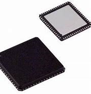
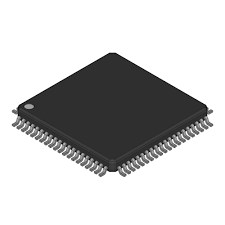
128KB 128K x 8 FLASH ARM® Cortex®-M4 32-Bit Microcontroller STM32F3 Series STM32F302 48 Pin 72MHz 3.3V 48-LQFP


128KB 128K x 8 FLASH ARM® Cortex®-M4 32-Bit Microcontroller STM32F3 Series STM32F302 48 Pin 72MHz 3.3V 48-LQFP
Learn how to integrate the STM32F302CBT6 microcontroller into your 2025 projects with step-by-step guidance on setup, configuration, and debugging.
Product Introduction
The STM32F302CBT6 is a high-performance microcontroller designed to meet the demands of modern embedded systems. Powered by an ARM Cortex-M4 core running at up to 72 MHz, it provides the processing power needed for complex applications. You can rely on its 256 Kbytes of Flash memory and 40 Kbytes of SRAM for efficient data handling and storage.
This microcontroller is ideal for 2025 projects due to its low power consumption and advanced power-saving modes. Its extensive connectivity options, including I2C, SPI, USART, and USB, make it perfect for IoT and embedded systems. Operating in temperatures from -40 to +105 °C, it ensures reliability in various environments.
When you choose the STM32F302CBT6, you gain access to a versatile platform that supports innovation and performance optimization in your designs.
Understanding STM32F302CBT6
Key Specifications of STM32F302CBT6
The STM32F302CBT6 microcontroller offers a robust set of specifications that make it a standout choice for embedded systems. Its ARM Cortex-M4 core delivers reliable performance at 72 MHz, ensuring smooth operation for demanding applications. The microcontroller includes 128 kB of Flash memory and 32 kB of RAM, providing ample space for code and data storage.
Here’s a quick overview of its key specifications:
| Specification | Details |
|---|---|
| Package | LQFP 48 7x7x1.4 mm |
| Memory Size | 128 kB |
| RAM Size | 32K x 8 |
| Core Processor | ARM Cortex-M4 |
| Operating Voltage | 2V~3.6V |
| Number of I/O Pins | 37 |
| ADC Channels | 8 |
| PWM Channels | 6 |
| Frequency | 72 MHz |
| Connectivity | CAN, I2C, I2S, IrDA, LIN, SPI, UART, USART, USB |
This microcontroller product line is designed to handle a wide range of applications, from IoT devices to industrial automation.
Features and Advantages of STM32 Microcontrollers
STM32 series microcontrollers are known for their versatility and performance. They combine advanced processing capabilities with energy efficiency, making them suitable for various applications.
Some key advantages include:
Low Power Consumption: Ideal for battery-powered devices, STM32 microcontrollers offer power-saving modes to extend device life.
Rich Peripheral Set: You can access features like timers, ADCs, and communication interfaces such as SPI and USB.
Cost-Effectiveness: STM32 microcontrollers provide high performance at an affordable price, making them accessible for both hobbyists and professionals.
Development Tools: A wide range of tools, including STM32CubeMX and STM32CubeIDE, simplifies programming and debugging.
The STM32F302CBT6 stands out in the STM32 series microcontrollers for its balance of performance and affordability.
Applications of STM32F302CBT6 in Embedded Systems and IoT
The STM32F302CBT6 microcontroller is a versatile solution for many applications. Its processing power and connectivity options make it a popular choice for IoT devices, where real-time data processing and communication are essential.
Here are some common applications:
Industrial Automation: Use it to control motors, sensors, and other industrial equipment.
Smart Home Devices: Build smart thermostats, lighting systems, or security cameras.
Wearable Technology: Its low power consumption makes it perfect for fitness trackers and health monitors.
Robotics: Leverage its PWM channels and ADCs for precise motor control and sensor integration.
Automotive Systems: Implement it in CAN-based communication systems for vehicles.
The STM32F302CBT6 microcontroller empowers you to create innovative designs across diverse fields.
Preparing for STM32F302CBT6 Integration
Required Tools and Software for STM32 Projects
To begin your STM32F302CBT6 integration, you need the right tools and software. These resources simplify development and ensure smooth project execution. Start by installing STM32CubeIDE, an all-in-one development environment that supports coding, debugging, and compiling. STM32CubeMX is another essential tool. It helps you configure the microcontroller's peripherals and generate initialization code.
For advanced debugging, consider tools like ST-Link/V2 or J-Link. These hardware debuggers allow you to monitor and troubleshoot your code in real time. If you prefer a different IDE, Keil MDK and IAR Embedded Workbench are excellent alternatives. Both offer robust features for embedded programming.
Additionally, familiarize yourself with C/C++ programming. These languages are the backbone of STM32 projects. Online tutorials and forums can help you sharpen your skills. By combining the right software tools with programming knowledge, you’ll set a strong foundation for your STM32 projects.
Essential Hardware Components for STM32F302CBT6
Hardware plays a crucial role in STM32F302CBT6 integration. You’ll need a reliable power source, such as a USB cable or external battery, to supply the microcontroller. Breadboards and jumper wires are essential for prototyping and connecting components.
Include sensors and actuators based on your project requirements. For example, temperature sensors are ideal for IoT applications, while motors suit robotics projects. Don’t forget passive components like resistors and capacitors. These ensure stable operation and protect your microcontroller from voltage fluctuations.
A hardware debugger, such as ST-Link/V2, is indispensable for testing and troubleshooting. It connects directly to the STM32F302CBT6 and provides real-time insights into your program’s behavior. With these components, you’ll have everything you need to bring your ideas to life.
Choosing Development Boards and Starter Kits
Selecting the right development board is key to successful STM32 integration. STM32 Nucleo boards are popular choices. They offer a balance of performance and affordability, making them suitable for beginners and professionals alike. Evaluate your project needs, such as processing power, memory capacity, and peripheral requirements, before choosing a board.
Setting up your development environment is equally important. Install STM32CubeIDE or Keil MDK to streamline coding and debugging. Master embedded programming techniques, including interrupt handling and peripheral management, to maximize your board’s capabilities.
Leverage online resources and communities for support. Forums like ST Community and platforms like GitHub provide valuable insights and code examples. Stay updated with industry trends by following blogs and attending conferences. These steps will help you make the most of your STM32 development board and starter kit.
Step-by-Step STM32F302CBT6 Integration Process
Setting Up the Development Environment
To start working with the STM32F302CBT6, you need to set up a development environment that supports efficient programming and debugging. Begin by downloading and installing STM32CubeIDE, which combines coding, compiling, and debugging tools into one platform. This software simplifies the development process and ensures compatibility with STM32 microcontrollers.
Next, install STM32CubeMX, a graphical configuration tool that helps you set up the microcontroller's peripherals. This tool generates initialization code based on your project requirements, saving you time and effort.
You also need a hardware debugger like ST-Link/V2. This device connects your computer to the STM32F302CBT6 and allows you to test and debug your code in real time. Ensure your computer has the necessary drivers installed for the debugger to function correctly.
Tip: Keep your workspace organized by labeling cables and components. This practice reduces errors during setup and testing.
Once your tools are ready, connect the STM32F302CBT6 to your computer using a USB cable or development board. Verify the connection by checking the device manager or running a simple test program. With your development environment set up, you’re ready to configure the microcontroller for your project.
Configuring STM32F302CBT6 with STM32CubeMX
STM32CubeMX simplifies the configuration process for the STM32F302CBT6. Open the tool and create a new project. Select the STM32F302CBT6 microcontroller from the list of available devices. The tool will display a graphical representation of the microcontroller's pins and peripherals.
Start by configuring the clock settings. Choose the appropriate clock source, such as the internal oscillator or an external crystal, based on your project needs. Adjust the clock speed to optimize performance without exceeding the microcontroller's limits.
Next, enable the peripherals required for your application. For example, activate the ADC channels for sensor inputs or the PWM channels for motor control. Use the graphical interface to assign pins to specific functions, ensuring there are no conflicts.
After configuring the peripherals, generate the initialization code. STM32CubeMX will create a set of files that include the necessary setup for your microcontroller. Import these files into STM32CubeIDE to begin coding.
Note: Double-check your pin assignments and peripheral settings before generating the code. Incorrect configurations can lead to errors during testing.
Writing and Compiling Code for STM32 Microcontrollers
Writing code for STM32 microcontrollers involves using C or C++ programming languages. Start by opening STM32CubeIDE and importing the initialization code generated by STM32CubeMX. This code provides a foundation for your project, including basic setup for peripherals and system clocks.
Write your application code in the main.c file. Use the HAL (Hardware Abstraction Layer) library to interact with the microcontroller's peripherals. For example, use HAL_GPIO_WritePin to control digital outputs or HAL_ADC_Start to read analog inputs.
Compile your code using the built-in compiler in STM32CubeIDE. The tool will check for syntax errors and generate a binary file that can be uploaded to the microcontroller. If errors occur, review your code and ensure all functions and variables are correctly defined.
Tip: Break your code into smaller functions to improve readability and simplify debugging.
Once the code compiles successfully, you can proceed to upload it to the STM32F302CBT6 and test its functionality. Writing and compiling code is an iterative process, so refine your program as needed to achieve the desired results.
Debugging and Testing STM32F302CBT6 Programs
Testing and debugging are essential steps in ensuring your STM32F302CBT6 program works as intended. Begin by verifying the basic functionality of your code. Use the debugging tools available in STM32CubeIDE to step through your program line by line. This process helps you identify logical errors and confirm that each function behaves as expected.
To debug hardware-related issues, connect your STM32F302CBT6 microcontroller to a hardware debugger like ST-Link/V2. This device allows you to monitor the microcontroller’s behavior in real time. Check the status of GPIO pins, peripheral registers, and memory locations using the debugger interface.
Here’s a simple checklist for debugging:
Verify Connections: Ensure all hardware components are properly connected. Loose wires or incorrect pin assignments can cause unexpected behavior.
Check Peripheral Settings: Confirm that the peripherals are configured correctly in STM32CubeMX. Misconfigured settings can lead to communication errors.
Monitor Variables: Use breakpoints to pause your program and inspect variable values. This technique helps you pinpoint issues in your code logic.
Test Incrementally: Test small sections of your code before integrating them into the main program. This approach simplifies debugging and reduces errors.
Tip: Keep a log of the changes you make during debugging. This practice helps you track progress and avoid repeating mistakes.
Once you’ve resolved all issues, run your program multiple times to ensure consistent performance. Testing under different conditions, such as varying input values or environmental factors, can reveal hidden bugs.
Uploading Code to the STM32F302CBT6 Microcontroller
Uploading your code to the STM32F302CBT6 is the final step in the integration process. Start by connecting the microcontroller to your computer using a USB cable or a development board. Ensure the ST-Link/V2 debugger is properly attached to facilitate communication between your computer and the microcontroller.
Open STM32CubeIDE and select the “Run” or “Debug” option. The IDE will compile your code and upload the binary file to the microcontroller. During this process, watch for any error messages that may indicate issues with the code or hardware setup.
If you encounter upload errors, check the following:
Power Supply: Verify that the microcontroller is receiving adequate power.
Driver Installation: Ensure the ST-Link/V2 drivers are installed and up to date.
Connection Integrity: Inspect the USB cable and debugger connections for damage or loose fittings.
After successfully uploading the code, test the microcontroller to confirm it executes the program as intended. For example, if your code controls an LED, check whether the LED blinks according to your instructions.
Note: Always use the latest firmware for your STM32 development tools. Updated firmware improves compatibility and reduces upload errors.
You can also use alternative methods like bootloader-based programming for uploading code. This method is useful when you want to update the microcontroller’s firmware without a debugger.
By following these steps, you’ll ensure a smooth upload process and prepare your STM32F302CBT6 microcontroller for real-world applications.
Best Practices for STM32F302CBT6 Integration
Optimizing STM32 Microcontroller Performance
To get the best performance from your stm32 microcontroller, focus on efficient resource utilization. Start by optimizing your clock configuration. Use STM32CubeMX to select the lowest clock speed that meets your application's needs. This reduces power consumption and heat generation.
Efficient memory management is another key factor. Avoid unnecessary memory allocations in your code. Use static memory allocation whenever possible. This approach minimizes runtime errors and improves execution speed.
You should also leverage the stm32's low-power modes. These modes allow the microcontroller to conserve energy during idle periods. For example, use the "Stop Mode" for battery-powered devices to extend their operational life.
Finally, test your design under real-world conditions. Simulate different workloads and environmental factors to ensure consistent performance.
Avoiding Common Mistakes in STM32 Projects
Mistakes during stm32 pcb design can lead to project delays or failures. One common error is improper pin configuration. Always double-check your pin assignments in STM32CubeMX before generating code.
Another frequent issue is neglecting power supply requirements. Ensure your microcontroller receives a stable voltage within its operating range. Use capacitors to filter out noise and prevent voltage fluctuations.
Overlooking debugging tools is another pitfall. Use hardware debuggers like ST-Link/V2 to identify and fix issues early in the development process.
Lastly, avoid rushing through the testing phase. Test each module of your design separately before integrating them. This approach simplifies troubleshooting and ensures reliability.
Ensuring Reliability in STM32F302CBT6 Designs
Reliability is crucial in stm32 pcb design, especially for long-term applications. Start by selecting high-quality components. Use resistors, capacitors, and connectors that meet industry standards.
Design your PCB layout with care. Keep signal traces short and separate high-frequency signals from sensitive analog lines. This reduces electromagnetic interference and improves signal integrity.
Implement error-handling routines in your code. For example, add checks to handle communication failures or unexpected inputs. These routines make your design more robust.
Finally, conduct thorough testing. Use stress tests to evaluate your design's performance under extreme conditions. This ensures your stm32f302cbt6-based project remains reliable in real-world scenarios.
Troubleshooting STM32F302CBT6 Integration Issues
Debugging Hardware Connectivity Problems
Hardware connectivity issues can disrupt your STM32F302CBT6 project. To identify and resolve these problems, start by inspecting the physical connections. Check the USB cable, jumper wires, and connectors for damage or loose fittings. Ensure each pin is correctly aligned with its corresponding header on the development board.
Use a multimeter to verify electrical continuity. Measure the voltage at critical points, such as the power supply pins and GPIO pins. If the readings fall outside the expected range, adjust the power source or replace faulty components.
Next, examine the PCB layout. Look for overlapping traces or soldering errors that could cause short circuits. Keep signal traces short and separate high-frequency lines from sensitive analog signals to reduce interference.
If the microcontroller fails to respond, test the ST-Link/V2 debugger connection. Confirm that the debugger drivers are installed and up to date. Use STM32CubeIDE to run a simple test program, such as toggling an LED, to verify communication between your computer and the microcontroller.
Tip: Label your cables and components during setup. This practice minimizes confusion and speeds up troubleshooting.
Resolving Software Configuration Errors
Software configuration errors often stem from incorrect settings in STM32CubeMX. Begin by reviewing your project configuration. Check the clock source and speed settings to ensure they match your design requirements. Misconfigured clocks can lead to unstable operation or peripheral failures.
Verify the peripheral settings. For example, confirm that ADC channels are enabled for sensor inputs or PWM channels are activated for motor control. Use the graphical interface in STM32CubeMX to check pin assignments and avoid conflicts.
Revisit the initialization code generated by STM32CubeMX. Look for missing or incorrect function calls. If you suspect an error, compare the code against the STM32 reference manual to ensure compliance with the microcontroller's specifications.
When debugging software issues, use breakpoints in STM32CubeIDE. Pause the program at critical points to inspect variable values and peripheral registers. This technique helps you pinpoint errors in your code logic.
Note: Always save your STM32CubeMX project file before making changes. This ensures you can revert to a previous configuration if needed.
Addressing Programming and Compilation Issues
Programming and compilation errors can prevent your STM32F302CBT6 project from functioning correctly. Start by checking your code for syntax errors. Use STM32CubeIDE's built-in compiler to identify issues and correct them. Pay attention to variable declarations, function calls, and loop structures.
Divide your code into smaller functions. This approach simplifies debugging and makes your program easier to understand. Test each function independently before integrating it into the main program.
If the compiler generates warnings, address them promptly. Warnings often indicate potential issues that could affect your design's reliability. For example, unused variables or implicit type conversions can lead to unexpected behavior.
When uploading code to the microcontroller, ensure the ST-Link/V2 debugger is properly connected. If upload errors occur, check the power supply and USB cable for faults. Update the debugger firmware to improve compatibility with STM32CubeIDE.
Tip: Use version control software like Git to track changes in your code. This practice helps you identify the source of errors and revert to a stable version if necessary.
Integrating the STM32F302CBT6 microcontroller into your projects involves a clear and structured process. You start by setting up the development environment, configuring the microcontroller with STM32CubeMX, and writing efficient code. Testing and debugging ensure your design performs reliably in real-world scenarios.
By leveraging the STM32F302CBT6’s advanced features, you can create innovative designs that stand out. Its low power consumption, rich peripheral set, and robust performance make it a perfect choice for modern applications.
Take the first step today. With the right tools and knowledge, you can bring your ideas to life and build designs that inspire.
FAQ
What makes the STM32F302CBT6 suitable for IoT projects?
The STM32F302CBT6 offers low power consumption, multiple communication interfaces (like I2C, SPI, and USB), and robust performance. These features make it ideal for IoT devices that require efficient data processing and reliable connectivity.
Can you use STM32CubeMX without prior experience?
Yes, STM32CubeMX is beginner-friendly. Its graphical interface simplifies peripheral configuration and code generation. You can follow tutorials or guides to learn the basics quickly.
How do you debug STM32F302CBT6 programs effectively?
Use STM32CubeIDE’s debugging tools to step through your code. Combine this with a hardware debugger like ST-Link/V2 to monitor real-time behavior. Breakpoints and variable monitoring help identify issues efficiently.
What is the best way to power the STM32F302CBT6?
You can power the STM32F302CBT6 using a USB cable, external battery, or regulated power supply. Ensure the voltage stays within the 2V–3.6V range to avoid damage.
Do you need advanced programming skills to work with STM32 microcontrollers?
No, basic knowledge of C/C++ is enough to start. STM32CubeIDE and STM32CubeMX simplify the process. Online resources and community forums provide additional support for beginners.
Specifications
- TypeParameter
- Lifecycle Status
Lifecycle Status refers to the current stage of an electronic component in its product life cycle, indicating whether it is active, obsolete, or transitioning between these states. An active status means the component is in production and available for purchase. An obsolete status indicates that the component is no longer being manufactured or supported, and manufacturers typically provide a limited time frame for support. Understanding the lifecycle status is crucial for design engineers to ensure continuity and reliability in their projects.
ACTIVE (Last Updated: 2 weeks ago) - Factory Lead Time10 Weeks
- Contact Plating
Contact plating (finish) provides corrosion protection for base metals and optimizes the mechanical and electrical properties of the contact interfaces.
Gold - Mounting Type
The "Mounting Type" in electronic components refers to the method used to attach or connect a component to a circuit board or other substrate, such as through-hole, surface-mount, or panel mount.
Surface Mount - Package / Case
refers to the protective housing that encases an electronic component, providing mechanical support, electrical connections, and thermal management.
48-LQFP - Surface Mount
having leads that are designed to be soldered on the side of a circuit board that the body of the component is mounted on.
YES - Number of Pins48
- Data ConvertersA/D 9x12b; D/A 1x12b
- Number of I/Os37
- Watchdog TimersYes
- Operating Temperature
The operating temperature is the range of ambient temperature within which a power supply, or any other electrical equipment, operate in. This ranges from a minimum operating temperature, to a peak or maximum operating temperature, outside which, the power supply may fail.
-40°C~85°C TA - Packaging
Semiconductor package is a carrier / shell used to contain and cover one or more semiconductor components or integrated circuits. The material of the shell can be metal, plastic, glass or ceramic.
Tray - Series
In electronic components, the "Series" refers to a group of products that share similar characteristics, designs, or functionalities, often produced by the same manufacturer. These components within a series typically have common specifications but may vary in terms of voltage, power, or packaging to meet different application needs. The series name helps identify and differentiate between various product lines within a manufacturer's catalog.
STM32F3 - JESD-609 Code
The "JESD-609 Code" in electronic components refers to a standardized marking code that indicates the lead-free solder composition and finish of electronic components for compliance with environmental regulations.
e3 - Part Status
Parts can have many statuses as they progress through the configuration, analysis, review, and approval stages.
Active - Moisture Sensitivity Level (MSL)
Moisture Sensitivity Level (MSL) is a standardized rating that indicates the susceptibility of electronic components, particularly semiconductors, to moisture-induced damage during storage and the soldering process, defining the allowable exposure time to ambient conditions before they require special handling or baking to prevent failures
3 (168 Hours) - Number of Terminations48
- Terminal Finish
Terminal Finish refers to the surface treatment applied to the terminals or leads of electronic components to enhance their performance and longevity. It can improve solderability, corrosion resistance, and overall reliability of the connection in electronic assemblies. Common finishes include nickel, gold, and tin, each possessing distinct properties suitable for various applications. The choice of terminal finish can significantly impact the durability and effectiveness of electronic devices.
Matte Tin (Sn) - Terminal Position
In electronic components, the term "Terminal Position" refers to the physical location of the connection points on the component where external electrical connections can be made. These connection points, known as terminals, are typically used to attach wires, leads, or other components to the main body of the electronic component. The terminal position is important for ensuring proper connectivity and functionality of the component within a circuit. It is often specified in technical datasheets or component specifications to help designers and engineers understand how to properly integrate the component into their circuit designs.
QUAD - Terminal Form
Occurring at or forming the end of a series, succession, or the like; closing; concluding.
GULL WING - Supply Voltage
Supply voltage refers to the electrical potential difference provided to an electronic component or circuit. It is crucial for the proper operation of devices, as it powers their functions and determines performance characteristics. The supply voltage must be within specified limits to ensure reliability and prevent damage to components. Different electronic devices have specific supply voltage requirements, which can vary widely depending on their design and intended application.
3.3V - Terminal Pitch
The center distance from one pole to the next.
0.5mm - Frequency
In electronic components, the parameter "Frequency" refers to the rate at which a signal oscillates or cycles within a given period of time. It is typically measured in Hertz (Hz) and represents how many times a signal completes a full cycle in one second. Frequency is a crucial aspect in electronic components as it determines the behavior and performance of various devices such as oscillators, filters, and communication systems. Understanding the frequency characteristics of components is essential for designing and analyzing electronic circuits to ensure proper functionality and compatibility with other components in a system.
72MHz - Base Part Number
The "Base Part Number" (BPN) in electronic components serves a similar purpose to the "Base Product Number." It refers to the primary identifier for a component that captures the essential characteristics shared by a group of similar components. The BPN provides a fundamental way to reference a family or series of components without specifying all the variations and specific details.
STM32F302 - Supply Voltage-Min (Vsup)
The parameter "Supply Voltage-Min (Vsup)" in electronic components refers to the minimum voltage level required for the component to operate within its specified performance range. This parameter indicates the lowest voltage that can be safely applied to the component without risking damage or malfunction. It is crucial to ensure that the supply voltage provided to the component meets or exceeds this minimum value to ensure proper functionality and reliability. Failure to adhere to the specified minimum supply voltage may result in erratic behavior, reduced performance, or even permanent damage to the component.
2V - Interface
In electronic components, the term "Interface" refers to the point at which two different systems, devices, or components connect and interact with each other. It can involve physical connections such as ports, connectors, or cables, as well as communication protocols and standards that facilitate the exchange of data or signals between the connected entities. The interface serves as a bridge that enables seamless communication and interoperability between different parts of a system or between different systems altogether. Designing a reliable and efficient interface is crucial in ensuring proper functionality and performance of electronic components and systems.
CAN, I2C, I2S, IrDA, LIN, SPI, UART, USART, USB - Memory Size
The memory capacity is the amount of data a device can store at any given time in its memory.
128kB - Oscillator Type
Wien Bridge Oscillator; RC Phase Shift Oscillator; Hartley Oscillator; Voltage Controlled Oscillator; Colpitts Oscillator; Clapp Oscillators; Crystal Oscillators; Armstrong Oscillator.
Internal - RAM Size
RAM size refers to the amount of random access memory (RAM) available in an electronic component, such as a computer or smartphone. RAM is a type of volatile memory that stores data and instructions that are actively being used by the device's processor. The RAM size is typically measured in gigabytes (GB) and determines how much data the device can store and access quickly for processing. A larger RAM size allows for smoother multitasking, faster loading times, and better overall performance of the electronic component. It is an important factor to consider when choosing a device, especially for tasks that require a lot of memory, such as gaming, video editing, or running multiple applications simultaneously.
32K x 8 - Voltage - Supply (Vcc/Vdd)
Voltage - Supply (Vcc/Vdd) is a key parameter in electronic components that specifies the voltage level required for the proper operation of the device. It represents the power supply voltage that needs to be provided to the component for it to function correctly. This parameter is crucial as supplying the component with the correct voltage ensures that it operates within its specified limits and performance characteristics. It is typically expressed in volts (V) and is an essential consideration when designing and using electronic circuits to prevent damage and ensure reliable operation.
2V~3.6V - uPs/uCs/Peripheral ICs Type
The parameter "uPs/uCs/Peripheral ICs Type" refers to the classification of various integrated circuits used in electronic devices. It encompasses microprocessors (uPs), microcontrollers (uCs), and peripheral integrated circuits that provide additional functionalities. This classification helps in identifying the specific type of chip used for processing tasks, controlling hardware, or interfacing with other components in a system. Understanding this parameter is essential for selecting the appropriate electronic components for a given application.
MICROCONTROLLER, RISC - Core Processor
The term "Core Processor" typically refers to the central processing unit (CPU) of a computer or electronic device. It is the primary component responsible for executing instructions, performing calculations, and managing data within the system. The core processor is often considered the brain of the device, as it controls the overall operation and functionality. It is crucial for determining the speed and performance capabilities of the device, as well as its ability to handle various tasks and applications efficiently. In modern devices, core processors can have multiple cores, allowing for parallel processing and improved multitasking capabilities.
ARM® Cortex®-M4 - Peripherals
In the context of electronic components, "Peripherals" refer to devices or components that are connected to a main system or device to enhance its functionality or provide additional features. These peripherals can include input devices such as keyboards, mice, and touchscreens, as well as output devices like monitors, printers, and speakers. Other examples of peripherals include external storage devices, network adapters, and cameras. Essentially, peripherals are external devices that expand the capabilities of a main electronic system or device.
DMA, I2S, POR, PWM, WDT - Program Memory Type
Program memory typically refers to flash memory when it is used to hold the program (instructions). Program memory may also refer to a hard drive or solid state drive (SSD). Contrast with data memory.
FLASH - Core Size
Core size in electronic components refers to the physical dimensions of the core material used in devices such as inductors and transformers. The core size directly impacts the performance characteristics of the component, including its inductance, saturation current, and frequency response. A larger core size typically allows for higher power handling capabilities and lower core losses, while a smaller core size may result in a more compact design but with limitations on power handling and efficiency. Designers must carefully select the core size based on the specific requirements of the application to achieve optimal performance and efficiency.
32-Bit - Program Memory Size
Program Memory Size refers to the amount of memory available in an electronic component, such as a microcontroller or microprocessor, that is used to store program instructions. This memory is non-volatile, meaning that the data stored in it is retained even when the power is turned off. The program memory size determines the maximum amount of code that can be stored and executed by the electronic component. It is an important parameter to consider when selecting a component for a specific application, as insufficient program memory size may limit the functionality or performance of the device.
128KB 128K x 8 - Connectivity
In electronic components, "Connectivity" refers to the ability of a component to establish and maintain connections with other components or devices within a circuit. It is a crucial parameter that determines how easily signals can be transmitted between different parts of a circuit. Connectivity can be influenced by factors such as the number of input and output ports, the type of connectors used, and the overall design of the component. Components with good connectivity are essential for ensuring reliable and efficient operation of electronic systems.
CANbus, I2C, IrDA, LINbus, SPI, UART/USART, USB - Bit Size
In electronic components, "Bit Size" refers to the number of bits that can be processed or stored by a particular component. A bit is the smallest unit of data in computing and can have a value of either 0 or 1. The Bit Size parameter is commonly used to describe the capacity or performance of components such as microprocessors, memory modules, and data buses. A larger Bit Size generally indicates a higher processing capability or storage capacity, allowing for more complex operations and larger amounts of data to be handled efficiently. It is an important specification to consider when selecting electronic components for specific applications that require certain levels of performance and data processing capabilities.
32 - Has ADC
Has ADC refers to the presence of an Analog-to-Digital Converter (ADC) in an electronic component. An ADC is a crucial component in many electronic devices as it converts analog signals, such as voltage or current, into digital data that can be processed by a digital system. Having an ADC allows the electronic component to interface with analog signals and convert them into a format that can be manipulated and analyzed digitally. This parameter is important for applications where analog signals need to be converted into digital form for further processing or control.
YES - DMA Channels
DMA (Direct Memory Access) Channels are a feature found in electronic components such as microcontrollers, microprocessors, and peripheral devices. DMA Channels allow data to be transferred directly between peripherals and memory without involving the CPU, thereby reducing the burden on the CPU and improving overall system performance. Each DMA Channel is typically assigned to a specific peripheral device or memory region, enabling efficient data transfer operations. The number of DMA Channels available in a system determines the concurrent data transfer capabilities and can vary depending on the specific hardware design. Overall, DMA Channels play a crucial role in optimizing data transfer efficiency and system performance in electronic devices.
YES - Data Bus Width
The data bus width in electronic components refers to the number of bits that can be transferred simultaneously between the processor and memory. It determines the amount of data that can be processed and transferred in a single operation. A wider data bus allows for faster data transfer speeds and improved overall performance of the electronic device. Common data bus widths include 8-bit, 16-bit, 32-bit, and 64-bit, with higher numbers indicating a larger capacity for data transfer. The data bus width is an important specification to consider when evaluating the speed and efficiency of a computer system or other electronic device.
32b - Core Architecture
In electronic components, the term "Core Architecture" refers to the fundamental design and structure of the component's internal circuitry. It encompasses the arrangement of key components, such as processors, memory units, and input/output interfaces, within the device. The core architecture plays a crucial role in determining the component's performance, power efficiency, and overall capabilities. Different core architectures are optimized for specific applications and requirements, such as high-speed processing, low power consumption, or specialized functions. Understanding the core architecture of electronic components is essential for engineers and designers to select the most suitable components for their projects.
ARM - CPU Family
CPU Family refers to a classification of microprocessors that share a common architecture and design traits. It signifies a group of processors that are typically produced by the same manufacturer and have similar functionality and features. The CPU Family can encompass various models that may differ in performance, power consumption, and specific capabilities but retain a unified core design, allowing for compatibility with software and hardware. This classification helps users and developers to understand the performance characteristics and upgrade pathways of different CPU models within the same family.
CORTEX-M4F - Number of ADC Channels8
- Number of PWM Channels6
- Number of I2C Channels2
- Number of SPI Channels3
- Number of USB Channels1
- Height1.45mm
- Length7.2mm
- Width7.2mm
- REACH SVHC
The parameter "REACH SVHC" in electronic components refers to the compliance with the Registration, Evaluation, Authorization, and Restriction of Chemicals (REACH) regulation regarding Substances of Very High Concern (SVHC). SVHCs are substances that may have serious effects on human health or the environment, and their use is regulated under REACH to ensure their safe handling and minimize their impact.Manufacturers of electronic components need to declare if their products contain any SVHCs above a certain threshold concentration and provide information on the safe use of these substances. This information allows customers to make informed decisions about the potential risks associated with using the components and take appropriate measures to mitigate any hazards.Ensuring compliance with REACH SVHC requirements is essential for electronics manufacturers to meet regulatory standards, protect human health and the environment, and maintain transparency in their supply chain. It also demonstrates a commitment to sustainability and responsible manufacturing practices in the electronics industry.
No SVHC - Radiation Hardening
Radiation hardening is the process of making electronic components and circuits resistant to damage or malfunction caused by high levels of ionizing radiation, especially for environments in outer space (especially beyond the low Earth orbit), around nuclear reactors and particle accelerators, or during nuclear accidents or nuclear warfare.
No - RoHS Status
RoHS means “Restriction of Certain Hazardous Substances” in the “Hazardous Substances Directive” in electrical and electronic equipment.
ROHS3 Compliant - Lead Free
Lead Free is a term used to describe electronic components that do not contain lead as part of their composition. Lead is a toxic material that can have harmful effects on human health and the environment, so the electronics industry has been moving towards lead-free components to reduce these risks. Lead-free components are typically made using alternative materials such as silver, copper, and tin. Manufacturers must comply with regulations such as the Restriction of Hazardous Substances (RoHS) directive to ensure that their products are lead-free and environmentally friendly.
Lead Free
Parts with Similar Specs
- ImagePart NumberManufacturerPackage / CaseNumber of PinsCore ArchitectureData Bus WidthNumber of I/OInterfaceMemory SizeSupply VoltageView Compare
![STM32F302CBT6]()
STM32F302CBT6
48-LQFP
48
ARM
32 b
37
CAN, I2C, I2S, IrDA, LIN, SPI, UART, USART, USB
128 kB
3.3 V
![STM32F373CBT6]()
48-LQFP
48
ARM
32 b
34
2-Wire, I2C, I2S, MMC, SPI, UART, USART, USB
128 kB
1.8 V
![STM32F334C6T6]()
48-LQFP
48
ARM
32 b
37
CAN, I2C, IrDA, LIN, SPI, UART, USART
32 kB
3.3 V
![STM32F103CBT6]()
48-LQFP
48
ARM
32 b
37
CAN, I2C, IrDA, LIN, SPI, UART, USART, USB
128 kB
3.3 V
![ATSAM3S2AA-AU]()
48-LQFP
48
ARM
32 b
36
CAN, I2C, I2S, IrDA, LIN, SPI, UART, USART, USB
128 kB
3.3 V


Datasheet PDF
- Datasheets :
 2N2907 Bipolar PNP Transistor: Pinout, Datasheet and Equivalent
20 May 20219610
 IRF3205 Power MOSFET: Pinout, Application and Datasheet
01 September 202128243
 AOZ1280CI 1.2 A Simple Buck Regulator, SOT-23-6 1.5 MHz EZ Buck
12 February 20224234
 PCF8591 A/D and D/A Converter: Datasheet, PCF8591 Raspberry Pi, Interfacing
09 October 20214052
 BMA020 Acceleration Sensor: Features, Specification and Datasheet
14 August 2024716
![FDG6335N N-Channel MOSFET: Diagram, Pinout, and Datasheet [Video&FAQ]](https://res.utmel.com/Images/Article/ed8c0389-8d09-46cf-91fb-43c5dd0cf724.png) FDG6335N N-Channel MOSFET: Diagram, Pinout, and Datasheet [Video&FAQ]
FDG6335N N-Channel MOSFET: Diagram, Pinout, and Datasheet [Video&FAQ]28 April 20222214
 AD9520-0BCPZ Clock Generators: Pinout, Feature, Specification
14 August 2024544
 AD6623ASZ Transmit Signal Processor: Pinout, Specification, Datasheet
25 May 2021567
 BMW CEO: The Car Chip Problem Will Not Be Solved Until 2023
12 April 20225591
 Enhancing Frequency Stability in Modern Distributed Power Systems
21 September 20244235
 Detailed Introduction of the Chip Design Process
21 December 202117565
![Basic Introduction to Digital Filter [Video]](https://res.utmel.com/Images/Article/b0245181-c936-414a-8241-51bf13e7c6b3.jpg) Basic Introduction to Digital Filter [Video]
Basic Introduction to Digital Filter [Video]23 October 20204808
 PMIC - Gate Drivers: A Purpose-Built Integrated Circuit
22 February 20233168
 Multivibrator: Circuits, Types and Application
08 September 202025066
 Arduino Based Gas Leakage Detection
29 August 20239311
 Examining the performance of SiC inverter and DC-DC Converter Systems over Si
21 March 20234793
STMicroelectronics
In Stock: 36000
United States
China
Canada
Japan
Russia
Germany
United Kingdom
Singapore
Italy
Hong Kong(China)
Taiwan(China)
France
Korea
Mexico
Netherlands
Malaysia
Austria
Spain
Switzerland
Poland
Thailand
Vietnam
India
United Arab Emirates
Afghanistan
Åland Islands
Albania
Algeria
American Samoa
Andorra
Angola
Anguilla
Antigua & Barbuda
Argentina
Armenia
Aruba
Australia
Azerbaijan
Bahamas
Bahrain
Bangladesh
Barbados
Belarus
Belgium
Belize
Benin
Bermuda
Bhutan
Bolivia
Bonaire, Sint Eustatius and Saba
Bosnia & Herzegovina
Botswana
Brazil
British Indian Ocean Territory
British Virgin Islands
Brunei
Bulgaria
Burkina Faso
Burundi
Cabo Verde
Cambodia
Cameroon
Cayman Islands
Central African Republic
Chad
Chile
Christmas Island
Cocos (Keeling) Islands
Colombia
Comoros
Congo
Congo (DRC)
Cook Islands
Costa Rica
Côte d’Ivoire
Croatia
Cuba
Curaçao
Cyprus
Czechia
Denmark
Djibouti
Dominica
Dominican Republic
Ecuador
Egypt
El Salvador
Equatorial Guinea
Eritrea
Estonia
Eswatini
Ethiopia
Falkland Islands
Faroe Islands
Fiji
Finland
French Guiana
French Polynesia
Gabon
Gambia
Georgia
Ghana
Gibraltar
Greece
Greenland
Grenada
Guadeloupe
Guam
Guatemala
Guernsey
Guinea
Guinea-Bissau
Guyana
Haiti
Honduras
Hungary
Iceland
Indonesia
Iran
Iraq
Ireland
Isle of Man
Israel
Jamaica
Jersey
Jordan
Kazakhstan
Kenya
Kiribati
Kosovo
Kuwait
Kyrgyzstan
Laos
Latvia
Lebanon
Lesotho
Liberia
Libya
Liechtenstein
Lithuania
Luxembourg
Macao(China)
Madagascar
Malawi
Maldives
Mali
Malta
Marshall Islands
Martinique
Mauritania
Mauritius
Mayotte
Micronesia
Moldova
Monaco
Mongolia
Montenegro
Montserrat
Morocco
Mozambique
Myanmar
Namibia
Nauru
Nepal
New Caledonia
New Zealand
Nicaragua
Niger
Nigeria
Niue
Norfolk Island
North Korea
North Macedonia
Northern Mariana Islands
Norway
Oman
Pakistan
Palau
Palestinian Authority
Panama
Papua New Guinea
Paraguay
Peru
Philippines
Pitcairn Islands
Portugal
Puerto Rico
Qatar
Réunion
Romania
Rwanda
Samoa
San Marino
São Tomé & Príncipe
Saudi Arabia
Senegal
Serbia
Seychelles
Sierra Leone
Sint Maarten
Slovakia
Slovenia
Solomon Islands
Somalia
South Africa
South Sudan
Sri Lanka
St Helena, Ascension, Tristan da Cunha
St. Barthélemy
St. Kitts & Nevis
St. Lucia
St. Martin
St. Pierre & Miquelon
St. Vincent & Grenadines
Sudan
Suriname
Svalbard & Jan Mayen
Sweden
Syria
Tajikistan
Tanzania
Timor-Leste
Togo
Tokelau
Tonga
Trinidad & Tobago
Tunisia
Turkey
Turkmenistan
Turks & Caicos Islands
Tuvalu
U.S. Outlying Islands
U.S. Virgin Islands
Uganda
Ukraine
Uruguay
Uzbekistan
Vanuatu
Vatican City
Venezuela
Wallis & Futuna
Yemen
Zambia
Zimbabwe
![STM32F103RBT6]() STM32F103RBT6
STM32F103RBT6STMicroelectronics
![STM32F103ZET6]() STM32F103ZET6
STM32F103ZET6STMicroelectronics
![STM32H743IIT6]() STM32H743IIT6
STM32H743IIT6STMicroelectronics
![STM32F407VET6]() STM32F407VET6
STM32F407VET6STMicroelectronics
![STM32F405RGT6]() STM32F405RGT6
STM32F405RGT6STMicroelectronics
![STM32F030C8T6]() STM32F030C8T6
STM32F030C8T6STMicroelectronics
![STM32F100C8T6B]() STM32F100C8T6B
STM32F100C8T6BSTMicroelectronics
![STM32F103VBT6]() STM32F103VBT6
STM32F103VBT6STMicroelectronics
![STM8S003F3U6TR]() STM8S003F3U6TR
STM8S003F3U6TRSTMicroelectronics
![STM32F429ZIT6]() STM32F429ZIT6
STM32F429ZIT6STMicroelectronics


