
 Product
 Brand
Brand Articles
 Tools
Tools
TCRT5000 IR Sensor: Datasheet, Pinout and Circuit


VISHAY - TCRT5000L - OPTICAL SENSOR, REFLECTIVE
The TCRT5000 is an IR sensor unit. This article enforces datasheet, pinout, circuit, applications, and other details about the TCRT5000 sensor. Furthermore, there is a huge range of semiconductors, capacitors, resistors, and ICs in stock. Welcome RFQ!
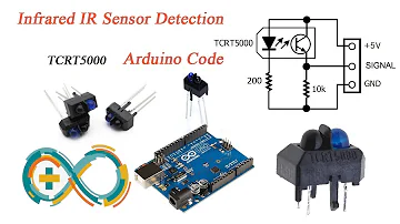
TCRT5000 Sensor IR Infrared Reflective - Arduino Code and Demo
What is TCRT5000 IR Sensor?
The TCRT5000 is an IR sensor including an infrared emitter and phototransistor in a leaded device that blocks visible light. Two mounting clips are included in the package. The long-lead variant is the TCRT5000L.
TCRT5000 Pinout
The following is the pinout diagram for the TCRT5000 IR sensor. This sensor has an infrared transmitter and an infrared receiver, totaling four pins, which are explained below.

TCRT5000 Pinout
| 1 | Collector | The collector of the phototransistor is connected to +5V |
| 2 | Emitter | The emitter of the phototransistor is grounded through a resistor |
| 3 | Anode | The Anode of the photodiode is connected to +5V |
| 4 | Cathode | The Cathode of a photodiode is grounded through a resistor |
TCRT5000 CAD Model
Symbol

TCRT5000 Symbol
Footprint

TCRT5000 Footprint
Specifications
- TypeParameter
- Factory Lead Time32 Weeks
- Contact Plating
Contact plating (finish) provides corrosion protection for base metals and optimizes the mechanical and electrical properties of the contact interfaces.
Silver, Tin - Mount
In electronic components, the term "Mount" typically refers to the method or process of physically attaching or fixing a component onto a circuit board or other electronic device. This can involve soldering, adhesive bonding, or other techniques to secure the component in place. The mounting process is crucial for ensuring proper electrical connections and mechanical stability within the electronic system. Different components may have specific mounting requirements based on their size, shape, and function, and manufacturers provide guidelines for proper mounting procedures to ensure optimal performance and reliability of the electronic device.
Through Hole - Mounting Type
The "Mounting Type" in electronic components refers to the method used to attach or connect a component to a circuit board or other substrate, such as through-hole, surface-mount, or panel mount.
Through Hole - Package / Case
refers to the protective housing that encases an electronic component, providing mechanical support, electrical connections, and thermal management.
PCB Mount - Number of Pins4
- Collector-Emitter Breakdown Voltage70V
- Current-Collector (Ic) (Max)100mA
- Number of Elements1
- Operating Temperature
The operating temperature is the range of ambient temperature within which a power supply, or any other electrical equipment, operate in. This ranges from a minimum operating temperature, to a peak or maximum operating temperature, outside which, the power supply may fail.
-25°C~85°C - Packaging
Semiconductor package is a carrier / shell used to contain and cover one or more semiconductor components or integrated circuits. The material of the shell can be metal, plastic, glass or ceramic.
Tube - Published2009
- Part Status
Parts can have many statuses as they progress through the configuration, analysis, review, and approval stages.
Active - Moisture Sensitivity Level (MSL)
Moisture Sensitivity Level (MSL) is a standardized rating that indicates the susceptibility of electronic components, particularly semiconductors, to moisture-induced damage during storage and the soldering process, defining the allowable exposure time to ambient conditions before they require special handling or baking to prevent failures
1 (Unlimited) - Max Operating Temperature
The Maximum Operating Temperature is the maximum body temperature at which the thermistor is designed to operate for extended periods of time with acceptable stability of its electrical characteristics.
85°C - Min Operating Temperature
The "Min Operating Temperature" parameter in electronic components refers to the lowest temperature at which the component is designed to operate effectively and reliably. This parameter is crucial for ensuring the proper functioning and longevity of the component, as operating below this temperature may lead to performance issues or even damage. Manufacturers specify the minimum operating temperature to provide guidance to users on the environmental conditions in which the component can safely operate. It is important to adhere to this parameter to prevent malfunctions and ensure the overall reliability of the electronic system.
-25°C - Voltage - Rated DC
Voltage - Rated DC is a parameter that specifies the maximum direct current (DC) voltage that an electronic component can safely handle without being damaged. This rating is crucial for ensuring the proper functioning and longevity of the component in a circuit. Exceeding the rated DC voltage can lead to overheating, breakdown, or even permanent damage to the component. It is important to carefully consider this parameter when designing or selecting components for a circuit to prevent any potential issues related to voltage overload.
1.25V - Max Power Dissipation
The maximum power that the MOSFET can dissipate continuously under the specified thermal conditions.
200mW - Output Voltage
Output voltage is a crucial parameter in electronic components that refers to the voltage level produced by the component as a result of its operation. It represents the electrical potential difference between the output terminal of the component and a reference point, typically ground. The output voltage is a key factor in determining the performance and functionality of the component, as it dictates the level of voltage that will be delivered to the connected circuit or load. It is often specified in datasheets and technical specifications to ensure compatibility and proper functioning within a given system.
70V - Output Type
The "Output Type" parameter in electronic components refers to the type of signal or data that is produced by the component as an output. This parameter specifies the nature of the output signal, such as analog or digital, and can also include details about the voltage levels, current levels, frequency, and other characteristics of the output signal. Understanding the output type of a component is crucial for ensuring compatibility with other components in a circuit or system, as well as for determining how the output signal can be utilized or processed further. In summary, the output type parameter provides essential information about the nature of the signal that is generated by the electronic component as its output.
Phototransistor - Number of Channels1
- Power Dissipation
the process by which an electronic or electrical device produces heat (energy loss or waste) as an undesirable derivative of its primary action.
200mW - Forward Current
Current which flows upon application of forward voltage.
60mA - Forward Voltage
the amount of voltage needed to get current to flow across a diode.
1.25V - Collector Emitter Voltage (VCEO)
Collector-Emitter Voltage (VCEO) is a key parameter in electronic components, particularly in transistors. It refers to the maximum voltage that can be applied between the collector and emitter terminals of a transistor while the base terminal is open or not conducting. Exceeding this voltage limit can lead to breakdown and potential damage to the transistor. VCEO is crucial for ensuring the safe and reliable operation of the transistor within its specified limits. Designers must carefully consider VCEO when selecting transistors for a circuit to prevent overvoltage conditions that could compromise the performance and longevity of the component.
70V - Max Collector Current
Max Collector Current is a parameter used to specify the maximum amount of current that can safely flow through the collector terminal of a transistor or other electronic component without causing damage. It is typically expressed in units of amperes (A) and is an important consideration when designing circuits to ensure that the component operates within its safe operating limits. Exceeding the specified max collector current can lead to overheating, degradation of performance, or even permanent damage to the component. Designers must carefully consider this parameter when selecting components and designing circuits to ensure reliable and safe operation.
100mA - Sensing Distance
It is the sensing range for which the sensor can stably detect the standard sensing object even if there is an ambient temperature drift and/or supply voltage fluctuation. (Normally, it is 70 to 80 % of the maximum operation distance.)
0.591 (15mm) - Voltage - Collector Emitter Breakdown (Max)
Voltage - Collector Emitter Breakdown (Max) is a parameter that specifies the maximum voltage that can be applied between the collector and emitter terminals of a transistor or other semiconductor device before it breaks down and allows excessive current to flow. This parameter is crucial for ensuring the safe and reliable operation of the component within its specified limits. Exceeding the maximum breakdown voltage can lead to permanent damage or failure of the device. Designers and engineers must carefully consider this parameter when selecting components for their circuits to prevent potential issues and ensure proper functionality.
70V - Reverse Breakdown Voltage
Reverse Breakdown Voltage is the maximum reverse voltage a semiconductor device can withstand before it starts to conduct heavily in the reverse direction. It is a critical parameter in diodes and other components, indicating the threshold at which the material's insulating properties fail. Beyond this voltage, the device may enter a breakdown region, leading to potential damage if not properly managed. This parameter is essential for ensuring safe operation and reliability in electronic circuits.
5V - Sensing Method
The sensing method in electronic components refers to the technique or mechanism used to detect and measure physical phenomena such as temperature, pressure, light, or motion. This includes a variety of technologies such as resistive, capacitive, inductive, and optical sensing methods. The choice of sensing method affects the accuracy, response time, and application suitability of the electronic component. It plays a crucial role in determining how effectively a device can interact with and interpret its environment.
Reflective - Current - DC Forward (If) (Max)
The parameter "Current - DC Forward (If) (Max)" in electronic components refers to the maximum forward current that can safely pass through the component without causing damage. This parameter is typically specified in datasheets for diodes and LEDs, indicating the maximum current that can flow through the component in the forward direction. Exceeding this maximum current rating can lead to overheating and potentially permanent damage to the component. It is important to ensure that the current flowing through the component does not exceed this specified maximum to maintain proper functionality and reliability.
60mA - Input Current
Input current is a parameter that refers to the amount of electrical current flowing into a specific electronic component or device. It is typically measured in amperes (A) and represents the current required for the component to operate properly. Understanding the input current is important for designing circuits and power supplies, as it helps determine the capacity and compatibility of the components being used. Monitoring the input current also helps ensure that the component is not being overloaded or underpowered, which can affect its performance and longevity.
60mA - Reverse Voltage (DC)
Reverse Voltage (DC) refers to the maximum voltage that an electronic component, typically a semiconductor device like a diode, can withstand in the reverse direction without undergoing breakdown or failure. It indicates the threshold at which the device will start to conduct in reverse, potentially damaging the component. This parameter is crucial for ensuring the reliability and safety of circuits that may experience reverse polarity or unexpected voltage conditions. Exceeding the specified reverse voltage can lead to permanent damage or catastrophic failure of the component.
5V - Height7mm
- Length10.2mm
- Width5.8mm
- REACH SVHC
The parameter "REACH SVHC" in electronic components refers to the compliance with the Registration, Evaluation, Authorization, and Restriction of Chemicals (REACH) regulation regarding Substances of Very High Concern (SVHC). SVHCs are substances that may have serious effects on human health or the environment, and their use is regulated under REACH to ensure their safe handling and minimize their impact.Manufacturers of electronic components need to declare if their products contain any SVHCs above a certain threshold concentration and provide information on the safe use of these substances. This information allows customers to make informed decisions about the potential risks associated with using the components and take appropriate measures to mitigate any hazards.Ensuring compliance with REACH SVHC requirements is essential for electronics manufacturers to meet regulatory standards, protect human health and the environment, and maintain transparency in their supply chain. It also demonstrates a commitment to sustainability and responsible manufacturing practices in the electronics industry.
No SVHC - Radiation Hardening
Radiation hardening is the process of making electronic components and circuits resistant to damage or malfunction caused by high levels of ionizing radiation, especially for environments in outer space (especially beyond the low Earth orbit), around nuclear reactors and particle accelerators, or during nuclear accidents or nuclear warfare.
No - RoHS Status
RoHS means “Restriction of Certain Hazardous Substances” in the “Hazardous Substances Directive” in electrical and electronic equipment.
ROHS3 Compliant - Lead Free
Lead Free is a term used to describe electronic components that do not contain lead as part of their composition. Lead is a toxic material that can have harmful effects on human health and the environment, so the electronics industry has been moving towards lead-free components to reduce these risks. Lead-free components are typically made using alternative materials such as silver, copper, and tin. Manufacturers must comply with regulations such as the Restriction of Hazardous Substances (RoHS) directive to ensure that their products are lead-free and environmentally friendly.
Lead Free
TCRT5000 Features
It is available in a leaded package
The type of detector used is photo-transistor
The Peak operating distance is 2.5 mm.
Collector current ranges from 0.2 mm – 15 mm
The typical o/p current blow test (IC) is 1 mA.
Blocking filter for daylight
The wavelength of the emitter is 950 nm
Infrared sensor including the o/p of transistor
The operating voltage is 5V
The forward current of the diode is 60mA
Output data is analog/digital
The Collector current of the transistor is 100mA
Operating temperature ranges from -25°C to +85°C
TCRT5000 Equivalent
RPR220
Alternatives for TCRT5000
IR Photodiode, IR LED, qtr-1rC, TSOP, GP2Y0A21
TCRT5000 Applications
Position sensor for shaft encoder
Detection of reflective material such as paper, IBM cards, magnetic tapes, etc.
Limit switch for mechanical motions in VCR
General-purpose - wherever the space is limited
Where to Use TCRT5000
The TCRT5000 is used to detect color and distance in this IR reflecting sensor. It emits infrared light and then checks to see if it receives an echo. Because this sensor can detect whether a surface is white or black, it is commonly employed in line following robots and automatic data logging on utility meters.
How to Use TCRT5000
The IR sensor circuit for the TCRT500 is given below. The IR sensor in this circuit consists of a photodiode and a phototransistor, which act as a transmitter and receiver, respectively.

TCRT500 Circuit
A 220R resistor is used to activate the photodiode, while a 10K resistor is used to link the phototransistor to GND. Because the transistor biasing is mostly controlled by the received IR light, the transistor in the circuit does not have a base pin. As a result, the photodiode's infrared light strikes a target and returns to the phototransistor to bias it.
Depending on the application, this IR sensor can be utilized as an analog or digital sensor. The main disadvantages of this sensor are that they are easily affected by environmental variables.
It will not only respond to infrared light utilizing the photodiode, but it will also respond to infrared light from many light sources that are generally available, similar to the phototransistor.
Noise cancellation is usually used within the application to solve this problem. So, using an MCU or MPU's GPIO pin, we can deactivate the photodiode and then verify how much noise the transistor in the sensor is reading before activating the photodiode to calculate the change in values by invalidating the noise present while the photodiode was deactivated.
TCRT5000 Package Dimension


TCRT5000 Package Dimension
TCRT5000 Manufacturer
Vishay, an important partner of Digi-Key, serves as a globally recognized manufacturer famous for its discrete semiconductors and passive electronic components. Their discrete semiconductors include diodes, MOSFETs, optoelectronics, etc and their passive components include resistors, inductors, capacitors, etc. These products are widely used for almost all kinds of electronic devices and equipment in the fields of industrial, computing, automotive, telecommunications, military, aerospace, and medical.
Parts with Similar Specs
- ImagePart NumberManufacturerPackage / CaseNumber of PinsNumber of ChannelsOutput VoltageForward VoltageForward CurrentRadiation HardeningView Compare
![TCRT5000L]()
TCRT5000L
PCB Mount
4
1
70 V
1.25 V
60 mA
No

Datasheet PDF
- Datasheets :
- RohsStatement :
- PCN Assembly/Origin :
What is the use of TCRT5000?
You can use the TCRT5000 to check the presence of a physical object such as detecting a coin in a coin sorting device. It can also be used to check the color of something on a black to white scale. This is a principle a line following robot can utilize.
How do I connect a TCRT5000 to Arduino?
In this instructable, basic circuitry for TCRT 5000 IR sensor and its working is discussed. a major focus of this instructable is on making a program that enables it to remove all kinds of ambient noise. So after using this method IR sensor need not be calibrated for different ambiance conditions.
Where can I find information about TCRT5000 working principle?
The TCRT5000 and TCRT5000L are reflective sensors that include an infrared emitter and phototransistor in a leaded package that blocks visible light. The package includes two mounting clips. TCRT5000L is the long lead version. The TCRT5000 (L) has a compact construction where the emitting light source and the detector are arranged in the same direction to sense the presence of an object by using the reflective IR beam from the object. The detector consists of a phototransistor.
How do I connect a TCRT5000 to a Raspberry Pi?
TCRT5000 line followers are super easy to use! You will need two of these to be able to follow a line. Position the line followers next to each other with a slight gap between them. Your line should sit within this gap. The way this works is quite simple. As your robot stays left or right, either the left or right sensor will move over the black line. When this happens, it will trigger that sensor to go low. Knowing which sensor has gone low allows us to move the robot left or right so that the line remains in between the two sensors.
 TL061 Operational Amplifier: Features, Pinout and Datasheet PDF
30 June 20214773
 LM336 2.5V Regulator Diodes: Datasheet, Reference and Circuit
22 September 20217981
![DS18B20 Temperature Sensor[FAQ+Video]: Circuit, Equivalents,and Pinout](https://res.utmel.com/Images/Article/50daa56f-b3f7-4f8a-8cf2-00186ccb88bd.jpg) DS18B20 Temperature Sensor[FAQ+Video]: Circuit, Equivalents,and Pinout
DS18B20 Temperature Sensor[FAQ+Video]: Circuit, Equivalents,and Pinout17 April 20253954
 EP3C40F484C8N FPGA: Advantages, Challenges, and Project Suitability
07 June 2025409
![CR1025 VS. BR1025 VS. LIR1025 [FAQ]](https://res.utmel.com/Images/Article/7c55cabd-3eb1-4d16-9350-236919e3fd81.jpg) CR1025 VS. BR1025 VS. LIR1025 [FAQ]
CR1025 VS. BR1025 VS. LIR1025 [FAQ]22 July 20221711
 MPX5010DP Transducer: Pinout, Specifications and Datasheet
18 October 20218479
 CR1220 Lithium Coin Battery: Datasheet, Equivalent and CR1220 vs BR1220
29 April 202210373
 Insight into the Zilog Z8 Encore! XP F082A Series Microcontroller: Features, Architecture, and Applications
29 February 2024218
 Introduction to the Types of SDRAM
13 July 202114548
 Meta-Vision for CMOS Image Sensors: Beyond the Human Eye
15 March 20222837
 Comprehensive Analysis of Each Functional Circuit of Switching Power Supply
06 May 20225759
 Cellular IoT Transmit Module for Enhanced Connectivity and Power Efficiency with Extended Battery Life
30 January 20242274
 Designing Application-Specific Integrated Circuits
07 March 20252332
 Beginners Guide to FPGA Design
29 December 20211199
 Random Access Memory: Definition, Types and Working
29 August 202010575
 A brief Analysis of the 555 Timer Circuit and its Project Applications
15 March 20243335
Vishay Semiconductor Opto Division
In Stock
United States
China
Canada
Japan
Russia
Germany
United Kingdom
Singapore
Italy
Hong Kong(China)
Taiwan(China)
France
Korea
Mexico
Netherlands
Malaysia
Austria
Spain
Switzerland
Poland
Thailand
Vietnam
India
United Arab Emirates
Afghanistan
Åland Islands
Albania
Algeria
American Samoa
Andorra
Angola
Anguilla
Antigua & Barbuda
Argentina
Armenia
Aruba
Australia
Azerbaijan
Bahamas
Bahrain
Bangladesh
Barbados
Belarus
Belgium
Belize
Benin
Bermuda
Bhutan
Bolivia
Bonaire, Sint Eustatius and Saba
Bosnia & Herzegovina
Botswana
Brazil
British Indian Ocean Territory
British Virgin Islands
Brunei
Bulgaria
Burkina Faso
Burundi
Cabo Verde
Cambodia
Cameroon
Cayman Islands
Central African Republic
Chad
Chile
Christmas Island
Cocos (Keeling) Islands
Colombia
Comoros
Congo
Congo (DRC)
Cook Islands
Costa Rica
Côte d’Ivoire
Croatia
Cuba
Curaçao
Cyprus
Czechia
Denmark
Djibouti
Dominica
Dominican Republic
Ecuador
Egypt
El Salvador
Equatorial Guinea
Eritrea
Estonia
Eswatini
Ethiopia
Falkland Islands
Faroe Islands
Fiji
Finland
French Guiana
French Polynesia
Gabon
Gambia
Georgia
Ghana
Gibraltar
Greece
Greenland
Grenada
Guadeloupe
Guam
Guatemala
Guernsey
Guinea
Guinea-Bissau
Guyana
Haiti
Honduras
Hungary
Iceland
Indonesia
Iran
Iraq
Ireland
Isle of Man
Israel
Jamaica
Jersey
Jordan
Kazakhstan
Kenya
Kiribati
Kosovo
Kuwait
Kyrgyzstan
Laos
Latvia
Lebanon
Lesotho
Liberia
Libya
Liechtenstein
Lithuania
Luxembourg
Macao(China)
Madagascar
Malawi
Maldives
Mali
Malta
Marshall Islands
Martinique
Mauritania
Mauritius
Mayotte
Micronesia
Moldova
Monaco
Mongolia
Montenegro
Montserrat
Morocco
Mozambique
Myanmar
Namibia
Nauru
Nepal
New Caledonia
New Zealand
Nicaragua
Niger
Nigeria
Niue
Norfolk Island
North Korea
North Macedonia
Northern Mariana Islands
Norway
Oman
Pakistan
Palau
Palestinian Authority
Panama
Papua New Guinea
Paraguay
Peru
Philippines
Pitcairn Islands
Portugal
Puerto Rico
Qatar
Réunion
Romania
Rwanda
Samoa
San Marino
São Tomé & Príncipe
Saudi Arabia
Senegal
Serbia
Seychelles
Sierra Leone
Sint Maarten
Slovakia
Slovenia
Solomon Islands
Somalia
South Africa
South Sudan
Sri Lanka
St Helena, Ascension, Tristan da Cunha
St. Barthélemy
St. Kitts & Nevis
St. Lucia
St. Martin
St. Pierre & Miquelon
St. Vincent & Grenadines
Sudan
Suriname
Svalbard & Jan Mayen
Sweden
Syria
Tajikistan
Tanzania
Timor-Leste
Togo
Tokelau
Tonga
Trinidad & Tobago
Tunisia
Turkey
Turkmenistan
Turks & Caicos Islands
Tuvalu
U.S. Outlying Islands
U.S. Virgin Islands
Uganda
Ukraine
Uruguay
Uzbekistan
Vanuatu
Vatican City
Venezuela
Wallis & Futuna
Yemen
Zambia
Zimbabwe