
 Product
 Brand
Brand Articles
 Tools
Tools
TI INA821 Precision Instrumentation Amplifier: Low-Noise Performance and Design Guide

150pA Instrumentational OP Amps 0.0005μA 4.5V~36V ±2.25V~±18V INA821 8-TSSOP, 8-MSOP (0.118, 3.00mm Width)


150pA Instrumentational OP Amps 0.0005μA 4.5V~36V ±2.25V~±18V INA821 8-TSSOP, 8-MSOP (0.118, 3.00mm Width)
TI INA821: A high-precision, low-power instrumentation amplifier with 35µV max offset and 7nV/√Hz noise. Ideal for medical & industrial designs. View specs & buy.
- Executive Summary: What is the INA821?
- 1. Technical Specifications & Performance Analysis
- 2. Pinout, Package, and Configuration
- 3. Design & Integration Guide (For Engineers & Makers)
- 4. Typical Applications & Use Cases
- 5. Alternatives and Cross-Reference Guide
- 6. Frequently Asked Questions (FAQ)
- 7. Resources
- Specifications
- Datasheet PDF
Executive Summary: What is the INA821?
The INA821 is a high-precision, low-power instrumentation amplifier designed to extract small differential signals in the presence of large common-mode voltages. It is engineered for applications requiring extreme accuracy, such as medical monitoring and industrial sensor interfaces.
Market Position: High-performance precision analog. It balances ultra-low offset voltage with a wide supply range.
Top Features: 35 µV maximum offset voltage, 7 nV/√Hz low noise density, and robust ±40 V input overvoltage protection.
Primary Audience: Design Engineers creating medical instrumentation, industrial process controls, and high-end data acquisition systems.
Supply Status: Active.
1. Technical Specifications & Performance Analysis
The INA821 stands out in the Texas Instruments portfolio for its combination of precision and power efficiency.
1.1 Core Architecture
The INA821 utilizes a classic 3-op-amp instrumentation amplifier architecture, optimized for high common-mode rejection (CMRR) and low input bias current. This architecture is chosen to provide a high-impedance input stage that won't load sensitive sensors, while the internal resistor matching ensures a CMRR of 112 dB (at G=10), effectively "cleaning" signals from noisy environments.
1.2 Key Electrical Characteristics
For procurement and design, the following electrical limits are critical:
Input Offset Voltage: Extremely stable at 35 µV (max), reducing the need for system-level calibration.
Power Consumption: Operates with a maximum supply current of 650 µA, making it suitable for high-density boards or portable equipment.
Voltage Versatility: Supports a wide range from 4.5 V to 36 V for single-supply designs, or ±2.25 V to ±18 V for dual-supply rails.
Dynamic Performance: Offers a 4.7 MHz bandwidth at unity gain, though designers must account for its 2 V/µs slew rate in large-signal applications.
1.3 Interfaces and Connectivity
As an analog component, the INA821 interfaces directly with sensors (Strain Gauges, RTDs, Thermocouples) and outputs a scaled voltage to an Analog-to-Digital Converter (ADC). It features a dedicated Gain (RG) pin for setting the amplification factor with a single external resistor.
2. Pinout, Package, and Configuration
Understanding the physical layout is essential for PCB layout and BOM management.
2.1 Pin Configuration Guide
The INA821 typically comes in an 8-pin configuration:
1. -IN / +IN: Differential analog inputs with ±40V protection.
2. RG (Pins 1 & 8): Connection for the external gain-setting resistor.
3. V- / V+: Power supply pins.
4. REF: Reference pin; used to level-shift the output voltage.
5. OUT: The amplified output signal.
2.2 Naming Convention & Ordering Codes
TI parts use suffixes to denote package type and temperature grade. Common variants include:
INA821IDR: Industrial grade in a standard SOIC-8 package (Tape & Reel).
INA821ID: Industrial grade in SOIC-8 (Tube).
INA821IDGKR: High-density VSSOP-8 package for space-constrained designs.
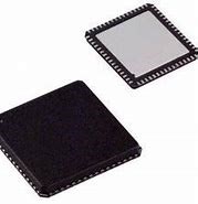
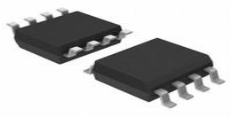
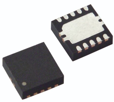
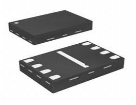
2.3 Available Packages
| Package Type | Dimensions | Common Use Case |
|---|---|---|
| SOIC (D) | 4.9 x 3.9 mm | General industrial, easy hand-soldering/prototyping. |
| VSSOP (DGK) | 3.0 x 3.0 mm | Portable medical devices and compact IoT sensors. |
3. Design & Integration Guide (For Engineers & Makers)
Pro Tip: When designing for high precision, use 0.1% tolerance resistors for the RG pin to maintain the INA821’s inherent accuracy.
3.1 Hardware Implementation
Bypass Capacitors: Place 0.1 µF ceramic capacitors as close as possible to the V+ and V- pins to minimize high-frequency noise.
PCB Layout: Use a solid ground plane. Keep the RG resistor traces short to minimize parasitic capacitance, which can impact stability.
Thermal Management: While the 650 µA current draw is low, ensure the thermal pad (if using specific packages) is soldered to a copper plane to maintain a stable junction temperature.
3.2 Common Design Challenges
Issue: Large Signal Distortion: The 4.7MHz bandwidth is for small signals. Fast edges (like square waves) may distort due to the 2 V/µs slew rate.
Fix: If your application requires high-frequency large signals, consider the AD8421 or limit the input frequency.
Issue: Clipping at High Gain: At G=500, internal nodes can hit supply rails even if the output appears "in range."
Fix: Use TI’s Analog Engineer’s Calculator to check Vcm vs. Vout limits.
Issue: Output Saturation: The output needs ~0.15V of "headroom" from the rails.
Fix: Drive the REF pin with a buffer to shift the signal away from ground in single-supply systems.
4. Typical Applications & Use Cases
Watch Tutorial: INA821
4.1 Real-World Example: Precision Strain Gauge
In industrial weighing scales, the INA821 amplifies the millivolt-level output of a Wheatstone bridge. Because the INA821 has ±40V input protection, it survives accidental wiring errors or transients common in factory environments. Its low noise ensures that the weight measurement remains stable even at high resolutions.
5. Alternatives and Cross-Reference Guide
If the INA821 is out of stock or does not meet specific speed requirements, consider these alternatives:
Direct Replacements:
INA819: Similar footprint, often used for cost-optimization in less demanding specs.
INA818: A lower-power alternative with slightly different noise characteristics.
Better Performance (Speed):
Analog Devices AD8421: Offers significantly higher bandwidth and slew rate for high-speed data acquisition.
Legacy/Standard:
AD8221: The industry-standard instrumentation amplifier; the INA821 is often a modern, lower-noise upgrade.
6. Frequently Asked Questions (FAQ)
Q: What is the difference between INA821 and AD8421?
A: The INA821 is optimized for lower DC offset and power, while the AD8421 provides much higher bandwidth (10 MHz) and slew rate for AC-heavy applications.
Q: Can the INA821 be used in 5V single-supply systems?
A: Yes, it operates down to 4.5V. However, use the REF pin to bias the output to 2.5V to avoid saturation at the ground rail.
Q: Where can I find the INA821 datasheet and CAD models?
A: These are available on the Texas Instruments website and through authorized distributors like Mouser or Digi-Key.
7. Resources
TI Analog Engineer's Calculator: Essential for calculating Vcm vs. Vout.
Evaluation Module: INA821EVM for rapid prototyping.
Application Note: "Precision Instrumentation Amplifier Layout Techniques."
Specifications
Datasheet PDF
- Datasheets :
 STM32F103C6T6A: Feature, Applications, and Datasheet
14 November 20232093
![NE555 VS TLC555[Video] Comparison the differences between them.](https://res.utmel.com/Images/Article/cfe1f243-e88e-4d21-a827-80df4dfc394f.png) NE555 VS TLC555[Video] Comparison the differences between them.
NE555 VS TLC555[Video] Comparison the differences between them.25 April 20229056
 AD9520-0BCPZ Clock Generators: Pinout, Feature, Specification
14 August 2024520
 TJA1051 CAN Transceiver: Features, Equivalent and Datasheet
18 January 202210709
 LTC6752IMS8-2#TRPBF Linear Comparator: Product Overview and Applications
06 March 2024204
 TPS74801DRCR Low-Dropout Linear Regulator: Pinout, Datasheet
16 August 20241109
 MPM-10-24 vs MPM-15-12: A Detailed Comparison
27 May 2025340
 MX25R1635FZUIL0 Flash Memory: Features, Pinout, and Datasheet
24 February 20222187
 Introduction to TTL and CMOS Logic Gate Circuits
24 November 202520404
 Analog-to-Digital Converters (ADCs): Decrypting Resolutions and Sampling Rates
24 February 20224618
 Things You Need to Know about Seven-segment Display
14 October 20216977
 What Makes Rocker Switches Unique
18 July 2025722
 Understanding Power Management Units (PMUs)
06 June 20251082
 An Introduction to DIACs
21 May 20254375
 Inductance Basis: Definition, Structure and Applications
18 April 20228730
 What is fluorescent lamp?
19 October 20213839
Texas Instruments
In Stock: 1300
United States
China
Canada
Japan
Russia
Germany
United Kingdom
Singapore
Italy
Hong Kong(China)
Taiwan(China)
France
Korea
Mexico
Netherlands
Malaysia
Austria
Spain
Switzerland
Poland
Thailand
Vietnam
India
United Arab Emirates
Afghanistan
Åland Islands
Albania
Algeria
American Samoa
Andorra
Angola
Anguilla
Antigua & Barbuda
Argentina
Armenia
Aruba
Australia
Azerbaijan
Bahamas
Bahrain
Bangladesh
Barbados
Belarus
Belgium
Belize
Benin
Bermuda
Bhutan
Bolivia
Bonaire, Sint Eustatius and Saba
Bosnia & Herzegovina
Botswana
Brazil
British Indian Ocean Territory
British Virgin Islands
Brunei
Bulgaria
Burkina Faso
Burundi
Cabo Verde
Cambodia
Cameroon
Cayman Islands
Central African Republic
Chad
Chile
Christmas Island
Cocos (Keeling) Islands
Colombia
Comoros
Congo
Congo (DRC)
Cook Islands
Costa Rica
Côte d’Ivoire
Croatia
Cuba
Curaçao
Cyprus
Czechia
Denmark
Djibouti
Dominica
Dominican Republic
Ecuador
Egypt
El Salvador
Equatorial Guinea
Eritrea
Estonia
Eswatini
Ethiopia
Falkland Islands
Faroe Islands
Fiji
Finland
French Guiana
French Polynesia
Gabon
Gambia
Georgia
Ghana
Gibraltar
Greece
Greenland
Grenada
Guadeloupe
Guam
Guatemala
Guernsey
Guinea
Guinea-Bissau
Guyana
Haiti
Honduras
Hungary
Iceland
Indonesia
Iran
Iraq
Ireland
Isle of Man
Israel
Jamaica
Jersey
Jordan
Kazakhstan
Kenya
Kiribati
Kosovo
Kuwait
Kyrgyzstan
Laos
Latvia
Lebanon
Lesotho
Liberia
Libya
Liechtenstein
Lithuania
Luxembourg
Macao(China)
Madagascar
Malawi
Maldives
Mali
Malta
Marshall Islands
Martinique
Mauritania
Mauritius
Mayotte
Micronesia
Moldova
Monaco
Mongolia
Montenegro
Montserrat
Morocco
Mozambique
Myanmar
Namibia
Nauru
Nepal
New Caledonia
New Zealand
Nicaragua
Niger
Nigeria
Niue
Norfolk Island
North Korea
North Macedonia
Northern Mariana Islands
Norway
Oman
Pakistan
Palau
Palestinian Authority
Panama
Papua New Guinea
Paraguay
Peru
Philippines
Pitcairn Islands
Portugal
Puerto Rico
Qatar
Réunion
Romania
Rwanda
Samoa
San Marino
São Tomé & Príncipe
Saudi Arabia
Senegal
Serbia
Seychelles
Sierra Leone
Sint Maarten
Slovakia
Slovenia
Solomon Islands
Somalia
South Africa
South Sudan
Sri Lanka
St Helena, Ascension, Tristan da Cunha
St. Barthélemy
St. Kitts & Nevis
St. Lucia
St. Martin
St. Pierre & Miquelon
St. Vincent & Grenadines
Sudan
Suriname
Svalbard & Jan Mayen
Sweden
Syria
Tajikistan
Tanzania
Timor-Leste
Togo
Tokelau
Tonga
Trinidad & Tobago
Tunisia
Turkey
Turkmenistan
Turks & Caicos Islands
Tuvalu
U.S. Outlying Islands
U.S. Virgin Islands
Uganda
Ukraine
Uruguay
Uzbekistan
Vanuatu
Vatican City
Venezuela
Wallis & Futuna
Yemen
Zambia
Zimbabwe
![LMV722MX]() LMV722MX
LMV722MXTexas Instruments
![LMC6082AIN]() LMC6082AIN
LMC6082AINTexas Instruments
![RC4558P]() RC4558P
RC4558PTexas Instruments
![LMC6482IMM/NOPB]() LMC6482IMM/NOPB
LMC6482IMM/NOPBTexas Instruments
![LM324MX/NOPB]() LM324MX/NOPB
LM324MX/NOPBTexas Instruments
![LM324AM/NOPB]() LM324AM/NOPB
LM324AM/NOPBTexas Instruments
![LMV324IDR]() LMV324IDR
LMV324IDRTexas Instruments
![LMC7101BIM5/NOPB]() LMC7101BIM5/NOPB
LMC7101BIM5/NOPBTexas Instruments
![TLV2372IDR]() TLV2372IDR
TLV2372IDRTexas Instruments
![NE5532P]() NE5532P
NE5532PTexas Instruments


