
 Product
 Brand
Brand Articles
 Tools
Tools
M24512-DF 512-Kbit serial I²C bus EEPROM: Pinout, Features and Datasheet

Surface Mount Memory IC M24512 512 kb kb 4.4mm mm 5mA mA
Unit Price: $1.343573
Ext Price: $1.34


Surface Mount Memory IC M24512 512 kb kb 4.4mm mm 5mA mA
The M24512-DF is a 512-Kbit I²C-compatible EEPROM (Electrically Erasable PROgrammable Memory) organized as 64 K × 8 bits. The M24512-DF can operate with a supply voltage from 1.7 V to 5.5 V. Furthermore, Huge range of Semiconductors, Capacitors, Resistors and IcS in stock. Welcome RFQ.

What Is EEPROM?
M24512-DF Pinout
The following figure is the diagram of M24512-DF Pinout.

Pinout
M24512-DF CAD Model
The followings are M24512-DF Symbol, Footprint, and 3D Model.

PCB Symbol

PCB Footprint

3D Model
M24512-DF Overview
The M24512 is a 512-Kbit I²C-compatible EEPROM (Electrically Erasable PROgrammable Memory) organized as 64K × 8 bits. The M24512-DF can operate with a supply voltage from 1.7 V to 5.5 V. All these devices operate with a clock frequency of 1 MHz (or less) over an ambient temperature range of -40 °C / +85 °C. The M24512-D offers an additional page, named the Identification Page (128 byte). The Identification Page can be used to store sensitive application parameters which can be (later) permanently locked in Read-only mode.
This article provides you with a basic overview of the M24512-DF 512-Kbit serial I²C bus EEPROM, including its pin descriptions, features and specifications, etc., to help you quickly understand what M24512-DF is.
M24512-DF Features
● Compatible with all I²C bus modes:
◆ 1 MHz
◆ 400 kHz
◆ 100 kHz
● Memory array:
◆ 512 Kbit (64 Kbyte) of EEPROM
◆ Page size: 128 byte
◆ Additional Write lockable page (M24512-D order codes)
● Single supply voltage and high speed:
◆ 1 MHz clock from 1.7 V to 5.5 V
● Write:
◆ Byte Write within 5 ms
◆ Page Write within 5 ms
● Operating temperature range: from -40 °C up to +85 °C
● Random and sequential Read modes
● Write protect of the whole memory array
● Enhanced ESD/Latch-Up protection
● More than 4 million Write cycles
● More than 200-years data retention
Specifications
- TypeParameter
- Lifecycle Status
Lifecycle Status refers to the current stage of an electronic component in its product life cycle, indicating whether it is active, obsolete, or transitioning between these states. An active status means the component is in production and available for purchase. An obsolete status indicates that the component is no longer being manufactured or supported, and manufacturers typically provide a limited time frame for support. Understanding the lifecycle status is crucial for design engineers to ensure continuity and reliability in their projects.
ACTIVE (Last Updated: 7 months ago) - Factory Lead Time13 Weeks
- Mount
In electronic components, the term "Mount" typically refers to the method or process of physically attaching or fixing a component onto a circuit board or other electronic device. This can involve soldering, adhesive bonding, or other techniques to secure the component in place. The mounting process is crucial for ensuring proper electrical connections and mechanical stability within the electronic system. Different components may have specific mounting requirements based on their size, shape, and function, and manufacturers provide guidelines for proper mounting procedures to ensure optimal performance and reliability of the electronic device.
Surface Mount - Mounting Type
The "Mounting Type" in electronic components refers to the method used to attach or connect a component to a circuit board or other substrate, such as through-hole, surface-mount, or panel mount.
Surface Mount - Package / Case
refers to the protective housing that encases an electronic component, providing mechanical support, electrical connections, and thermal management.
8-TSSOP (0.173, 4.40mm Width) - Number of Pins8
- Memory TypesNon-Volatile
- Usage LevelIndustrial grade
- Operating Temperature
The operating temperature is the range of ambient temperature within which a power supply, or any other electrical equipment, operate in. This ranges from a minimum operating temperature, to a peak or maximum operating temperature, outside which, the power supply may fail.
-40°C~85°C TA - Packaging
Semiconductor package is a carrier / shell used to contain and cover one or more semiconductor components or integrated circuits. The material of the shell can be metal, plastic, glass or ceramic.
Tape & Reel (TR) - JESD-609 Code
The "JESD-609 Code" in electronic components refers to a standardized marking code that indicates the lead-free solder composition and finish of electronic components for compliance with environmental regulations.
e4 - Part Status
Parts can have many statuses as they progress through the configuration, analysis, review, and approval stages.
Active - Moisture Sensitivity Level (MSL)
Moisture Sensitivity Level (MSL) is a standardized rating that indicates the susceptibility of electronic components, particularly semiconductors, to moisture-induced damage during storage and the soldering process, defining the allowable exposure time to ambient conditions before they require special handling or baking to prevent failures
1 (Unlimited) - Number of Terminations8
- ECCN Code
An ECCN (Export Control Classification Number) is an alphanumeric code used by the U.S. Bureau of Industry and Security to identify and categorize electronic components and other dual-use items that may require an export license based on their technical characteristics and potential for military use.
EAR99 - Terminal Finish
Terminal Finish refers to the surface treatment applied to the terminals or leads of electronic components to enhance their performance and longevity. It can improve solderability, corrosion resistance, and overall reliability of the connection in electronic assemblies. Common finishes include nickel, gold, and tin, each possessing distinct properties suitable for various applications. The choice of terminal finish can significantly impact the durability and effectiveness of electronic devices.
Nickel/Palladium/Gold (Ni/Pd/Au) - Voltage - Supply
Voltage - Supply refers to the range of voltage levels that an electronic component or circuit is designed to operate with. It indicates the minimum and maximum supply voltage that can be applied for the device to function properly. Providing supply voltages outside this range can lead to malfunction, damage, or reduced performance. This parameter is critical for ensuring compatibility between different components in a circuit.
1.7V~5.5V - Terminal Position
In electronic components, the term "Terminal Position" refers to the physical location of the connection points on the component where external electrical connections can be made. These connection points, known as terminals, are typically used to attach wires, leads, or other components to the main body of the electronic component. The terminal position is important for ensuring proper connectivity and functionality of the component within a circuit. It is often specified in technical datasheets or component specifications to help designers and engineers understand how to properly integrate the component into their circuit designs.
DUAL - Peak Reflow Temperature (Cel)
Peak Reflow Temperature (Cel) is a parameter that specifies the maximum temperature at which an electronic component can be exposed during the reflow soldering process. Reflow soldering is a common method used to attach electronic components to a circuit board. The Peak Reflow Temperature is crucial because it ensures that the component is not damaged or degraded during the soldering process. Exceeding the specified Peak Reflow Temperature can lead to issues such as component failure, reduced performance, or even permanent damage to the component. It is important for manufacturers and assemblers to adhere to the recommended Peak Reflow Temperature to ensure the reliability and functionality of the electronic components.
NOT SPECIFIED - Number of Functions1
- Terminal Pitch
The center distance from one pole to the next.
0.65mm - Time@Peak Reflow Temperature-Max (s)
Time@Peak Reflow Temperature-Max (s) refers to the maximum duration that an electronic component can be exposed to the peak reflow temperature during the soldering process, which is crucial for ensuring reliable solder joint formation without damaging the component.
NOT SPECIFIED - Base Part Number
The "Base Part Number" (BPN) in electronic components serves a similar purpose to the "Base Product Number." It refers to the primary identifier for a component that captures the essential characteristics shared by a group of similar components. The BPN provides a fundamental way to reference a family or series of components without specifying all the variations and specific details.
M24512 - Supply Voltage-Max (Vsup)
The parameter "Supply Voltage-Max (Vsup)" in electronic components refers to the maximum voltage that can be safely applied to the component without causing damage. It is an important specification to consider when designing or using electronic circuits to ensure the component operates within its safe operating limits. Exceeding the maximum supply voltage can lead to overheating, component failure, or even permanent damage. It is crucial to adhere to the specified maximum supply voltage to ensure the reliable and safe operation of the electronic component.
5.5V - Supply Voltage-Min (Vsup)
The parameter "Supply Voltage-Min (Vsup)" in electronic components refers to the minimum voltage level required for the component to operate within its specified performance range. This parameter indicates the lowest voltage that can be safely applied to the component without risking damage or malfunction. It is crucial to ensure that the supply voltage provided to the component meets or exceeds this minimum value to ensure proper functionality and reliability. Failure to adhere to the specified minimum supply voltage may result in erratic behavior, reduced performance, or even permanent damage to the component.
1.7V - Interface
In electronic components, the term "Interface" refers to the point at which two different systems, devices, or components connect and interact with each other. It can involve physical connections such as ports, connectors, or cables, as well as communication protocols and standards that facilitate the exchange of data or signals between the connected entities. The interface serves as a bridge that enables seamless communication and interoperability between different parts of a system or between different systems altogether. Designing a reliable and efficient interface is crucial in ensuring proper functionality and performance of electronic components and systems.
2-Wire, I2C, Serial - Memory Size
The memory capacity is the amount of data a device can store at any given time in its memory.
512Kb 64K x 8 - Nominal Supply Current
Nominal current is the same as the rated current. It is the current drawn by the motor while delivering rated mechanical output at its shaft.
5mA - Operating Mode
A phase of operation during the operation and maintenance stages of the life cycle of a facility.
SYNCHRONOUS - Clock Frequency
Clock frequency, also known as clock speed, refers to the rate at which a processor or electronic component can execute instructions. It is measured in hertz (Hz) and represents the number of cycles per second that the component can perform. A higher clock frequency typically indicates a faster processing speed and better performance. However, it is important to note that other factors such as architecture, efficiency, and workload also play a significant role in determining the overall performance of a component. In summary, clock frequency is a crucial parameter that influences the speed and efficiency of electronic components in processing data and executing tasks.
1MHz - Access Time
Access time in electronic components refers to the amount of time it takes for a system to retrieve data from memory or storage once a request has been made. It is typically measured in nanoseconds or microseconds and indicates the speed at which data can be accessed. Lower access time values signify faster performance, allowing for more efficient processing in computing systems. Access time is a critical parameter in determining the overall responsiveness of electronic devices, particularly in applications requiring quick data retrieval.
500ns - Memory Format
Memory Format in electronic components refers to the specific organization and structure of data storage within a memory device. It defines how data is stored, accessed, and managed within the memory module. Different memory formats include RAM (Random Access Memory), ROM (Read-Only Memory), and various types of flash memory. The memory format determines the speed, capacity, and functionality of the memory device, and it is crucial for compatibility with other components in a system. Understanding the memory format is essential for selecting the right memory module for a particular application or device.
EEPROM - Memory Interface
An external memory interface is a bus protocol for communication from an integrated circuit, such as a microprocessor, to an external memory device located on a circuit board.
I2C - Memory Width
Memory width refers to the number of bits that can be read or written to memory at one time. It is an important specification in electronic components, particularly in memory devices like RAM and cache. A wider memory width allows for greater data throughput, enabling faster performance as more data can be processed simultaneously. Memory width can vary among different types of memory and can impact both the complexity and efficiency of data handling within electronic systems.
8 - Write Cycle Time - Word, Page
Write Cycle Time - Word, Page refers to the duration required to write data to a specific memory cell or a page of memory in electronic components, particularly in non-volatile memories like Flash or EEPROM. It indicates the time taken to complete a writing operation for a single word or an entire page of data. This parameter is crucial for determining the performance and speed of memory devices in applications where quick data storage is essential. It impacts the overall efficiency in data handling, affecting both read and write speeds in memory-related operations.
5ms - Density
In electronic components, "Density" refers to the mass or weight of a material per unit volume. It is a physical property that indicates how tightly packed the atoms or molecules are within the material. The density of a component can affect its performance and characteristics, such as its strength, thermal conductivity, and electrical properties. Understanding the density of electronic components is important for designing and manufacturing processes to ensure optimal performance and reliability.
512 kb - Programming Voltage
A special high-voltage supply that supplies the potential and energy for altering the state of certain nonvolatile memory arrays. On some devices, the presence of VPP also acts as a program enable signal (P).
5V - Write Cycle Time-Max (tWC)
The parameter "Write Cycle Time-Max (tWC)" in electronic components refers to the maximum amount of time it takes for data to be written to a memory cell or storage device. It is a crucial specification in devices such as EEPROMs, flash memory, and other non-volatile memory technologies. The tWC value indicates the longest duration required for a write operation to be completed successfully, ensuring that the data is stored accurately and reliably. Designers and engineers use this parameter to optimize performance and ensure proper functioning of the electronic component within the specified time constraints.
5ms - Length4.4mm
- Height Seated (Max)
Height Seated (Max) is a parameter in electronic components that refers to the maximum allowable height of the component when it is properly seated or installed on a circuit board or within an enclosure. This specification is crucial for ensuring proper fit and alignment within the overall system design. Exceeding the maximum seated height can lead to mechanical interference, electrical shorts, or other issues that may impact the performance and reliability of the electronic device. Manufacturers provide this information to help designers and engineers select components that will fit within the designated space and function correctly in the intended application.
1.2mm - Width3mm
- RoHS Status
RoHS means “Restriction of Certain Hazardous Substances” in the “Hazardous Substances Directive” in electrical and electronic equipment.
ROHS3 Compliant
M24512-DF Functional Block Diagram
The following is the Block Diagram of M24512-DF.

Block diagram
The following is the Logic Diagram of M24512-DF.

Logic diagram
Parts with Similar Specs
- ImagePart NumberManufacturerPackage / CaseNumber of PinsMemory TypeDensityAccess TimeInterfaceWrite Cycle Time - Word, PageMountView Compare
![M24512-DFDW6TP]()
M24512-DFDW6TP
8-TSSOP (0.173, 4.40mm Width)
8
Non-Volatile
512 kb
500ns
2-Wire, I2C, Serial
5ms
Surface Mount
![CAT24C512YI-GT3]()
8-TSSOP (0.173, 4.40mm Width)
8
Non-Volatile
512 kb
900ns
2-Wire, I2C, Serial
5ms
Surface Mount
![AT24C256C-XHL-B]()
8-TSSOP (0.173, 4.40mm Width)
8
Non-Volatile
256 kb
550ns
2-Wire, I2C, Serial
5ms
Surface Mount
![BR24G512FVT-3AGE2]()
8-TSSOP (0.173, 4.40mm Width)
8
Non-Volatile
2 kb
550ns
2-Wire, I2C, Serial
5ms
Surface Mount
![AT24C02C-XHM-B]()
8-TSSOP (0.173, 4.40mm Width)
8
Non-Volatile
512 kb
450 ns
2-Wire, I2C, Serial
5ms
Surface Mount


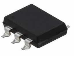
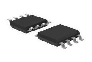
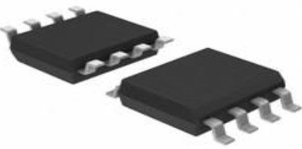
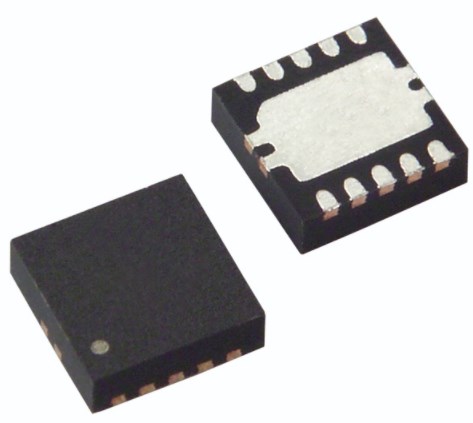
M24512-DF Package
The following diagrams show the M24512-DF Package.

View A

View B

View C

View D
M24512-DF Manufacturer
STMicroelectronics is a global independent semiconductor company and is a leader in developing and delivering semiconductor solutions across the spectrum of microelectronics applications. An unrivaled combination of silicon and system expertise, manufacturing strength, Intellectual Property (IP) portfolio and strategic partners positions the Company at the forefront of System-on-Chip (SoC) technology and its products play a key role in enabling today's convergence trends.
Datasheet PDF
- Datasheets :
- PCN Other :
How many pins of M24512-DFDW6TP?
8 Pins.
What’s the operating temperature of M24512-DFDW6TP?
-40°C~85°C TA.
What is the essential property of the M24512-DF?
The M24512-DF is a 512-Kbit I²C-compatible EEPROM (Electrically Erasable PROgrammable Memory) organized as 64 K × 8 bits. The M24512-DF can operate with a supply voltage from 1.7 V to 5.5 V.
 CS124 SSR RELAY SPST-NO 3.5A 0-40V: Datasheet, Features and Equivalents
11 January 2022321
 LM301A Operational Amplifier: Pinout, Features and Datasheet
08 November 20211764
 LM5002MAX/NOPB: Pinout, High-Voltage, CAD Model
21 February 2022954
 TPS74801DRCR Low-Dropout Linear Regulator: Pinout, Datasheet
16 August 20241210
 W77L516A 8-BIT Microcontroller: Technical Specifications and Applications
29 February 2024135
 1N4001 vs. 1N4148: Which one is better?
23 February 20227272
 LM741CN vs UA741CN : Which one is better?
26 February 20229895
 ADALM2000 Analog Device: Advanced Active Learning Module USB
11 January 20222383
 Selection and Optimization of Peripheral Components for DC-DC Boost Regulator
15 April 20222100
 Understanding of Carbon Film Resistors
17 October 202524392
 Working Principle and Characteristics of Zener diodes
20 October 202524972
 Introduction to Optical Amplifier
27 March 20259896
 Trimmer Resistors: From Principles to Selection and Applications
11 August 20252906
 Switching Power Supply Debugging: 10 Most Common Problems
26 December 202522413
 Introduction to PIC Microcontroller: Architecture, Features, and Applications
08 April 202512887
 Degson Authorized Distributor | UTMEL Electronics
21 November 20234048
STMicroelectronics
In Stock: 1990
Minimum: 1 Multiples: 1
Qty
Unit Price
Ext Price
1
$1.343573
$1.34
10
$1.267522
$12.68
100
$1.195775
$119.58
500
$1.128090
$564.04
1000
$1.064236
$1,064.24
Not the price you want? Send RFQ Now and we'll contact you ASAP.
Inquire for More Quantity
![M24C16-MN6]() M24C16-MN6
M24C16-MN6STMicroelectronics
![M48Z12-150PC1]() M48Z12-150PC1
M48Z12-150PC1STMicroelectronics
![M24512-RMN6TP]() M24512-RMN6TP
M24512-RMN6TPSTMicroelectronics
![M24C64-WMN6TP]() M24C64-WMN6TP
M24C64-WMN6TPSTMicroelectronics
![M93C46-WMN6TP]() M93C46-WMN6TP
M93C46-WMN6TPSTMicroelectronics
![M95512-WMN6TP]() M95512-WMN6TP
M95512-WMN6TPSTMicroelectronics
![M24C04-WMN6TP]() M24C04-WMN6TP
M24C04-WMN6TPSTMicroelectronics
![M24512-WMN6TP]() M24512-WMN6TP
M24512-WMN6TPSTMicroelectronics
![M24C02-WMN6TP]() M24C02-WMN6TP
M24C02-WMN6TPSTMicroelectronics
![M24C32-WMN6TP]() M24C32-WMN6TP
M24C32-WMN6TPSTMicroelectronics

