Trimmer Resistors: From Principles to Selection and Applications
Table of Contents
2.2 Trimmer Resistor vs. Fixed Resistor vs. Variable Resistor
5.3 History and Development Trends of Trimmer Resistors (Optional)
1.0 Introduction
In the intricate world of electronic circuits, achieving precise resistance values is paramount for optimal performance. When standard fixed resistors fall short of meeting minute adjustment needs, the trimmer resistor emerges as an indispensable component. Have you ever found yourself grappling with the challenge of fine-tuning a circuit to perfection? Perhaps you’ve encountered situations where a slight deviation in resistance could lead to significant performance issues. This is precisely where trimmer resistors shine, offering the ability to calibrate and fine-tune circuits with exceptional accuracy.
This comprehensive guide will embark on a journey to demystify the trimmer resistor, covering everything from its fundamental definition and distinctions from other resistor types to detailed selection criteria, practical applications, and advanced insights. We aim to provide you with a one-stop solution, empowering you to confidently select, utilize, and troubleshoot these crucial components in your electronic projects. According to recent market analysis, the demand for high-precision electronic components, including trimmer resistors, is projected to grow by 7% annually over the next five years, driven by advancements in IoT and automotive electronics. This underscores the increasing importance of understanding and effectively utilizing these versatile devices. By the end of this article, you will possess a thorough understanding of trimmer resistors, enabling you to make informed decisions and achieve unparalleled precision in your designs.
2.0 Trimmer Resistor Fundamentals
2.1 What is a Trimmer Resistor?
A trimmer resistor, often referred to as a trimpot or trimmer potentiometer, is a type of variable resistor used for making fine adjustments to the resistance in a circuit. Unlike potentiometers that are designed for frequent user interaction (like a volume knob), trimmer resistors are typically used for initial calibration or infrequent adjustments, a concept often described as “set and forget.” Once adjusted, they are expected to maintain their set resistance value over a long period.
The core function of a trimmer resistor is to provide a way to precisely tune a circuit’s parameters after it has been assembled. This is crucial because the actual values of other components in the circuit can have tolerances, meaning they might not be exactly their nominal value. A trimmer resistor allows an engineer or technician to compensate for these variations and tune the circuit to its optimal performance.
Structurally, a trimmer resistor consists of three main parts: a resistive element, a wiper (or sliding arm), and an adjustment screw. The resistive element can be made from various materials, such as carbon composition, cermet (a composite of ceramic and metal), or wirewound. The wiper moves along the resistive element as the adjustment screw is turned, changing the resistance between the wiper terminal and the two end terminals of the resistive element.
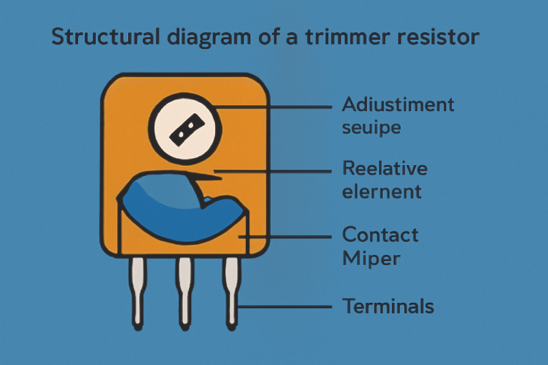
Structural diagram of a trimmer resistor
2.2 Trimmer Resistor vs. Fixed Resistor vs. Variable Resistor
Understanding the distinctions between trimmer resistors, fixed resistors, and other variable resistors like potentiometers is key to selecting the right component for your application.
Trimmer Resistor vs. Fixed Resistor
The most fundamental difference lies in their adjustability. A fixed resistor has a single, unchanging resistance value, defined at the time of manufacture. Its purpose is to introduce a specific, constant amount of resistance into a circuit. In contrast, a trimmer resistor offers an adjustable resistance within a specified range. This adjustability is its primary advantage, allowing for the fine-tuning of circuits. While you could theoretically use a trimmer resistor as a fixed resistor by setting it to a specific value, it’s not a cost-effective or stable solution for applications where a fixed resistance is required. For more information on fixed resistors, you can refer to this detailed guide on resistor types from Wikipedia.
Pro Tip: Use fixed resistors for established circuit designs where the resistance value is known and constant. Opt for trimmer resistors during the prototyping and calibration phases, or in circuits where periodic adjustments may be necessary.
Trimmer Resistor vs. Potentiometer
While both are types of variable resistors, their intended use cases are quite different. A potentiometer is designed for frequent, manual adjustments by the end-user. Think of the volume control on a stereo or a dimmer switch for a light. They are generally larger, more robust, and have a shaft or knob for easy manipulation. A trimmer resistor, on the other hand, is designed for infrequent adjustments, typically performed with a small screwdriver or a specialized tool. They are smaller, more delicate, and are usually mounted directly on the circuit board. This distinction is crucial for ensuring the longevity and reliability of your design. For a deeper dive into potentiometers, check out this excellent resource on potentiometers and their applications.
Here’s a comparison table to summarize the key differences:
| Feature | Trimmer Resistor | Fixed Resistor | Potentiometer |
|---|---|---|---|
| Adjustability | Yes, for fine-tuning | No, fixed value | Yes, for frequent user control |
| Intended Use | Calibration, infrequent adjustment | Providing a constant resistance | Frequent manual adjustment |
| Size | Small, compact | Varies, but generally small | Larger, with a knob or shaft |
| Adjustment Method | Screwdriver or special tool | Not applicable | Manual rotation of a knob/shaft |
| Durability | Lower mechanical lifespan | High | High mechanical lifespan |
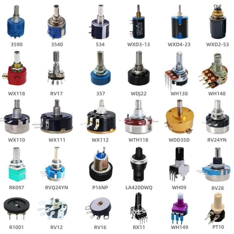
A collection of different types of trimmer resistors, showcasing various sizes and mounting styles. Image source: Wikipedia
3.0 Trimmer Resistor Selection Guide
Choosing the right trimmer resistor for your application is crucial for achieving desired circuit performance and reliability. This section will guide you through the essential factors to consider during the selection process.
3.1 Key Technical Specifications
When selecting a trimmer resistor, several technical specifications must be carefully evaluated to ensure compatibility and optimal performance within your circuit. Ignoring these can lead to instability, inaccuracy, or even component failure.
Resistance Range: This specifies the minimum and maximum resistance values the trimmer can provide. It is paramount to select a trimmer whose range encompasses the required adjustment span for your circuit. For instance, if you need to adjust a voltage divider from 1kΩ to 5kΩ, a trimmer with a 10kΩ range would be suitable, allowing for precise tuning within that span.
Tolerance: Expressed as a percentage (e.g., ±10%, ±20%), tolerance indicates the permissible deviation of the trimmer resistor’s nominal resistance value from its actual value. While a tighter tolerance generally implies higher precision, it often comes with a higher cost. For critical applications, a lower tolerance (e.g., ±5% or even ±1%) might be necessary to achieve the desired accuracy. However, for less sensitive circuits, a wider tolerance can be acceptable, offering a more budget-friendly solution.
Power Rating: Measured in Watts (W), the power rating defines the maximum power the trimmer resistor can safely dissipate without damage. It’s essential to ensure that the power dissipated by the trimmer in your circuit does not exceed its rated power. Over-dissipation can lead to overheating, resistance drift, and ultimately, component failure. Always calculate the maximum power the trimmer will experience under worst-case conditions and select a component with a sufficient power rating, ideally with a safety margin.
Temperature Coefficient of Resistance (TCR): TCR indicates how much the resistance value changes with temperature fluctuations, typically expressed in parts per million per degree Celsius (ppm/°C). A lower TCR signifies greater stability across varying temperatures, which is critical for applications operating in environments with significant temperature swings or requiring high precision over a wide temperature range. For example, a TCR of ±100 ppm/°C means that for every 1°C change in temperature, the resistance will change by 0.01% of its nominal value. In sensitive measurement equipment, a low TCR is highly desirable to maintain accuracy.
Number of Turns (Single-Turn vs. Multi-Turn): This specification refers to how many full rotations of the adjustment screw are required to traverse the entire resistance range. Single-turn trimmer resistors offer quick and easy adjustment but provide lower resolution, making them suitable for applications where rough adjustments are sufficient. In contrast, multi-turn trimmer resistors (e.g., 10-turn, 25-turn) provide significantly higher resolution and precision, allowing for very fine adjustments. This makes them ideal for applications requiring extremely accurate calibration, such as in precision instrumentation or audio equipment. The choice between single-turn and multi-turn depends directly on the level of adjustment granularity your circuit demands.
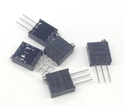
A multi-turn through-hole trimmer resistor, showing the adjustment screw. Image source: Amazon.com
3.2 SMD Trimmer Resistor Specifications and Selection
Surface Mount Device (SMD) trimmer resistors are increasingly prevalent in modern compact electronic designs due to their small footprint and suitability for automated assembly. When selecting SMD trimmers, in addition to the general technical specifications, consider these specific factors:
Package Size: SMD trimmers come in various miniature package sizes (e.g., 3mm, 4mm, 6mm square). The physical dimensions are critical for fitting the component onto crowded PCBs. Always refer to the manufacturer’s datasheet for exact dimensions and recommended footprint layouts.
Adjustment Orientation: SMD trimmers can have top, side, or front adjustment orientations. This choice depends on the accessibility requirements once the component is mounted on the PCB and enclosed within a product. For instance, if the trimmer needs to be adjusted after final assembly, a side or front adjustment might be more practical.
Element Type: While through-hole trimmers often use carbon film, SMD trimmers frequently utilize cermet resistive elements. Cermet trimmers offer superior stability, lower noise, and better temperature characteristics compared to carbon film, making them suitable for more demanding applications. For example, a cermet SMD trimmer might be preferred in a portable medical device where stability over temperature is paramount.
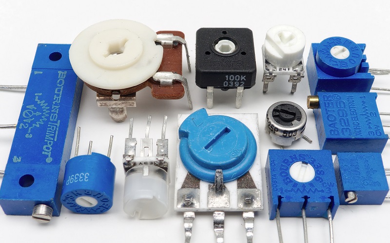
Various SMD trimmer resistors.
3.3 Industrial-Grade Trimmer Resistor Considerations
For applications in harsh environments or those requiring exceptional longevity and reliability, industrial-grade trimmer resistors are essential. These components are designed to withstand extreme conditions and maintain performance over extended periods. Key considerations include:
Environmental Robustness: Industrial trimmers are built to resist factors like high humidity, vibration, shock, and extreme temperatures. Look for specifications related to operating temperature range, humidity resistance, and vibration/shock ratings.
Lifespan and Reliability: These trimmers typically boast higher rotational life cycles and better long-term stability. This is crucial for equipment that needs to operate continuously for years without maintenance, such as in industrial control systems or telecommunications infrastructure.
Certifications: For automotive or other highly regulated industries, look for specific certifications like AEC-Q200 [1]. AEC-Q200 is a standard for passive electronic components used in automotive applications, ensuring they meet stringent reliability and quality requirements. This certification signifies that the component has undergone rigorous testing for stress, temperature, and electrical performance, making it suitable for demanding automotive environments.
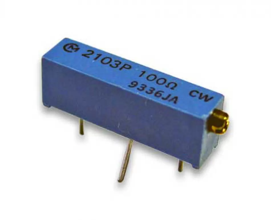
An industrial-grade multi-turn trimmer resistor, emphasizing its robust construction. Image source: RS Components
3.4 Comparison of Different Trimmer Resistor Types
Trimmer resistors are broadly categorized by the material used for their resistive element, primarily carbon film and cermet (ceramic-metal composite). Each type has distinct characteristics that make it suitable for different applications.
Carbon Film Trimmer Resistors
Carbon film trimmers are generally the most cost-effective option. They are made by depositing a thin film of carbon onto a ceramic substrate. While inexpensive, they typically offer lower precision, higher noise, and less stability over temperature and time compared to cermet types. Their tolerance is usually wider (e.g., ±20%), and their TCR is higher. They are best suited for non-critical applications where cost is a primary concern and high precision is not required, such as in consumer electronics or hobbyist projects.
Cermet Trimmer Resistors
Cermet trimmers are constructed by firing a mixture of conductive metal and insulating ceramic materials onto a substrate. This manufacturing process results in a highly stable and precise resistive element. Cermet trimmers offer superior performance characteristics, including:
Higher Precision: Tighter tolerances (e.g., ±10% or ±5%) are common.
Better Stability: Excellent long-term stability and lower resistance drift over time.
Lower TCR: Significantly lower temperature coefficients, making them ideal for temperature-sensitive applications.
Lower Noise: Reduced electrical noise compared to carbon film.
Higher Power Handling: Generally capable of dissipating more power.
Due to their enhanced performance, cermet trimmers are preferred in applications requiring high accuracy, stability, and reliability, such as medical equipment, industrial controls, and precision test and measurement instruments. While they are more expensive than carbon film trimmers, their superior performance often justifies the cost in demanding scenarios.
Here’s a comparative overview:
| Feature | Carbon Film Trimmer | Cermet Trimmer |
|---|---|---|
| Cost | Lower | Higher |
| Precision | Lower | Higher |
| Stability | Lower | Higher |
| TCR | Higher | Lower |
| Noise | Higher | Lower |
| Power Handling | Lower | Higher |
| Typical Applications | Consumer electronics, hobby projects | Medical, industrial, precision instrumentation |
4.0 Trimmer Resistor Applications and Practice
Trimmer resistors are versatile components that find their utility across a broad spectrum of electronic applications. Their ability to provide precise, infrequent adjustments makes them indispensable in circuits where fine-tuning is critical for optimal performance. Let’s explore some of their core applications and practical considerations.
4.1 Core Applications of Trimmer Resistors in Circuits
Trimmer resistors are primarily used for calibration and fine-tuning various circuit parameters. Their presence allows engineers to compensate for component tolerances, environmental variations, and aging effects, ensuring the circuit operates as intended.
Voltage/Current Calibration: One of the most common applications is to precisely set voltage or current levels in a circuit. For example, in power supplies, a trimmer resistor can be used to fine-tune the output voltage to an exact value, compensating for slight variations in other components. Similarly, in current sources, they can adjust the output current to a specific level.
Signal Level Trimming and Bias Setting: In analog circuits, trimmer resistors are frequently employed to adjust signal amplitudes or set bias points for active components like transistors and operational amplifiers. This ensures that these components operate in their optimal linear regions, minimizing distortion and maximizing performance. For instance, in an audio amplifier, a trimmer might be used to set the quiescent current of output transistors, which directly impacts sound quality.
Fine Adjustment of Sensor Output Signals: Sensors often produce analog output signals that need to be precisely scaled or offset to match the input requirements of subsequent processing stages (e.g., analog-to-digital converters). Trimmer resistors provide the means to perform these fine adjustments, ensuring accurate data acquisition. Imagine a temperature sensor whose output needs to be calibrated to a specific voltage range for a microcontroller; a trimmer can achieve this precision.
Oscillator Frequency Trimming: In oscillator circuits, the frequency of oscillation can be sensitive to component tolerances. Trimmer resistors (or trimmable capacitors, in some cases) are used to precisely set the oscillation frequency to the desired value. This is vital in applications like communication systems, timing circuits, and clock generators where accurate frequency is paramount.
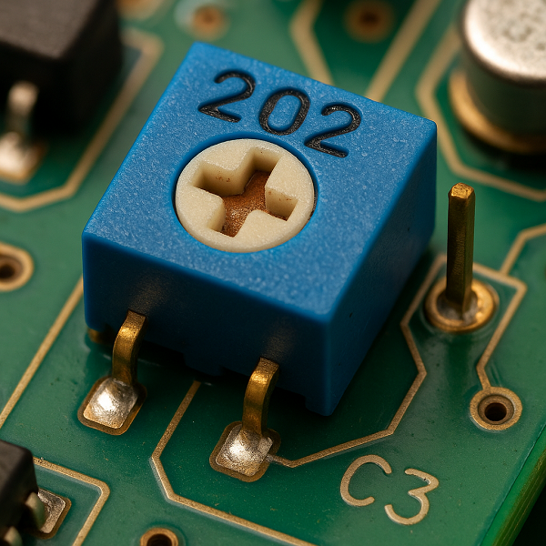
A close-up of a trimmer resistor on a circuit board.
4.2 Application Case Studies in Specific Fields
To further illustrate their utility, let’s look at how trimmer resistors are applied in specific industries and devices.
In Audio Equipment: Trimmer resistors are fundamental in high-fidelity audio circuits. They are used for setting amplifier bias points, fine-tuning the cutoff frequencies of active filters (like those in crossovers), and balancing stereo channels. For example, in a guitar pedal, a trimmer might be used to set the exact gain stage or the blend of wet/dry signals, allowing for subtle sonic variations that fixed resistors cannot provide. This level of control is what gives audio engineers the ability to sculpt precise sound profiles.
In Power Supply Modules: Precision power supplies often rely on trimmer resistors to achieve highly accurate and stable output voltages. Even small deviations in voltage can be detrimental to sensitive electronic components. Trimmers allow manufacturers to calibrate each power supply unit to its exact specified output, compensating for manufacturing variances in other components. This ensures that the power supply delivers consistent and reliable power, which is critical for the longevity and performance of the devices it powers.
This video provides a basic overview of how to use a trimmer potentiometer as a variable resistor or voltage divider on a breadboard, offering a practical demonstration for beginners.
4.3 Operation and Troubleshooting Guide
Proper handling and adjustment of trimmer resistors are essential to avoid damage and ensure accurate calibration. Knowing how to troubleshoot common issues can also save significant time and effort.
Trimmer Resistor Adjustment Method Guide
Adjusting a trimmer resistor requires patience and the right tools. Here’s a step-by-step guide:
Gather Tools: You will typically need a small, non-conductive screwdriver (often ceramic or plastic) specifically designed for electronic adjustments. Using a metal screwdriver can introduce capacitance or inductance, affecting the circuit, or even cause a short circuit.
Safety First: Before making any adjustments, it’s advisable to power down the circuit if possible. If the circuit must remain powered, ensure you understand the live points and take extreme caution to avoid short circuits or electric shock. Always use insulated tools.
Connect Measurement Device: Use a multimeter to measure the resistance or voltage at the point you are adjusting. For resistance adjustment, connect the multimeter across the relevant terminals of the trimmer or the part of the circuit whose resistance you are setting. For voltage adjustment, connect it to the point where the voltage needs to be calibrated.
Gentle Adjustment: Insert the screwdriver into the adjustment slot of the trimmer. Turn it slowly and gently. Multi-turn trimmers will require many rotations to cover their full range, so be patient. Observe the multimeter reading as you adjust. Avoid forcing the screw, as this can damage the internal mechanism.
Iterative Refinement: For precise adjustments, it’s often best to approach the target value slowly. If you overshoot, adjust back in the opposite direction. For multi-turn trimmers, you might turn a few full rotations to get close, then make smaller, fractional turns for fine-tuning.
Important Note: Some trimmers have mechanical stops at their minimum and maximum resistance values. Do not force the adjustment screw past these stops, as it can cause irreversible damage to the trimmer.
Common Fault Diagnosis and Repair
While generally reliable, trimmer resistors can occasionally fail or exhibit problematic behavior. Here are some common issues and troubleshooting tips:
Resistance Drift: The set resistance value changes over time without adjustment. This can be caused by temperature fluctuations, aging, or excessive power dissipation. If drift is significant, the trimmer may need replacement.
Intermittent Contact/Open Circuit: The resistance value becomes erratic or goes to infinity (open circuit) when the trimmer is adjusted or even when the circuit is stable. This often indicates a poor connection between the wiper and the resistive element, possibly due to wear, contamination, or physical damage. This is a common failure mode for older or frequently adjusted trimmers.
Physical Damage: Visible signs of damage, such as a broken housing, bent pins, or a stripped adjustment screw. This usually occurs due to improper handling or excessive force during adjustment.
Troubleshooting Methods:
Visual Inspection: Check for any obvious physical damage, discoloration (indicating overheating), or loose connections.
Multimeter Measurement: With the circuit powered off (and ideally the trimmer desoldered for accurate measurement), use a multimeter to measure the resistance across the end terminals and between the wiper and each end terminal. Compare these readings with the expected values. An open circuit or highly unstable readings indicate a faulty trimmer.
Repair Suggestions:
In most cases, repairing a faulty trimmer resistor is not recommended or practical. Due to their sealed nature and delicate internal mechanisms, attempting to repair them often leads to further damage or unreliable performance. The most effective and reliable solution is to replace the faulty trimmer resistor with a new one of the correct specifications. This ensures the circuit returns to its intended performance and reliability levels.
This video from The Learning Circuit provides a comprehensive overview of various resistor types, including a brief mention of variable resistors like trimmers, offering broader context on their role in electronics.
5.0 Advanced Knowledge and Market Analysis
Beyond the fundamental principles and selection criteria, a deeper understanding of trimmer resistors involves exploring advanced technical aspects and their position within the broader electronics market. This section delves into these more nuanced topics, providing insights for those seeking to optimize their designs and make informed purchasing decisions.
5.1 Advanced Technical Discussions
As electronic circuits become more sophisticated, the demands placed on components like trimmer resistors also increase. Two areas of advanced discussion are temperature compensation and high-precision measurement techniques.
Temperature Compensation in Trimmer Resistors
While we touched upon the Temperature Coefficient of Resistance (TCR) earlier, it’s worth noting that in highly sensitive applications, even a low TCR might not be sufficient. Temperature-compensated trimmer resistors are designed to minimize resistance changes due to temperature fluctuations even further. This is often achieved by carefully selecting resistive materials with opposing TCR characteristics or by integrating additional temperature-sensitive components into the trimmer’s design. The goal is to create a composite system where the overall resistance remains remarkably stable across a wide operating temperature range. This is particularly critical in precision measurement equipment, medical devices, and aerospace applications where even minute resistance variations can lead to significant errors. For instance, in a high-accuracy data acquisition system, a temperature-compensated trimmer ensures that the calibration remains consistent regardless of ambient temperature changes, thereby maintaining the integrity of the collected data.
High-Precision Trimmer Resistor Measurement Techniques
Achieving and verifying the precise resistance setting of a trimmer resistor, especially multi-turn and high-precision types, requires specialized measurement techniques beyond a standard multimeter. These techniques often involve:
Bridge Circuits: Wheatstone bridge or Kelvin bridge configurations are commonly used for highly accurate resistance measurements. By balancing the bridge, extremely small resistance changes can be detected, allowing for precise adjustment of the trimmer to a target value. This method is often employed in laboratory settings or during the manufacturing calibration of sensitive instruments.
Automated Test Equipment (ATE): For high-volume production or complex circuit boards, ATE systems are utilized. These systems can rapidly and accurately adjust multiple trimmer resistors simultaneously, often using robotic arms and sophisticated algorithms to achieve optimal circuit performance. ATE ensures consistency and efficiency in the calibration process, reducing human error and production time.
Environmental Chambers: To assess the long-term stability and TCR of trimmer resistors, they are often subjected to controlled temperature cycles within environmental chambers. Resistance measurements are taken at various temperature points to characterize their performance under different thermal conditions. This rigorous testing helps manufacturers and engineers select trimmers that will perform reliably in their intended operating environments.
5.2 Market and Brand Overview
The market for trimmer resistors is diverse, with several key manufacturers offering a wide range of products catering to different application needs. Understanding the landscape of leading brands can help in making informed decisions.
Leading Brands in Precision Trimmer Resistors
Several companies have established themselves as leaders in the production of high-quality trimmer resistors, known for their reliability, precision, and broad product portfolios. Some of the most prominent include:
Bourns: A global leader in electronic components, Bourns is particularly renowned for its Trimpot® trimming potentiometers. They offer an extensive selection of single-turn and multi-turn trimmers in various package styles (through-hole and SMD) and resistive materials (cermet, wirewound). Bourns trimmers are widely used across industrial, automotive, and consumer electronics sectors due to their robust design and consistent performance. Their AEC-Q200 compliant series is a testament to their commitment to quality in demanding applications.
Vishay: Vishay Intertechnology is another major player, offering a comprehensive range of passive electronic components, including a strong lineup of trimmer potentiometers. Vishay trimmers are known for their high reliability and are often found in precision instrumentation and military-grade applications. They provide various configurations, including cermet and wirewound elements, catering to diverse engineering requirements.
Murata: While perhaps more known for ceramic capacitors and inductors, Murata also produces high-quality trimmer potentiometers, particularly in compact SMD packages. Their focus on miniaturization and high-frequency performance makes their trimmers suitable for portable devices and communication equipment. Murata’s commitment to innovation ensures their trimmers meet the evolving demands of modern electronics.
TT Electronics: This global manufacturer offers a range of resistive products, including precision trimmers. TT Electronics trimmers are often chosen for their robust construction and suitability for harsh environments, making them a preferred choice in industrial and aerospace applications. They emphasize reliability and performance under challenging conditions.
When selecting a brand, consider not only the product specifications but also the manufacturer’s reputation for quality, technical support, and availability. For example, if you are designing for an automotive application, prioritizing brands with a strong portfolio of AEC-Q200 compliant parts like Bourns or Vishay would be a wise decision.
5.3 History and Development Trends of Trimmer Resistors (Optional)
The evolution of trimmer resistors mirrors the broader advancements in electronics, driven by the continuous demand for smaller, more precise, and more reliable components. From their early forms to the sophisticated SMD devices of today, trimmers have undergone significant transformations.
Historically, early variable resistors were often larger, more cumbersome devices, primarily used for manual adjustments. As circuits became more compact and the need for internal calibration grew, the concept of a‘set-and-forget’ adjustable resistor emerged. This led to the development of the first dedicated trimmer resistors, which were typically through-hole components with carbon composition or wirewound elements.
The advent of surface-mount technology (SMT) revolutionized component manufacturing, leading to the miniaturization of trimmer resistors. SMD trimmers, with their smaller footprints and suitability for automated assembly, became essential for compact electronic devices. Concurrently, advancements in materials science led to the widespread adoption of cermet resistive elements, offering superior stability, precision, and temperature characteristics compared to their carbon film predecessors.
Looking ahead, the trend for trimmer resistors is likely to continue towards even higher precision, smaller form factors, and enhanced long-term stability. The increasing complexity of electronic systems, particularly in areas like IoT, artificial intelligence, and advanced automotive electronics, will drive the demand for trimmers that can offer ultra-fine adjustments and maintain their performance under increasingly challenging environmental conditions. Furthermore, there might be a growing emphasis on digital trimming solutions, where resistance values are adjusted electronically, offering greater control and integration with digital systems, though mechanical trimmers will likely remain relevant for many applications due to their simplicity and cost-effectiveness.
6.0 Conclusion and FAQ
6.1 Conclusion
In the intricate landscape of electronic design, the trimmer resistor stands as an indispensable tool for achieving precision and optimal performance. We have journeyed through its fundamental principles, distinguishing it from fixed and variable resistors, and explored the critical factors that govern its selection. From understanding key technical specifications like resistance range, tolerance, power rating, and TCR, to navigating the nuances of SMD and industrial-grade options, the path to choosing the right trimmer is now clearer.
We’ve also delved into the diverse applications of trimmer resistors, from calibrating voltages and currents to fine-tuning sensor outputs and oscillator frequencies, showcasing their pervasive utility across various industries. The practical guidance on adjustment methods and troubleshooting common issues equips you with the hands-on knowledge necessary for successful implementation. Finally, our exploration of advanced topics and market trends provides a holistic view of these vital components.
Ultimately, the selection of a trimmer resistor boils down to three critical considerations: the type (single-turn vs. multi-turn, carbon film vs. cermet), the specifications required by your circuit (resistance, tolerance, power, TCR), and the application scenario (consumer, industrial, precision). By carefully evaluating these aspects, you can confidently integrate the ideal trimmer resistor into your designs, unlocking unparalleled precision and reliability. We encourage you to apply the insights gained from this guide to your next electronic project, ensuring your circuits perform with the accuracy they demand.
6.2 Frequently Asked Questions (FAQ)
Q1: Can a trimmer resistor be used as a regular fixed resistor?
A1: Theoretically, yes, you can set a trimmer resistor to a specific value and use it as a fixed resistor. However, it is generally not recommended for several reasons. Trimmer resistors are typically more expensive than fixed resistors of comparable values. More importantly, their stability over time and temperature is usually not as good as dedicated fixed resistors, which are designed for long-term, stable resistance. Therefore, for applications requiring a fixed resistance, it’s always better to use a standard fixed resistor.
Q2: How do I read the code on an SMD trimmer resistor?
A2: SMD trimmer resistors often use a 3-digit or 4-digit code, similar to other SMD resistors. The first two (or three) digits represent the significant figures of the resistance value, and the last digit represents the multiplier (the number of zeros to follow). For example, a code
‘103’ would mean 10 followed by 3 zeros, which is 10,000 ohms or 10kΩ. A code ‘220’ would be 22 followed by 0 zeros, meaning 22 ohms. Some manufacturers might use different coding schemes, so it’s always best to consult the component’s datasheet if you are unsure.
Q3: What are the advantages of a “multi-turn” trimmer resistor over a “single-turn” one?
A3: The primary advantage of a multi-turn trimmer resistor is its significantly higher adjustment precision and resolution. A single-turn trimmer completes its entire resistance range in one full rotation of the adjustment screw, making fine adjustments challenging. In contrast, a multi-turn trimmer requires multiple rotations (e.g., 10, 20, or 25 turns) to cover its full resistance range. This allows for much finer control and more accurate setting of the desired resistance value, making them ideal for applications where extremely precise calibration is necessary, such as in sensitive analog circuits or test equipment.
Further Reading:
 What are the Differences Between Pull up and Pull down Resistors?UTMEL22 October 202534371
Pull up is to clamp an uncertain signal to a high level with a resistor, and the resistor also acts as a current limiter. In the same way, pull down means to clamp the uncertain signal to a low level through a resistor. To pull up is to input current to the device, and the pull-down is to output the current.
Read More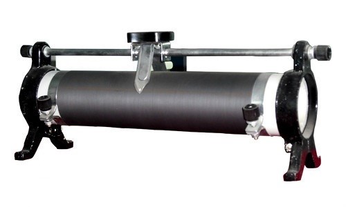 Rheostat Basics: Types, Principle and FunctionsUTMEL25 December 202515644
A rheostat is a device that can adjust the size of the resistance and can be connected to the circuit to adjust the size of the current. A general rheostat is composed of a wire with a larger resistance and a device that can change the contact point to adjust the effective length of the resistance wire. Rheostat can limit the current and protect the circuit, and change the voltage distribution in the circuit.
Read More Basic Introduction to Metal Film ResistorUTMEL28 August 202011359
Metal film resistors are a kind of film resistors. Metal film resistors are resistors in which special metals or alloys are used as resistor materials, and the resistor film layer is basically formed on ceramic or glass by vacuum evaporation or sputtering.
Read More Varistor: Definition, Function, Working and TestingUTMEL03 April 202580475
A varistor is a device with a non-linear volt-ampere characteristic. When the voltage applied to the varistor is lower than its threshold value, the current flowing through it is extremely small, which is equivalent to a resistor with infinite resistance, vice versa. The most common varistor is a metal oxide varistor (MOV).
Read More Photoresistor Basics: Types, Principles and ApplicationsUTMEL16 October 202541762
The article introduces the photoresistor’s main characteristics and principles including the working principle and structural principle. There are three types of photoresistor: ultraviolet photoresistors, infrared photoresistors, visible light photoresistors. Dimming circuit and light switch are the two applications of the photoresistor.
Read More
Subscribe to Utmel !
![AD8364ACPZ-REEL7]() AD8364ACPZ-REEL7
AD8364ACPZ-REEL7Analog Devices Inc.
![HMC576LC3BTR]() HMC576LC3BTR
HMC576LC3BTRAnalog Devices Inc.
![HMC717ALP3E]() HMC717ALP3E
HMC717ALP3EAnalog Devices Inc.
![MICRF221AYQS]() MICRF221AYQS
MICRF221AYQSMicrochip Technology
![HMC504LC4B]() HMC504LC4B
HMC504LC4BAnalog Devices Inc.
![MICRF219AAYQS]() MICRF219AAYQS
MICRF219AAYQSMicrochip Technology
![MICRF002YM]() MICRF002YM
MICRF002YMMicrochip Technology
![LT5581IDDB#TRMPBF]() LT5581IDDB#TRMPBF
LT5581IDDB#TRMPBFLinear Technology/Analog Devices
![SI4010-C2-GS]() SI4010-C2-GS
SI4010-C2-GSSilicon Labs
![ADL5330ACPZ-R2]() ADL5330ACPZ-R2
ADL5330ACPZ-R2Analog Devices Inc.


