
 Product
 Brand
Brand Articles
 Tools
Tools
AD795 Precision FET Op-Amp: OPA111 Replacement Notes and Design Trade-Offs

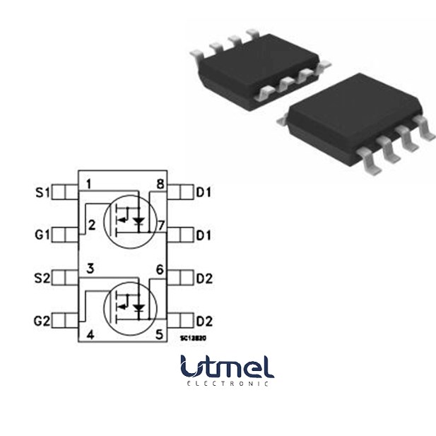
1 Channels 10mA per Channel 1pA 110 dB Instrumentational OP Amps 0.000003μA 8V~36V ±4V~18V AD795 8 Pins 8-SOIC (0.154, 3.90mm Width)


1 Channels 10mA per Channel 1pA 110 dB Instrumentational OP Amps 0.000003μA 8V~36V ±4V~18V AD795 8 Pins 8-SOIC (0.154, 3.90mm Width)
Evaluate the AD795 precision FET op-amp for high-impedance instrumentation. Review critical noise specs, OPA111/OPA121 replacement guidelines, and thermal trade-offs.
- Migrating from Burr-Brown OPA111 and OPA121
- Thermal Constraints: Managing the FET Input Bias Current
- Electrical Specifications: The Noise vs. Offset Trade-Off
- Core Applications in High-Impedance Instrumentation
- Assessing Modern Alternatives and Upgrades
- Manufacturing Warnings: ESD Sensitivity
- Datasheet Verification and BOM Release
- Frequently Asked Questions
- Specifications
- Parts with Similar Specs
- Datasheet PDF
The AD795 is a low power, low noise precision FET input operational amplifier designed for high input impedance instrumentation and precision signal conditioning. For design engineers and procurement specialists dealing with legacy precision circuits or specific high-impedance sensor interfaces, understanding the exact operational limits of this amplifier is critical to ensuring long-term system stability.
Primary function: High-accuracy amplification for high-impedance sources.
Key positioning: Engineered as a low-power replacement for legacy Burr-Brown precision amplifiers.
Design constraint: Strict thermal management is required due to FET input characteristics.
Migrating from Burr-Brown OPA111 and OPA121
One of the most prominent reasons the AD795 is selected during BOM reviews is its role as a low-power replacement for the aging Burr-Brown (now Texas Instruments) OPA111 and OPA121 operational amplifiers.
When transitioning legacy designs away from the OPA111/121, power consumption is typically the primary benefit. The AD795 limits supply current to a 1.5 mA maximum, significantly reducing the thermal load on the PCB compared to older, power-hungry precision op-amps. This reduction in power dissipation inherently improves the local thermal environment, which is a critical factor for any FET-input amplifier.
However, replacing legacy components is rarely a zero-effort task. While the AD795 is targeted as a direct functional upgrade, engineers must meticulously verify the surrounding passive components. The feedback loop stability, particularly in precision I-to-V converters, may need slight tuning due to the AD795's 1.6 MHz Gain Bandwidth Product (GBW). Drop-in replacements should always be validated through bench testing to ensure that the lower supply current does not alter the expected slew rate or transient response of the original circuit.
Thermal Constraints: Managing the FET Input Bias Current
The most significant engineering compromise when designing with the AD795 involves its behavior over temperature. At room temperature, the device boasts an exceptionally low input bias current of 2 pA maximum. This allows it to interface seamlessly with high-impedance sources without dragging down the signal.
However, because the AD795 utilizes a FET input stage, this bias current is highly temperature-sensitive. As a rule of physics for this architecture, the input bias current doubles for every 10°C increase in temperature.
If this amplifier is placed near a hot-running power regulator or enclosed in a poorly ventilated chassis, a 2 pA bias current at 25°C can quickly escalate to levels that completely degrade the precision of a sensitive analog front end. Furthermore, the component is rated for a relatively narrow operating temperature range of 0°C to 70°C.
Design Mitigation Strategies:* Thermal Isolation: Keep the amplifier physically isolated from heat-generating power components on the PCB layout. * Active Cooling: Ensure the ambient environment remains stable, utilizing active cooling if the enclosure is prone to heat buildup. * Leakage Compensation: In highly sensitive circuits, designers must actively compensate for leakage currents in the software domain or through hardware trimming as the system warms up.
Electrical Specifications: The Noise vs. Offset Trade-Off
Precision analog design is an exercise in balancing competing specifications. The AD795 excels in low-frequency noise performance but forces a compromise on absolute DC offset.
Voltage Noise Density: The amplifier delivers an impressive 11 nV/√Hz maximum at 10 kHz, alongside a low 3.3 μV p-p maximum (0.1 Hz to 10 Hz) noise floor. This makes it exceptionally capable of resolving tiny variations in low-frequency signals without burying the data in thermal noise.
Offset Voltage: The trade-off for this low noise and low bias current is a relatively high offset voltage of 500 μV maximum, coupled with a drift of 10 μV/°C maximum.
By modern standards, a 500 μV offset falls significantly behind contemporary auto-zero or chopper-stabilized precision op-amps. If your design requires ultra-low DC offset right out of the box, the AD795 will likely require software calibration routines upon system boot, or manual hardware trimming via a potentiometer during factory assembly.
Core Applications in High-Impedance Instrumentation
Because of its specific blend of low bias current and low noise, the AD795 is highly specialized for applications where the sensor itself cannot drive a heavy load.
Low Noise Photodiode Preamps: Photodiodes output extremely small currents. The 2 pA maximum bias current ensures that the amplifier does not consume the very signal it is supposed to measure.
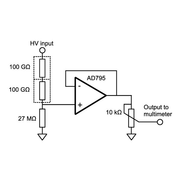
Precision I-to-V Converters (Transimpedance Amplifiers): Converting tiny currents to usable voltages requires minimal leakage and low voltage noise density to maintain dynamic range.
CT Scanners and Medical Imaging: These systems demand high stability and extremely low noise floors in the 0.1 Hz to 10 Hz band to resolve high-contrast diagnostic images.
Assessing Modern Alternatives and Upgrades
If you are maintaining an existing BOM, the AD795 remains a steadfast choice. However, for greenfield designs or situations where the 500 μV offset voltage is a dealbreaker, the market offers several modern alternatives that should be evaluated:
Texas Instruments OPA189 & Analog Devices ADA4522: Both are modern zero-drift/chopper-stabilized amplifiers. They will completely eliminate the 500 μV offset penalty (often offering sub-5 μV offsets). However, engineers must be cautious: chopper amplifiers introduce high-frequency switching noise that can couple into high-impedance sources like photodiodes.
Linear Technology (ADI) LTC2057: Another excellent zero-drift alternative, but similar caveats regarding switching noise apply.
Replacing a linear FET amplifier like the AD795 with a modern chopper requires careful re-evaluation of the circuit's EMI and high-frequency noise rejection.
Manufacturing Warnings: ESD Sensitivity
The FET input architecture makes the device highly vulnerable to electrostatic discharge (ESD). Minor ESD events during pick-and-place operations or manual prototyping can easily degrade the delicate gate structures, resulting in permanently elevated bias currents or complete failure. Strict ESD precautions—including grounded workstations, wrist straps, and controlled humidity environments—are mandatory during handling, PCB assembly, and testing.
Datasheet Verification and BOM Release
Before finalizing a BOM or sending a design to layout, procurement and engineering teams must verify mechanical and ordering specifics. Because exact package dimensions and tape-and-reel suffix codes dictate automated assembly compatibility, confirming these details in the latest manufacturer revision notes is strictly required. Ensure that the selected ordering code matches the required 0°C to 70°C commercial temperature grade, and verify that the EDA footprint aligns perfectly with the chosen package to avoid costly PCB respins.
Frequently Asked Questions
Why does my AD795 circuit lose DC accuracy as the system warms up?
Because the AD795 uses a FET input stage, its input bias current (rated at 2 pA maximum at room temperature) doubles for every 10°C increase in ambient temperature. If your board environment gets hot, this escalating leakage current will interact with your high-impedance source, creating a noticeable DC voltage error.
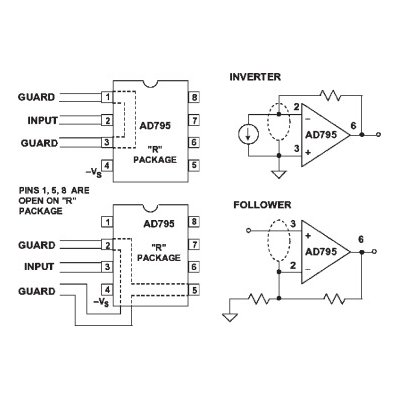
Can I drop the AD795 directly into a Burr-Brown OPA111 socket?
The AD795 is specifically designed as a low-power replacement for the OPA111 and OPA121. However, while the pinout and core functionality align, you must verify that the AD795's 1.6 MHz GBW and specific offset voltage parameters meet the exact timing and accuracy requirements of your legacy circuit.
Is it better to use the AD795 or upgrade to a modern zero-drift amplifier like the ADA4522?
It depends entirely on your sensor. If you strictly need ultra-low offset voltage (eliminating the AD795's 500 μV max offset), the ADA4522 is superior. However, zero-drift amplifiers use internal chopping circuitry that can inject high-frequency noise into the source. For extremely sensitive photodiode applications, the linear FET architecture of the AD795 often provides a cleaner signal path.
Watch Tutorial: AD795
Specifications
Parts with Similar Specs
- ImagePart NumberManufacturerPackage / CaseNumber of PinsSlew RateGain Bandwidth ProductInput Offset Voltage (Vos)Power Supply Rejection Ratio (PSRR)Common Mode Rejection RatioSupply VoltageView Compare
![AD795JRZ-REEL7]()
AD795JRZ-REEL7
8-SOIC (0.154, 3.90mm Width)
8
1V/μs
1.6 MHz
500 μV
110 dB
110 dB
15 V
![OP1177ARZ]()
8-SOIC (0.154, 3.90mm Width)
8
1V/μs
1.6 MHz
500 μV
110 dB
110 dB
15 V
![AD795JRZ]()
8-SOIC (0.154, 3.90mm Width)
8
1V/μs
1.6 MHz
100 μV
86 dB
110 dB
15 V
![AD795JR]()
8-SOIC (0.154, 3.90mm Width)
8
0.7V/μs
-
60 μV
130 dB
125 dB
5 V

Datasheet PDF
- Datasheets :
- ConflictMineralStatement :
 2N5484 Transistor: 2N5484 Datasheet, Pinout, Equivalent
21 February 20222719
.png) Unveiling the Renesas RH850/F1L Microcontroller: Automotive Application Powerhouse
Unveiling the Renesas RH850/F1L Microcontroller: Automotive Application Powerhouse29 February 20241154
 ATmega8A 8-bit microcontroller: ATmega8A, Pinout, Datasheet
23 December 202112607
- AD558: A Versatile Digital to Analog Converter for Precise Voltage Output
06 March 2024404
 ICL7107 ADC Display Driver: Price, Application and Datasheet
25 August 20213784
 STS4DNF60L:datasheet, pinout and specifications
11 March 2022438
 STPS20H100CT Microcontroller: 72MHz, 48-LQFP, Pinout and Datasheet
12 February 20222933
 LTC3780 Buck-Boost Controller: Alternative, Price and Datasheet
21 July 20214866
 Photonic Integrated Circuits: Overcoming Challenges in Silicon Photonics
26 August 20242908
 MEMS Basics: System Features and Classifications
11 June 20217081
 Amkor Technology to Invest $2 Billion in Semiconductor Testing Plant in Peoria, Creating 2,000 Jobs
11 December 20234438
 What is a Ceramic Filter?
10 April 20214608
 State-of-Charge Estimation Techniques for Lithium-Ion Batteries
26 January 20242527
 PMIC - Gate Drivers: A Purpose-Built Integrated Circuit
22 February 20233252
 AC/DC, DC/DC Converter Fundamental Guide
31 March 202613599
 Best Practices for Panel Meter Maintenance
11 July 20251187
Analog Devices Inc.
In Stock: 20
United States
China
Canada
Japan
Russia
Germany
United Kingdom
Singapore
Italy
Hong Kong(China)
Taiwan(China)
France
Korea
Mexico
Netherlands
Malaysia
Austria
Spain
Switzerland
Poland
Thailand
Vietnam
India
United Arab Emirates
Afghanistan
Åland Islands
Albania
Algeria
American Samoa
Andorra
Angola
Anguilla
Antigua & Barbuda
Argentina
Armenia
Aruba
Australia
Azerbaijan
Bahamas
Bahrain
Bangladesh
Barbados
Belarus
Belgium
Belize
Benin
Bermuda
Bhutan
Bolivia
Bonaire, Sint Eustatius and Saba
Bosnia & Herzegovina
Botswana
Brazil
British Indian Ocean Territory
British Virgin Islands
Brunei
Bulgaria
Burkina Faso
Burundi
Cabo Verde
Cambodia
Cameroon
Cayman Islands
Central African Republic
Chad
Chile
Christmas Island
Cocos (Keeling) Islands
Colombia
Comoros
Congo
Congo (DRC)
Cook Islands
Costa Rica
Côte d’Ivoire
Croatia
Cuba
Curaçao
Cyprus
Czechia
Denmark
Djibouti
Dominica
Dominican Republic
Ecuador
Egypt
El Salvador
Equatorial Guinea
Eritrea
Estonia
Eswatini
Ethiopia
Falkland Islands
Faroe Islands
Fiji
Finland
French Guiana
French Polynesia
Gabon
Gambia
Georgia
Ghana
Gibraltar
Greece
Greenland
Grenada
Guadeloupe
Guam
Guatemala
Guernsey
Guinea
Guinea-Bissau
Guyana
Haiti
Honduras
Hungary
Iceland
Indonesia
Iran
Iraq
Ireland
Isle of Man
Israel
Jamaica
Jersey
Jordan
Kazakhstan
Kenya
Kiribati
Kosovo
Kuwait
Kyrgyzstan
Laos
Latvia
Lebanon
Lesotho
Liberia
Libya
Liechtenstein
Lithuania
Luxembourg
Macao(China)
Madagascar
Malawi
Maldives
Mali
Malta
Marshall Islands
Martinique
Mauritania
Mauritius
Mayotte
Micronesia
Moldova
Monaco
Mongolia
Montenegro
Montserrat
Morocco
Mozambique
Myanmar
Namibia
Nauru
Nepal
New Caledonia
New Zealand
Nicaragua
Niger
Nigeria
Niue
Norfolk Island
North Korea
North Macedonia
Northern Mariana Islands
Norway
Oman
Pakistan
Palau
Palestinian Authority
Panama
Papua New Guinea
Paraguay
Peru
Philippines
Pitcairn Islands
Portugal
Puerto Rico
Qatar
Réunion
Romania
Rwanda
Samoa
San Marino
São Tomé & Príncipe
Saudi Arabia
Senegal
Serbia
Seychelles
Sierra Leone
Sint Maarten
Slovakia
Slovenia
Solomon Islands
Somalia
South Africa
South Sudan
Sri Lanka
St Helena, Ascension, Tristan da Cunha
St. Barthélemy
St. Kitts & Nevis
St. Lucia
St. Martin
St. Pierre & Miquelon
St. Vincent & Grenadines
Sudan
Suriname
Svalbard & Jan Mayen
Sweden
Syria
Tajikistan
Tanzania
Timor-Leste
Togo
Tokelau
Tonga
Trinidad & Tobago
Tunisia
Turkey
Turkmenistan
Turks & Caicos Islands
Tuvalu
U.S. Outlying Islands
U.S. Virgin Islands
Uganda
Ukraine
Uruguay
Uzbekistan
Vanuatu
Vatican City
Venezuela
Wallis & Futuna
Yemen
Zambia
Zimbabwe
![AD826AR-REEL7]() AD826AR-REEL7
AD826AR-REEL7Analog Devices Inc.
![AD8062ARM]() AD8062ARM
AD8062ARMAnalog Devices Inc.
![AD8532ARU-REEL]() AD8532ARU-REEL
AD8532ARU-REELAnalog Devices Inc.
![OP113ES]() OP113ES
OP113ESAnalog Devices Inc.
![SSM2142P]() SSM2142P
SSM2142PAnalog Devices, Inc.
![LTC1050CS8]() LTC1050CS8
LTC1050CS8Linear Technology/Analog Devices
![AMP02EPZ]() AMP02EPZ
AMP02EPZAnalog Devices Inc.
![AD822ARZ-REEL7]() AD822ARZ-REEL7
AD822ARZ-REEL7Analog Devices Inc.
![OP2177ARZ-REEL7]() OP2177ARZ-REEL7
OP2177ARZ-REEL7Analog Devices Inc.
![AD8066ARZ-R7]() AD8066ARZ-R7
AD8066ARZ-R7Analog Devices Inc.


