

 Product
 Brand
Brand Articles
 Tools
Tools
MC1458 Dual Op-Amp: Specifications, Design Limitations, and Modern Replacement Options

2 Channels 20mA per Channel 30nA 70 dB Instrumentational OP Amps 5V~30V ±2.5V~15V MC1458 8-DIP (0.300, 7.62mm)


2 Channels 20mA per Channel 30nA 70 dB Instrumentational OP Amps 5V~30V ±2.5V~15V MC1458 8-DIP (0.300, 7.62mm)
Review the MC1458 general-purpose dual operational amplifier specifications, analyze its slew rate and offset limitations, and discover modern drop-in replacements for your BOM.
- Core Electrical Specifications and Operating Limits
- Design Challenge 1: The "Dual 741" Architecture and Offset Errors
- Design Challenge 2: Slew Rate and High-Frequency Distortion
- Supply Voltage Headroom and Rail-to-Rail Limitations
- Typical Applications and Best Fit Scenarios
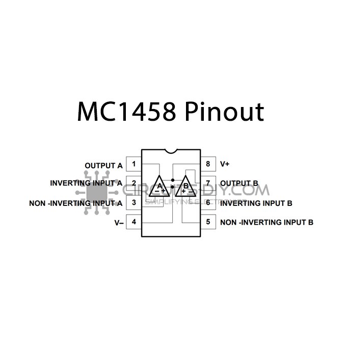
- Pinout, Package, and Datasheet Verification
- Modern Alternatives and Direct Replacements
- Frequently Asked Questions
- Specifications
- Datasheet PDF
The MC1458 is a general-purpose dual operational amplifier designed for basic analog signal processing, essentially serving as a dual version of the industry-standard 741 op-amp without offset null capability. Originally developed to provide robust, dual-channel amplification in a single package, it remains a heavily referenced component in legacy designs, educational circuits, and non-critical industrial control systems.
While it features internal frequency compensation and short-circuit protection, the MC1458 relies on a dated bipolar architecture that presents distinct challenges for modern electronics. Engineers evaluating this component—whether for maintaining a legacy bill of materials (BOM) or designing a simple control loop—must carefully weigh its ruggedness against its severe speed and precision limitations.
Core Architecture: Dual bipolar operational amplifier.
Primary Benefit: High reliability with no latch-up and built-in short-circuit protection.
Major Constraint: Slow dynamic response (0.5 V/µs slew rate) and lack of rail-to-rail output swing.
Sourcing Status: Widely available from STMicroelectronics, with pin-compatible variants from Texas Instruments and Onsemi.
Core Electrical Specifications and Operating Limits
Understanding the baseline capabilities of the MC1458 is the first step in determining if it can survive in your target application. Because it is a legacy part, its specifications require careful interpretation compared to modern op-amps.
Maximum Supply Voltage: ±18V. The device thrives in traditional split-supply environments (e.g., ±15V or ±12V).
Gain Bandwidth Product (GBP): 1 MHz. This defines the absolute upper limit of frequency response before the gain drops below unity.
Slew Rate: 0.5 V/µs. A critical bottleneck for large-signal bandwidth.
Input Offset Voltage: 6 mV (Max). By modern standards, this is a massive offset, making the part unsuitable for precision sensor amplification.
Operating Temperature Range: 0°C to 70°C. This commercial temperature grade restricts its use in harsh automotive or outdoor industrial environments.
Design Challenge 1: The "Dual 741" Architecture and Offset Errors
The most defining characteristic of the MC1458 is that it packs two 741-style amplifiers into a standard 8-pin package. To achieve this density, the original designers had to eliminate the offset null pins present on the single-channel 741.
For engineers, this creates an immediate design tradeoff. The bipolar input stage of the MC1458 draws significant bias current, which interacts with source impedances to generate offset voltage errors. Combined with a native maximum input offset voltage of 6 mV, the resulting DC error at the output can be substantial, especially in high-gain configurations.
If your design relies on high-impedance sources (like certain photodiode circuits or passive sensor bridges), the MC1458 will introduce unacceptable drift. Because there are no dedicated pins to trim this out, you are forced to implement external offset trimming circuitry—usually via a resistive summing network at the inverting input. If board space is tight, this defeats the purpose of using a cheap dual op-amp. In these scenarios, upgrading to a JFET-input op-amp with inherently lower bias current is the most practical engineering fix.
Design Challenge 2: Slew Rate and High-Frequency Distortion
The most severe limitation of the MC1458 is its 0.5 V/µs slew rate. Slew rate defines how fast the output voltage can change in response to an instantaneous change at the input.
In real-world terms, a 0.5 V/µs slew rate is entirely inadequate for modern high-frequency or high-fidelity audio applications. If you attempt to pass a 20 kHz audio signal at a high output amplitude, the amplifier simply cannot transition fast enough to keep up with the sine wave. The result is slew-induced distortion, where the output waveform begins to look like a triangle wave, introducing harsh harmonic artifacts.
When assessing the MC1458 for a BOM, you must calculate your required large-signal bandwidth. If your application involves anything faster than low-frequency control signals, sub-audio active filters, or slow DC integrators, the MC1458 will bottleneck your system. For audio or high-speed analog processing, migrating to a faster op-amp is strictly required.
Supply Voltage Headroom and Rail-to-Rail Limitations
Modern analog design heavily favors low-voltage, single-supply systems (e.g., 3.3V or 5V). The MC1458 is fundamentally incompatible with this design philosophy.
The device is not rail-to-rail at either the input or the output. The internal Darlington output stages require significant voltage headroom to operate linearly. Typically, the output voltage swing will clip 1.5V to 2V below the supply rails. If you power the MC1458 from a single 5V supply, your usable output range might only be 1.5V to 3.5V, severely limiting your dynamic range and signal-to-noise ratio.
To use the MC1458 effectively, you must provide sufficient supply voltage headroom. A traditional ±15V split supply is ideal, providing roughly a ±13V linear output swing. If your system architecture cannot support split supplies or high voltages, you must abandon the MC1458 in favor of a modern rail-to-rail input/output (RRIO) operational amplifier.
Typical Applications and Best Fit Scenarios
Despite its flaws, the MC1458 remains in active circulation because it is highly robust. The internal frequency compensation ensures stability at unity gain without external capacitors, and the built-in short-circuit protection prevents the device from destroying itself if the output is accidentally grounded.
Practical, successful applications for the MC1458 include: * Voltage followers (buffers): For low-frequency signals where the 0.5 V/µs slew rate is not a factor. * Active filters: Low-pass or band-pass filters in the sub-10 kHz range. * Integrators and differentiators: Used in slow analog control loops, PID controllers, or waveform generators where high precision is not critical. * Summing amplifiers: Mixing multiple slow analog signals, such as CV (control voltage) signals in analog synthesizers.
Pinout, Package, and Datasheet Verification
The MC1458 utilizes the industry-standard dual op-amp footprint, which is a massive advantage for lifecycle management and replacement.
Pin 1: Output A
Pin 2: Inverting Input A
Pin 3: Non-Inverting Input A
Pin 4: V- (Negative Supply or Ground)
Pin 5: Non-Inverting Input B
Pin 6: Inverting Input B
Pin 7: Output B
Pin 8: V+ (Positive Supply)
When verifying EDA libraries or footprints, ensure that the power pins (4 and 8) are correctly mapped, as reversing the polarity will instantly destroy the bipolar junctions. Additionally, since exact thermal derating depends heavily on your PCB copper area and the specific package type (e.g., DIP vs. SOIC), checking the manufacturer's specific thermal resistance curves is strictly required if you are driving heavy loads near the ±18V maximum supply.
Modern Alternatives and Direct Replacements
Because the MC1458 uses the standard dual op-amp pinout, replacing it on an existing PCB is usually a simple drop-in process, provided you account for the electrical differences. If you are hitting the performance limits of the MC1458, consider these direct alternatives:
1. Texas Instruments TL072 (The Speed & Impedance Upgrade)If the MC1458 is causing offset errors due to bias current, or distortion due to slow slew rates, the TL072 is the traditional upgrade path. It features a JFET input stage, dropping the bias current down to picoamps, and boasts a much faster 13 V/µs slew rate. It is highly recommended for audio upgrades.
2. Texas Instruments NE5532 (The Audio Fidelity Upgrade)For high-fidelity audio circuits where low noise is the primary concern, the NE5532 is heavily preferred over the MC1458. It offers superior bandwidth and extremely low voltage noise, though it does consume more quiescent power.
3. Texas Instruments LM358 (The Single-Supply Alternative)If you are trying to run a legacy circuit on a single supply (e.g., +5V or +12V) and the MC1458 is clipping, the LM358 is a better fit. While its slew rate is still quite slow, its input common-mode range includes ground, making it much friendlier for single-supply sensor reading.
4. Onsemi RC4558 (The Incremental Step)Often found alongside the MC1458 in legacy audio gear (like vintage guitar pedals), the RC4558 offers slightly better bandwidth and noise performance while retaining a similar bipolar character.
Frequently Asked Questions
Can I drop a TL072 directly into an MC1458 socket without changing the PCB footprint?Yes, both share the identical industry-standard dual op-amp pinout. However, ensure your power supply can handle the slightly different quiescent current requirements, and verify that the JFET inputs of the TL072 do not introduce phase reversal issues in your specific configuration if the inputs are driven near the negative rail.
Why is my MC1458 clipping well before my power supply voltage?The MC1458 is not a rail-to-rail amplifier. Its internal bipolar output stage requires roughly 1.5V to 2V of headroom from both the positive and negative rails. If you are powering it with 5V, your maximum output swing will be severely restricted.
How do I correct the offset voltage on the MC1458 if it lacks null pins?Because you cannot trim the internal stage like you can on a single 741, you must add an external high-value resistor connected to a potentiometer between the supply rails, injecting a small compensating current into the inverting input. If this takes up too much board space, the most efficient fix is replacing the IC with a precision op-amp.
Watch Tutorial: MC1458
Specifications
Datasheet PDF
- Datasheets :
 AD7689 8-Channel 16-Bit ADC: Performance Analysis and SPI Design Guide
17 March 2026322
 REG710NA-3/250: Pinout, Converter, Datasheet
18 February 2022927
 SST39SF040 4 Mbit MPF: Features, Datasheet and Timing Diagram
14 January 20222931
 BAS416 Diode: NXP BAS416, 75V, SOD 323, Datasheet PDF
17 February 20222036
 TIP117 PNP Power Transistor: Datasheet pdf, STM Darlington transistor
21 December 20213257
 INA226AIDGSR Amplifier: Pinout, INA226, INA226 vs INA260
10 March 20225518
 43025-0800 Micro-Fit 3.0 Receptacle Housing Dual Row: Drawing, Datasheet, and Equivalents
11 February 20222818
 tcmt4100 Transistor Output Optocouplers: Datasheet, Pinout, and Package
17 March 20221170
 What JEDEC JEP203 and JEP204 Actually Change for SiC Qualification Engineers and Component Buyers
29 July 2026584
 Electronic Components Distributor Utmel to Showcase at 2024 IPC APEX EXPO
10 April 20246096
 An Overview of Photoelectric Sensors
27 October 202510138
 What is Low Pass Filter
18 November 20217688
 STMicroelectronics: The European Powerhouse in Silicon Carbide Semiconductor Technology
05 October 20233517
 What is a USB Type-C Connector?
28 October 20256997
 FPGA in Industry and Communication: Key Players, Technologies, and Future Trends
07 March 20252551
 Manifold Absolute Pressure (MAP) Sensor: Working Principles, Structure, and Types
31 March 202549348
STMicroelectronics
In Stock
United States
China
Canada
Japan
Russia
Germany
United Kingdom
Singapore
Italy
Hong Kong(China)
Taiwan(China)
France
Korea
Mexico
Netherlands
Malaysia
Austria
Spain
Switzerland
Poland
Thailand
Vietnam
India
United Arab Emirates
Afghanistan
Åland Islands
Albania
Algeria
American Samoa
Andorra
Angola
Anguilla
Antigua & Barbuda
Argentina
Armenia
Aruba
Australia
Azerbaijan
Bahamas
Bahrain
Bangladesh
Barbados
Belarus
Belgium
Belize
Benin
Bermuda
Bhutan
Bolivia
Bonaire, Sint Eustatius and Saba
Bosnia & Herzegovina
Botswana
Brazil
British Indian Ocean Territory
British Virgin Islands
Brunei
Bulgaria
Burkina Faso
Burundi
Cabo Verde
Cambodia
Cameroon
Cayman Islands
Central African Republic
Chad
Chile
Christmas Island
Cocos (Keeling) Islands
Colombia
Comoros
Congo
Congo (DRC)
Cook Islands
Costa Rica
Côte d’Ivoire
Croatia
Cuba
Curaçao
Cyprus
Czechia
Denmark
Djibouti
Dominica
Dominican Republic
Ecuador
Egypt
El Salvador
Equatorial Guinea
Eritrea
Estonia
Eswatini
Ethiopia
Falkland Islands
Faroe Islands
Fiji
Finland
French Guiana
French Polynesia
Gabon
Gambia
Georgia
Ghana
Gibraltar
Greece
Greenland
Grenada
Guadeloupe
Guam
Guatemala
Guernsey
Guinea
Guinea-Bissau
Guyana
Haiti
Honduras
Hungary
Iceland
Indonesia
Iran
Iraq
Ireland
Isle of Man
Israel
Jamaica
Jersey
Jordan
Kazakhstan
Kenya
Kiribati
Kosovo
Kuwait
Kyrgyzstan
Laos
Latvia
Lebanon
Lesotho
Liberia
Libya
Liechtenstein
Lithuania
Luxembourg
Macao(China)
Madagascar
Malawi
Maldives
Mali
Malta
Marshall Islands
Martinique
Mauritania
Mauritius
Mayotte
Micronesia
Moldova
Monaco
Mongolia
Montenegro
Montserrat
Morocco
Mozambique
Myanmar
Namibia
Nauru
Nepal
New Caledonia
New Zealand
Nicaragua
Niger
Nigeria
Niue
Norfolk Island
North Korea
North Macedonia
Northern Mariana Islands
Norway
Oman
Pakistan
Palau
Palestinian Authority
Panama
Papua New Guinea
Paraguay
Peru
Philippines
Pitcairn Islands
Portugal
Puerto Rico
Qatar
Réunion
Romania
Rwanda
Samoa
San Marino
São Tomé & Príncipe
Saudi Arabia
Senegal
Serbia
Seychelles
Sierra Leone
Sint Maarten
Slovakia
Slovenia
Solomon Islands
Somalia
South Africa
South Sudan
Sri Lanka
St Helena, Ascension, Tristan da Cunha
St. Barthélemy
St. Kitts & Nevis
St. Lucia
St. Martin
St. Pierre & Miquelon
St. Vincent & Grenadines
Sudan
Suriname
Svalbard & Jan Mayen
Sweden
Syria
Tajikistan
Tanzania
Timor-Leste
Togo
Tokelau
Tonga
Trinidad & Tobago
Tunisia
Turkey
Turkmenistan
Turks & Caicos Islands
Tuvalu
U.S. Outlying Islands
U.S. Virgin Islands
Uganda
Ukraine
Uruguay
Uzbekistan
Vanuatu
Vatican City
Venezuela
Wallis & Futuna
Yemen
Zambia
Zimbabwe


