

 Product
 Brand
Brand Articles
 Tools
Tools
1N5822 Schottky Diode: Pinout, Datasheet, and Applications

Schottky Diode Rectifier Fast Recovery =< 500ns, > 200mA (Io) 525mV @ 3A 150°C Max 2mA @ 40V 2-Termination Tape & Box (TB) DO-201AD, Axial Through Hole


Schottky Diode Rectifier Fast Recovery =< 500ns, > 200mA (Io) 525mV @ 3A 150°C Max 2mA @ 40V 2-Termination Tape & Box (TB) DO-201AD, Axial Through Hole
The 1N5822 is a Schottky diode that has very low forward drop voltage VF which makes it ideal for fast switching applications at lower current ratings.

1N5822 Schottky Diodes & Rectifiers STMicroelectronics
- Quick answer
- What is a 1N5822?
- 1N5822 pinout and polarity
- 1N5822 specifications with test conditions
- What 3 A and 40 V really mean
- Package and mechanical dimensions
- Lifecycle and manufacturer differences
- Typical applications and selection checks
- How to compare possible 1N5822 replacements
- Is LEO1N5822 the same as the axial 1N5822?
- FAQ
- Official sources
- Specifications
- Datasheet PDF
Quick answer
The 1N5822 is an axial Schottky barrier rectifier commonly specified for 3 A average forward current and 40 V repetitive peak reverse voltage in a DO-201AD package. Its banded end is the cathode. Typical uses include low-voltage converter outputs, freewheeling paths, and reverse-polarity protection.
Those headline values are not unconditional. The 3 A rating depends on the manufacturer's thermal test setup, and the 40 V value is a maximum repetitive reverse-voltage rating rather than a recommended operating target. The base number also does not make every manufacturer's version interchangeable. Design and source against the exact manufacturer, ordering suffix, datasheet revision, and circuit conditions.
What is a 1N5822?
The 1N5822 belongs to the 1N5820/1N5821/1N5822 axial Schottky family. In Vishay's family datasheet, the three devices share a 3 A current class and DO-201AD package, while their repetitive peak reverse-voltage ratings increase from 20 V to 30 V and 40 V. The 1N5822 is the 40 V member of that specific family.
Schottky rectifiers are useful in low-voltage power paths because their relatively low forward drop can reduce conduction loss and their reverse recovery is fast. The tradeoff is that reverse leakage rises with temperature. A real design must therefore consider forward voltage, reverse leakage, duty cycle, temperature, and switching stress together.

1N5822 pinout and polarity
An axial 1N5822 has two terminals. The unbanded lead is the anode (A), and the banded lead is the cathode (K).
| Terminal | Identification | Function |
|---|---|---|
| Anode (A) | Unbanded end | Conventional forward current enters here when the diode is forward biased. |
| Cathode (K) | Banded end | Conventional forward current leaves here; the body band marks this terminal. |
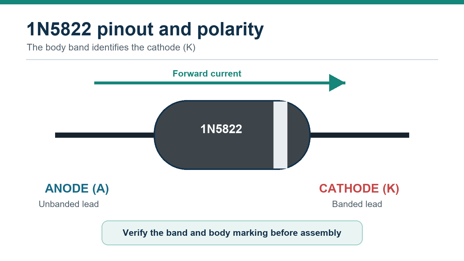
For normal forward conduction, the anode is at a higher potential than the cathode. In reverse-blocking service, the cathode is at the higher potential. Do not infer polarity from the orientation of a product photograph; verify the physical band and the exact part marking.
1N5822 specifications with test conditions
The table keeps Vishay's current family datasheet separate from ST's legacy axial 1N5822 datasheet. These values are manufacturer-specific and should not be blended into a universal specification.
| Parameter | Vishay 1N5822 | Legacy ST 1N5822 | Design note |
|---|---|---|---|
| Device type | Single Schottky barrier rectifier | Axial power Schottky rectifier | Verify manufacturer and ordering suffix. |
| Package | DO-201AD | DO-201AD | Check the exact mechanical drawing. |
| Repetitive peak reverse voltage, VRRM | 40 V | 40 V | This is a limit, not a recommended operating point. |
| Maximum DC blocking voltage | 40 V | 40 V | Allow margin for tolerance, ringing, and transients. |
| Average forward current, IF(AV) | 3.0 A at TL = 95 deg C and 9.5 mm lead length | 3 A at TL = 100 deg C and duty cycle = 0.5 | The headline current depends on thermal conditions. |
| Peak forward surge current, IFSM | 80 A, 8.3 ms single half sine-wave, superimposed on rated load | 80 A, 10 ms sinusoidal pulse | A surge test is not a continuous-current rating. |
| Maximum instantaneous VF at 3 A | 0.525 V at 25 deg C; 300 us pulse, 1% duty cycle | 0.525 V at 25 deg C; 380 us pulse, duty cycle below 2% | Use the curve for other currents and temperatures. |
| Maximum instantaneous VF at 9.4 A | 0.950 V under the Vishay pulse test | 0.950 V under the ST pulse test | This is a pulsed electrical limit. |
| Maximum reverse current at rated blocking voltage | 2.0 mA at 25 deg C; 20 mA at 100 deg C | 2 mA at 25 deg C; 20 mA at 100 deg C | Leakage and reverse loss rise with temperature. |
| Maximum junction temperature | 125 deg C | 150 deg C | This cross-vendor difference can change thermal design. |
Why the forward-voltage value is often quoted incorrectly
The family tables contain several forward-voltage values. In both cited datasheets, 0.525 V is the maximum 1N5822 value at 3 A under the stated room-temperature pulse test. The lower 0.475 V value belongs to the 1N5820 column, not the 1N5822 column. A circuit's actual forward drop changes with current, junction temperature, waveform, and manufacturer.
What 3 A and 40 V really mean
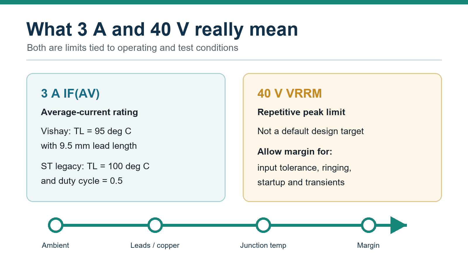
The 3 A value is thermally conditioned. Vishay specifies it at a 95 deg C lead temperature with a defined lead length; legacy ST uses a 100 deg C lead temperature and a 0.5 duty cycle. Different lead length, copper area, airflow, ambient temperature, or waveform can produce a different junction temperature. Use the selected datasheet's derating curve and thermal model.
The 40 V VRRM value is a maximum repetitive peak reverse-voltage rating. It is not an instruction to operate continuously at 40 V. Check input tolerance, inductive ringing, switching overshoot, startup, and fault transients, then choose adequate voltage margin for the actual circuit.
Package and mechanical dimensions
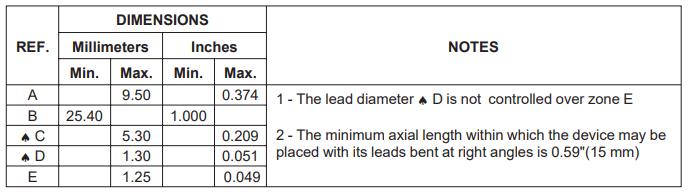
Vishay's DO-201AD drawing specifies a body length of 7.2 mm to 9.5 mm, body diameter of 4.8 mm to 5.3 mm, lead diameter of 1.22 mm to 1.32 mm, and minimum straight lead length of 25.4 mm on each side. Lead forming, board spacing, and heat flow can all affect the installed result.

Lifecycle and manufacturer differences
ST marks its axial 1N5822 product page Obsolete - Out of Production. That status applies to ST's axial product, not automatically to every supplier using the 1N5822 base designation. Vishay maintains an official product page and family datasheet for its 1N5820/1N5821/1N5822 devices.
For maintenance work, record the manufacturer, complete ordering code, package, qualification level, and lifecycle status. For a new design, confirm current availability through an authorized supply channel and retain the chosen datasheet revision with the bill of materials.
Typical applications and selection checks
Manufacturer documentation identifies common uses such as low-voltage high-frequency inverter rectification, freewheeling paths, DC/DC converter outputs, reverse-polarity protection, switch-mode power-supply outputs, and low-voltage battery-charger power paths.
These are application categories, not ready-made circuits. For each design:
Identify the exact device. Record the manufacturer and full ordering suffix.
Measure reverse stress. Include tolerance, ringing, startup, load dump, and other transients.
Model the current waveform. Separate average, RMS, peak, and surge current.
Estimate forward loss. Use the datasheet curve at the expected current and junction temperature.
Estimate reverse loss. Use leakage data at the expected reverse voltage and temperature.
Close the thermal loop. Check lead temperature, mounting geometry, ambient temperature, and transient thermal impedance.
Check mechanics and polarity. Verify body dimensions, lead forming, clearances, and the cathode band.
Validate the circuit. Test worst-case line, load, temperature, startup, shutdown, and fault conditions.
How to compare possible 1N5822 replacements
A proposed device is not a drop-in replacement merely because it shares the 1N5822 name or appears in a distributor cross-reference. Compare the exact datasheets and verify VRRM, DC blocking voltage, average/RMS/peak current, surge waveform, forward-voltage curves, reverse leakage over temperature, junction limit, package dimensions, polarity, qualification, lifecycle, and supply source.
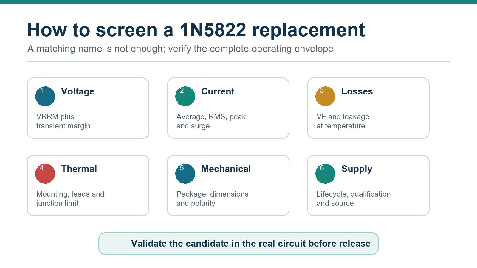
Within Vishay's axial family, 1N5820 and 1N5821 are rated for 20 V and 30 V VRRM. They cannot satisfy a design that genuinely requires the 1N5822's 40 V rating. A same-number device from another manufacturer may be a candidate for validation, but the 125 deg C versus 150 deg C junction-limit difference shows why the complete specifications must be compared.
Is LEO1N5822 the same as the axial 1N5822?
No. ST's LEO1N5822 is a rad-hard 3 A, 40 V Schottky rectifier in a SOD128Flat surface-mount package for low-earth-orbit and high-reliability systems. It is not the same mechanical product as ST's obsolete axial DO-201AD 1N5822. Package, qualification, radiation data, thermal behavior, and ordering information all differ.
FAQ
What is the 1N5822 pinout?
It is a two-terminal axial diode. The unbanded lead is the anode, and the banded lead is the cathode.
What are the main 1N5822 ratings?
For the cited Vishay device, the headline ratings are 40 V VRRM and 3 A IF(AV) in DO-201AD. The 3 A value is tied to a 95 deg C lead-temperature condition and a specified lead length.
What is the forward voltage of a 1N5822?
Vishay specifies a maximum instantaneous forward voltage of 0.525 V at 3 A and 25 deg C using a 300 us pulse at 1% duty cycle. Use the datasheet curve for other currents and temperatures.
Can a 1N5822 handle 3 A continuously?
Only when the selected manufacturer's mounting and thermal conditions keep the junction within its limit. The current rating cannot be separated from lead temperature, mounting, ambient conditions, and waveform.
What can replace a 1N5822?
No universal replacement is guaranteed. A candidate must meet the circuit's voltage, current, surge, loss, temperature, package, qualification, lifecycle, and sourcing requirements, then be validated in the actual application.
Is the ST 1N5822 still active?
ST marks its axial 1N5822 obsolete and out of production. Check other manufacturers separately; one supplier's lifecycle status does not define every device sold under the base number.
Is 1N5822 suitable for RF signal detection?
The cited 1N5822 documentation describes a power rectifier for power-conversion applications. RF detector circuits normally use small-signal devices selected for capacitance, impedance, frequency, and signal level. Do not infer RF suitability from the word Schottky alone.
Official sources
Specifications
Datasheet PDF
- Datasheets :
1.What is 1N5822?
Schottky diodes have very low forward drop voltage VF which makes them ideal for fast switching applications at lower current ratings. 1N5822 have forward voltage drop of minimum 0.525 V that is it requires 0.525 V to conduct in forward biased direction.
2.Is the cathode for schottky diode hotter than the anode, as is common for most diodes, or is it reverse polarity?
I have never seen a diode with a thermal pad on the anode. Always on the cathode if one exists.
3.Is it okay to substitute 1A 40V 1N5819 Schottky with 40V 3A 1N5822 and what can go wrong with that setup?
They have nearly the same VF and Rth-JA at the same conditions. But 1N5822 has higher leakage current level. So the answer is: it depends on usage and required electrical performance.
If the diode is a part of an SMPS (e.g. buck converter), or it's used to protect semiconductors against spikes (e.g. placing across the coil of a relay), or simply it's used just for a reverse polarity protection purpose then yes, you can safely use 5822 in place of a 5819. But if it's used in a power-OR of a circuit including backup battery then the leakage current may be a problem.
The size should be considered as well since 5822 is bigger. It also requires bigger holes (1.5mm dia) for proper mounting and soldering.
 IRF5210 Power MOSFET: Datasheet, Price, Pinout
18 March 20225535
 AD580 Three Terminal Voltage Reference: A Reliable Solution for Precise Voltage Regulation
06 March 2024316
 ATTINY13V CMOS 8-bit Microcontroller: Features, Pinout and Datasheet
13 January 20221411
 STMPS2141STR Microcontroller: 40μA,500mA, Pinout and Features
16 February 20221253
 RH850/F1L Microcontroller for Automotive Body Applications: Datasheet Overview
29 February 2024362
 M95040-W Serial SPI bus EEPROM: Pinout, Equivalent and Datasheet
14 January 20225761
 A Comprehensive Guide to the Analog Devices Inc. 5962-8773802GA Linear Amplifier
06 March 2024186
 Everything you need to know about DRV8825 Stepper Motor Driver
28 April 20229664
 Working Principle and Development of Magnetic Sensors
31 October 20254817
 What is a Server CPU?
22 December 202112129
 How to Select the Most Accurate Shunt Resistor for Your Circuit
06 June 20254914
 Review of Flux-Concentrated Transverse Flux Permanent Magnet Machines
15 December 20232480
 What is Instrument Transformer?
08 January 20227943
 Current Shunt Resistor Pulse Rating Selection: Sizing for Inrush Energy, TCR Drift, and Kelvin Connections
12 September 2026320
 What is Mini LED?
08 December 20206675
 Introduction to Distribution Transformer
24 February 20219451
STMicroelectronics
In Stock: 5400
United States
China
Canada
Japan
Russia
Germany
United Kingdom
Singapore
Italy
Hong Kong(China)
Taiwan(China)
France
Korea
Mexico
Netherlands
Malaysia
Austria
Spain
Switzerland
Poland
Thailand
Vietnam
India
United Arab Emirates
Afghanistan
Åland Islands
Albania
Algeria
American Samoa
Andorra
Angola
Anguilla
Antigua & Barbuda
Argentina
Armenia
Aruba
Australia
Azerbaijan
Bahamas
Bahrain
Bangladesh
Barbados
Belarus
Belgium
Belize
Benin
Bermuda
Bhutan
Bolivia
Bonaire, Sint Eustatius and Saba
Bosnia & Herzegovina
Botswana
Brazil
British Indian Ocean Territory
British Virgin Islands
Brunei
Bulgaria
Burkina Faso
Burundi
Cabo Verde
Cambodia
Cameroon
Cayman Islands
Central African Republic
Chad
Chile
Christmas Island
Cocos (Keeling) Islands
Colombia
Comoros
Congo
Congo (DRC)
Cook Islands
Costa Rica
Côte d’Ivoire
Croatia
Cuba
Curaçao
Cyprus
Czechia
Denmark
Djibouti
Dominica
Dominican Republic
Ecuador
Egypt
El Salvador
Equatorial Guinea
Eritrea
Estonia
Eswatini
Ethiopia
Falkland Islands
Faroe Islands
Fiji
Finland
French Guiana
French Polynesia
Gabon
Gambia
Georgia
Ghana
Gibraltar
Greece
Greenland
Grenada
Guadeloupe
Guam
Guatemala
Guernsey
Guinea
Guinea-Bissau
Guyana
Haiti
Honduras
Hungary
Iceland
Indonesia
Iran
Iraq
Ireland
Isle of Man
Israel
Jamaica
Jersey
Jordan
Kazakhstan
Kenya
Kiribati
Kosovo
Kuwait
Kyrgyzstan
Laos
Latvia
Lebanon
Lesotho
Liberia
Libya
Liechtenstein
Lithuania
Luxembourg
Macao(China)
Madagascar
Malawi
Maldives
Mali
Malta
Marshall Islands
Martinique
Mauritania
Mauritius
Mayotte
Micronesia
Moldova
Monaco
Mongolia
Montenegro
Montserrat
Morocco
Mozambique
Myanmar
Namibia
Nauru
Nepal
New Caledonia
New Zealand
Nicaragua
Niger
Nigeria
Niue
Norfolk Island
North Korea
North Macedonia
Northern Mariana Islands
Norway
Oman
Pakistan
Palau
Palestinian Authority
Panama
Papua New Guinea
Paraguay
Peru
Philippines
Pitcairn Islands
Portugal
Puerto Rico
Qatar
Réunion
Romania
Rwanda
Samoa
San Marino
São Tomé & Príncipe
Saudi Arabia
Senegal
Serbia
Seychelles
Sierra Leone
Sint Maarten
Slovakia
Slovenia
Solomon Islands
Somalia
South Africa
South Sudan
Sri Lanka
St Helena, Ascension, Tristan da Cunha
St. Barthélemy
St. Kitts & Nevis
St. Lucia
St. Martin
St. Pierre & Miquelon
St. Vincent & Grenadines
Sudan
Suriname
Svalbard & Jan Mayen
Sweden
Syria
Tajikistan
Tanzania
Timor-Leste
Togo
Tokelau
Tonga
Trinidad & Tobago
Tunisia
Turkey
Turkmenistan
Turks & Caicos Islands
Tuvalu
U.S. Outlying Islands
U.S. Virgin Islands
Uganda
Ukraine
Uruguay
Uzbekistan
Vanuatu
Vatican City
Venezuela
Wallis & Futuna
Yemen
Zambia
Zimbabwe
![STPS340U]() STPS340U
STPS340USTMicroelectronics
![STTH112U]() STTH112U
STTH112USTMicroelectronics
![STPS2H100A]() STPS2H100A
STPS2H100ASTMicroelectronics
![BAT54JFILM]() BAT54JFILM
BAT54JFILMSTMicroelectronics
![STPS2150A]() STPS2150A
STPS2150ASTMicroelectronics
![STTH1R06A]() STTH1R06A
STTH1R06ASTMicroelectronics
![STPS0520Z]() STPS0520Z
STPS0520ZSTMicroelectronics
![TMMBAT48FILM]() TMMBAT48FILM
TMMBAT48FILMSTMicroelectronics
![BAT20JFILM]() BAT20JFILM
BAT20JFILMSTMicroelectronics
![BAT41KFILM]() BAT41KFILM
BAT41KFILMSTMicroelectronics


