
 Product
 Brand
Brand Articles
 Tools
Tools
How do We Select Automotive Relays?

Basic Automotive Relay Operation and Simple Wiring
Catalog
I What is Automotive Relay?
Automotive relays are relays used in automobiles. Such relays have high switching load power, high shock resistance, and vibration resistance. Most power supplies in automobiles use 12V, and most of the coil voltages are designed to be 12V. Because it's supplied by the battery, the voltage is unstable. The pull-up voltage V≤60%VH (rated working voltage), and the coil overvoltage is allowed to reach 1.5VH. Besides, the power consumption of the coil is relatively large, generally 1.6-2W, and the temperature rise is relatively high.
The environmental requirements are quite harsh: in the engine compartment, the ambient temperature range is -40℃-125℃, and the ambient temperature range of other locations is -40℃-85℃. The relay used in the engine compartment must withstand sand, dust, water, and salt, oil, vibration, and shock.
II Working Principle of Automotive Relay
When a certain voltage or current is applied to both ends of the electromagnetic relay coil, the magnetic flux generated by the coil passes through the magnetic circuit composed of the core, yoke, armature, and working air gap.
Under the action of the magnetic field, the armature is attracted to the pole surface of the core. Thus, the normally closed contact is forced to open, and the normally open contact is closed. When the voltage or current at both ends of the coil is less than a certain value, and the mechanical force is greater than the electromagnetic attraction, the armature returns to the initial state. The normally open contact is disconnected, and the normally closed contact is turned on.
Then, the automobile relay can be regarded as an assembly composed of two parts: the control circuit with coils and the main circuit with the contact. In the control circuit of the relay, there is only a small working current. This is because the contact capacity of the control switch is small, and it cannot be used to directly control the load with large power consumption, instead, it can only be controlled by the contact of the relay.
The relay is not only a control switch but also a control object (actuator). Take the fuel pump relay as an example. It is the control switch of the fuel pump, but the coil of the fuel pump relay can only form a loop through the ground point of the electronic control unit when the driving transistor in the electronic control unit is turned on.
III Automotive Relay Components
The automobile relay is composed of a magnetic circuit system, contact system, and restoring mechanism. The magnetic circuit system is composed of an iron core, yoke, armature, coil, and other parts. The contact system is composed of static reeds, moving reeds, contact bases, and other parts. The restoring mechanism is composed of a restoring reed or a tension spring.

Figure 1. Automotive Relay Structure
IV Installation Method
1. Installation Direction
If the installation direction is the same as the impact resistance direction of the relay, the performance of the relay can be fully utilized.
It is recommended to make the impact direction perpendicular to the direction of the movement of the contact and armature, which can effectively improve the vibration and impact resistance of the normally closed contact in the non-exciting state.
When installing, make the contact axis of the relay parallel to the ground, which can avoid contact splashes and carbides falling on the contact surface, improving contact reliability.
For multiple groups of relays, the small load contacts should be not under the large load contacts.
2. Short-distance Installation
When multiple relays are installed in close distance, it will cause abnormal heating. Generally, a 2mm spacing is recommended. Polarity or magnetic holding relays installed with close distance will affect the operating voltage.
3. Housing with the Relay
You cannot remove the shell for installation. To prevent loosening, damage, and deformation, please use spring washers. The torque should be screw up within the range of 0.5-70N·m.
4. The recommended insertion strength of the plug-in relay is 40-70N.
5. Products that meet the same load requirements have different dimensions. According to the allowable installation space, products with low height or small installation area can be selected.
6. The installation methods of automotive relays include PCB board, ISO socket installation, ISO 280 socket installation, and shell fixing.
For the relays that are small and not frequently replaced, the PCB board type is generally used, and for the relays that are frequently replaced, the socket installation method is selected.
For relays whose main circuit current exceeds 20A, the socket quick-connect type is generally used to prevent large currents passing through the circuit board, causing heat damage to the circuit board (except for short-term working relays).
For large-volume relays, you can choose the shell mounting type to prevent damage to the mounting feet under shock and vibrations.
V Maintenance of Automotive Relay
1. Welding Process
(1) Soldering Flux
PCB board-type non-plastic-packaged relays are very susceptible to contamination by the soldering flux. It is recommended to use flux-resistant or plastic-encapsulated relays to prevent flux gas from entering the gap between the lead-out end and the base and the shell. For flux-resistant relays, use preheating and drying (100℃ for 1 minute) can further prevent flux penetration.

Figure 2. Soldering Flux
(2) Welding Methods
When using soldering flux or automatic soldering, be careful not to damage the performance of the relay. Flux-resistant relays or plastic-encapsulated relays can be applied for dip soldering or wave soldering processes, but the maximum soldering temperature and time should be controlled depending on the selected relay.
1) Wave soldering: The recommended soldering temperature is 240℃-260℃, and the time is about 5 seconds. The best soldering temperature is 250℃.
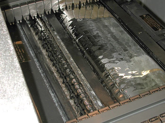
Figure 3. Wave Soldering Machine
2) Manual welding: The recommended welding temperature is 300℃-350℃, and the welding time should be controlled within 2 seconds.
3) Cooling: The heating of the relay caused by the soldering process can be relieved by cooling at the end of the process, so do not change the temperature suddenly, especially to avoid cold shock to the thermal relay.
2. Cleaning Process
No-clean flux should be used for soldering as much as possible, and the overall cleaning of the relay should be avoided.
Prevent cleaning agents from entering the relay and causing failure. Also, it is forbidden to use ultrasonic cleaning to avoid cold welding of contacts, broken enameled wires, and other structural damage caused by ultrasonic energy.
After cleaning and drying, ventilation treatment should be carried out immediately to bring the temperature of the relay to room temperature.
Coating preservation agent:
Sometimes in order to ensure the moisture resistance and high insulation of the circuit board, the circuit board must be coated with a preservation agent. A softer glue without silicon should be used. The gluing process should prevent the relay from generating negative pressure and, or the preservation agent will be sucked.
3. Troubleshooting
(1) Simple Judgment for Relay Performance
Turn on the ignition switch, and then use your ears or stethoscope to listen to if there is a pull-in sound in the control relay, or feel whether the relay is vibrating with your hands. If there is, the relay is basically working normally, and the electrical appliance is not working due to other reasons; Otherwise, it means that the relay works abnormally.
You can also unplug the relay for testing. For example, if the air conditioner compressor does not work, you can start the engine, and then turn on the blower switch and the air conditioner switch. Then unplug the connector of the air conditioner compressor relay for judgment.
If the sound of the relay can be heard, and the engine speed drops significantly when the relay is unplugged, and the engine speed increases when the relay is inserted, it means that the air conditioner compressor relay and its control circuit are normal.
Regarding the location of the relay, all relays and fuses marked with a dot-dash line on the schematic circuit diagram are generally arranged in the central power distribution box.
(2) Common Faults of Relays
Common fault phenomena of relays include coil burnout, the short circuit between turns (insulation aging), contact ablation, thermal decay, and the inability to adjust the initial operating current.
1) The relay coil is burned out. In order to prevent this fault, when repairing, maintaining, and welding, if the temperature may exceed 80°C, we should remove the temperature-sensitive relay and electronic control unit.
2) Contact ablation. For example, the relay of the air conditioner condenser fan of the Jinbei Hiace car (using the 491Q-ME engine) is just below the glass-cleaning spray pipe. If the spray pipe ruptures, the cleaning fluid will leak to the relay, making the normally open contact rusty and cannot be disconnected, which will cause the air conditioner condenser fan to run constantly. Therefore, water should be strictly prevented from entering the relay.
3) Try to reduce the contact resistance of the relay contacts. The contact resistance between the contacts of the automotive relay is mainly composed of the shrink resistance and the surface film resistance.
The contact resistance is related to the contact form, material properties, and surface processing of the contact. Therefore, when the contact pressure is constant, you can improve the contact state and improve the contact material to reduce the contact resistance.
4. Storage Environment
Avoid direct sunlight and keep normal temperature, humidity, and pressure.
● Temperature: 10℃-35℃
● Humidity: 5-85%RH
● Air Pressure: 86-106kPa
In a high temperature and high humidity environment, when the ambient temperature changes sharply, condensation may form inside the relay. In particular, condensation is prone to occur when shipping by ship, so please pay attention to the transportation environment.
Condensation is the phenomenon of water vapor condensing into water droplets when the temperature changes from high temperature to low temperature in a high temperature and high humidity environment, or when the temperature changes from a low temperature to a high temperature and high humidity environment. Condensation will cause insulation degradation, coil corrosion, disconnection, rust, etc.
Low-temperature icing: In dew and high-humidity environments, when moisture is attached to the relay, water freezes when the temperature drops below the freezing point. Icing may cause adhesion of movable parts, delay of action, or ice cubes between the contacts, causing the contacts to malfunction.
In a low temperature and low humidity environment, plastics may become brittle.
When stored for a long time in a high temperature, high humidity environment containing organic gas and sulfide gas, sulfide film, and oxide film will be formed on the contact surface, which will cause unstable contact and contact failure. Please pay attention to the packaging form to minimize the influence of humidity, organic gas, sulfide gas, etc.
The relay should be stored and installed in a clean environment. Please use a dust cover or plastic-encapsulated relay in an environment with dust pollution.
Also, monitor the storage temperature and try to avoid excessive storage time of the relay.
If a large drop impact is applied to the relay, it may cause functional failure. Please pay attention to the integrity of the packaging material.
The relay is packaged in a long tube. When the number of relays is small, if the limit is missing, it will slip and affect the appearance and characteristics of the relay.
VI How do We Select Automotive Relays?
When selecting automotive relays, analysis and research can be carried out according to the following points: shape and installation method; input parameters; output parameters; environmental conditions; electromagnetic compatibility; installation and use requirements.
1. Parameter Selection
(1) Input Parameter Selection
The input parameters of automobile relays are 12VDC input parameters, 24VDC input parameters, 12VDC pulse input parameters, 24VDC pulse input parameters.

Figure 4. 12VDC Automotive Relay
Consider the following parameters when selecting:
● Coil rated voltage
● Coil power consumption
● Action voltage,
● Release voltage
● Maximum continuous current
● Coil resistance
● Coil temperature rise
● The pulse width of the pulse input parameter (for magnetic latching relay)
1) Ambient temperature
The operating environment temperature and the temperature rise of the coil affect the operating voltage. The temperature is generally divided into engine compartment temperature(maximum temperature requirement is 125℃) and cockpit temperature (maximum temperature requirement is 85℃).
The relay coil resistance varies with temperature, which has an obvious influence on relay action and release voltage. The resistance of the coil will increase by 4‰ for every 1℃ increase in temperature. When the relay coil is energized for a while, the coil heats up. At this time, the relay contact switches, and its operating voltage is higher than the cold operating voltage.
2) Operating voltage
When using transistors and integrated circuits to drive relays, pay attention to the voltage drop of transistors and integrated circuits and the destructive effect of the relay coil counter EMF on the transistors and integrated circuits.
3) Coil rated voltage
After the normally open contact of the relay is closed, a voltage above the minimum operating voltage is generally applied to the coil. Low holding voltage is not recommended for automotive relays, because it will weaken the product's vibration resistance, and when the car is violently jolting, the malfunction may occur.
4) The maximum working voltage of the coil
In order to meet the requirements of low operating voltage (60% rated voltage), automotive relays are generally designed with a voltage value with high power consumption, generally be less than 120% of the rated voltage.
When the voltage reaches 130% rated voltage or above, contact the relay manufacturer for technical support. Especially when the relay is used under high temperature, the coil temperature will be too high and the aging will be accelerated, eventually, the coil insulation layer will be damaged, and there will be a short circuit between turns, causing failure.
5) Release voltage: The release voltage of automobile relays is generally 10% of the rated voltage. When the remaining voltage on the line is too large, the relay will not release.
(2) Output Parameter
The following parameters should be considered when selecting the relay output parameters:
● Number of contact groups
● Contact form
● Contact load
● Contact material
● Electrical life
● Mechanical life
(3) Time Parameter
The following parameters should be considered when selecting the time parameters of the relay:
● Suction time
● Release time
● Suction rebound time
● Release rebound time
2. Environmental Selection
The following environmental parameters should be considered when selecting the relay:
(1) Temperature
1) Under high-temperature conditions, the insulating material softens and melts. Under low-temperature conditions, the material cracks and the insulation resistance performance decreases, leading to failure. Choosing engineering plastics with excellent performance can meet the requirements.
2) Under the alternating action of high and low temperature, the structure will loosen and the position of the movable parts will change, resulting in out-of-control suction and release, and poor contact or non-contact
3) At low temperatures, the water vapor inside the relay will condense and freeze, causing the insulation performance to decrease.
4) Under high-temperature conditions, the resistance of the coil increases, and the suction voltage increases correspondingly, resulting in non-sucking or poor sucking, causing the relay to fail.
5) Under high temperatures, when the contacts switching power loads, the arc breaking capacity is reduced, and contact corrosion and metal transfer increase. Besides the possibility of failure increases, and life is shortened.
(2) Hot and Humid
The hot and humid condition poses a threat to the performance of the relay, and the specific manifestations are as follows:
1) Long-term under hot and humid conditions will directly degrade the insulation resistance level, leading to complete failure. Especially in the long-term bare storage or use, if the relay insulation is polluted by sand and dust and then exposed to the hot and humid condition, it will cause insulation failure.
2) Under damp and hot conditions, the coil of the non-sealed relay is broken due to electrochemical corrosion or mildew, and the contacts are electrochemically corroded and oxidized. The corrosion rate of metal parts increases significantly, the performance of the relay deteriorates, and the working reliability deteriorates, resulting in complete failure.
3) Under hot and humid conditions, when the contacts switch loads with electrics, the arcing phenomenon is aggravated, shortening the electrical life.
For electronic products used in the tropics and subtropics, the heat and humidity issues must be fully considered when designing and selecting materials.
(3) Sand and Dust
The relay failure caused by the sand and dust pollution has not attracted enough attention from users.
Under natural environmental conditions or general industrial workshops, especially the electronic devices used on automobiles, sand and dust will often penetrate into the relay through the heat emission holes and cracks.
After the accumulation, dust accumulates and causes the rotation (sliding) of the components to be not effective and stuck. The electrical contact also fails, and under the action of moisture, the metal parts corrode, and the insulation performance of the insulating parts is reduced, resulting in failure.
Some electrical protection relays and automotive relays are qualified before delivery. After one or two years of operation, the relays continue to fail. The hazards of sand and dust pollution must be fully considered during design and use.
(4) Pollution of the Chemical Atmosphere
Organic vapor, oxygen, sulfur dioxide, salt spray, etc. in the ambient atmosphere have corrosive effects on relay contacts, metal parts, coils, and insulating parts, resulting in poor electrical contact, leading to corrosion and disconnection of coil leads and decreasing the insulation level.
Chemical harmful gases are ubiquitous in nature, but the types of harmful gases (steam) are different on different occasions. Taking technological measures can reduce and avoid erosion, but the cost will increase greatly. Such as military sealed relays, through long-term high-temperature vacuum baking, filling the inner cavity of the relay with high-purity N2, and using an electron beam (or laser) for sealing welding, the leakage rate can reach 10-8pa.cm3/s.
Civil relays are limited by price. Generally, only plastic packages are used to relieve the corrosion from harmful gases (vapor) in the atmosphere. When using, according to the size of the relay load and the environment, the process holes can be opened appropriately to improve the heat dissipation capacity and reduce the internal contamination of the contact surface by organic vapor and sulfur dioxide.
(5) Mechanical Vibration
Relays will encounter vibrations of a certain frequency range and acceleration values around strong power equipment and during transportation. The influence of vibration on the relay is shown in:
1) Vibration may cause loosening, fatigue, and fracture of mechanical structural parts;
2) The instantaneous opening time of the closed contact is greater than the standard specified time because of vibration;
3) The instantaneous closure time of the disconnected contact is greater than the standard specified time because of vibration;
4) Lead to the relative movement between moving parts, causing noise, wear, and other physical failures.
(6) Impact
Relays are often subjected to mechanical shocks during transportation and use. The influence of impact on the relay is shown in:
1) Due to the impact, the structure loosens, damages, breaks, and the device cannot work normally.
2) Due to the impact, the closed contact has an instantaneous opening greater than the specified requirements and fails; the open contact has an instantaneous closure greater than the specified requirements and fails.
Therefore, for (1), the relay is required to have impact resistance, and the measurement results of the specified items before and after the test should meet the product standard requirements. For (2), the relay should have anti-impact stability, and the contact state of the contacts should be dynamically monitored.
3. Safety Selection
Consider the following parameters when selecting safety requirements:
(1) Insulating Material
The insulating material used in the product should have good temperature resistance, and the long-term working temperature should reach 125°C.
(2) Withstand Voltage Level
The withstand voltage of the relay is divided into the withstand voltage and insulation resistance between contacts and the withstand voltage and insulation resistance between contact coils. Typical values for automotive relays are 500 VAC withstand voltage and 100 MMΩ insulation resistance.
(3) Electromagnetic Compatibility
Electromagnetic compatibility (EMC) is the ability of automotive relays to not interfere or be free from interference when working in an electromagnetic environment.
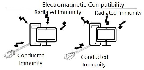
Figure 5. Electromagnetic Compatibility
EMC has become an important criterion for product quality. Electromagnetic compatibility (EMC) is divided into electromagnetic interference (EMI) and electromagnetic susceptibility (EMS).
Since automotive relays use a unified power supply, a high voltage will be formed when the relay coil is disconnected, which will interfere with other systems and modules. Therefore, plug-in automotive relays usually have parallel resistors or diodes for transient suppression to make the coil counter EMF less than 100V.
When the relay contacts are opened, an electric arc is generated and electromagnetic waves are emitted, which will affect the operation of the IC. If this happens, an arc extinguishing circuit can be added to the contact. You can also increase the distance between the relay and the IC.
 UTMEL
UTMEL
We are the professional distributor of electronic components, providing a large variety of products to save you a lot of time, effort, and cost with our efficient self-customized service. careful order preparation fast delivery service
1.What is the purpose of an automotive relay?
Relays are switches controlled by electrical power, like another switch, computer, or control module. The purpose of an automotive relay is to automate this power to switch electrical circuits on and off at particular times.
2.What are the different types of relays?
DC vs AC Relays.
Attraction Type Electromagnetic Relays.
Induction Type Relays. ...
Magnetic Latching Relays. ...
Change Over Relays.
Normally Open Relays.
Flasher Relays.
Electro-Mechanical Flasher.
3.How do automotive relays work?
Although there are various relay designs, the ones most commonly found in low voltage auto and marine applications are electro-mechanical relays that work by activating an electromagnet to pull a set of contacts to make or break a circuit. These are used extensively throughout vehicle electrical systems.
4.Why use a relay instead of a switch?
Relays are often used in circuits to reduce the current that flows through the primary control switch. A relatively low amperage switch, timer, or sensor can be used to turn a much higher capacity relay on and off. Another primary use for relays is when upgrading to halogen headlights on an older car.
5.Where are relays used?
Relays are used wherever it is necessary to control a high power or high voltage circuit with a low power circuit, especially when galvanic isolation is desirable.
 What is Time Delay Relay?UTMEL18 December 202515675
Hello everyone, I am Rose. Today I will introduce Time Relay to you. A Time Relay is an electrical component that is used on a circuit with a lower voltage or lower current to turn on or off a circuit with a higher voltage and bigger current or to regulate a higher voltage or larger power. This article will introduce some basic knowledge of Time Relay.
Read More What is Safety Relay?UTMEL12 April 202525510
Safety relays represent a critical advancement in industrial automation technology, serving as essential components in machine safety systems. Unlike standard relays, safety relays are specifically engineered to provide reliable protection in potentially hazardous environments. This article explores the fundamental aspects of safety relays, including their operational principles, wiring configurations, and proper implementation methods in industrial settings.
Read More What is Relay?UTMEL15 November 20217594
Hello everyone, I am Rose. Welcome back to the new post today. Relay is an autonomous electrical appliance used in electric drive systems for control, protection, and signal conversion. It is suitable for remote connection and disconnection of AC and DC small-capacity control circuits.
Read More AC Contactor: What is Self-Locking?UTMEL01 March 202212219
AC contactors often use three arc extinguishing methods: double-break electric arc extinguishing, longitudinal seam arc extinguishing and grid arc extinguishing. It is used to eliminate the arc generated by the moving and static contacts during the opening and closing process.This article mainly introduce the principle of AC Contactor self-locking.
Read More Weak Current Control Strong Current: How to use the Relay?UTMEL28 November 20226388
Hello everyone, I am Rose. Welcome to the new post today. Today I will introduce relay to you. Including its definition, parameters, working principle and so on.
Read More
Subscribe to Utmel !
![RC0805FR-073K9L]() RC0805FR-073K9L
RC0805FR-073K9LYageo
![ERA-3AEB2492V]() ERA-3AEB2492V
ERA-3AEB2492VPanasonic Electronic Components
![RC0805FR-076K04L]() RC0805FR-076K04L
RC0805FR-076K04LYageo
![ERJ-6ENF1004V]() ERJ-6ENF1004V
ERJ-6ENF1004VPanasonic Electronic Components
![AGQ200A03]() AGQ200A03
AGQ200A03Panasonic Electric Works
![WSL1206R1000FEA18]() WSL1206R1000FEA18
WSL1206R1000FEA18Vishay Dale
![CRCW2512499KFKEG]() CRCW2512499KFKEG
CRCW2512499KFKEGVishay Dale
![RC0805FR-0749R9L]() RC0805FR-0749R9L
RC0805FR-0749R9LYageo
![CRCW040247K0FKED]() CRCW040247K0FKED
CRCW040247K0FKEDVishay Dale
![WSL1206R0500FEA]() WSL1206R0500FEA
WSL1206R0500FEAVishay Dale


