

 Product
 Brand
Brand Articles
 Tools
Tools
ATmega2560 Design Guide: High-Pin Count 8-bit Microcontrollers

TxRx + MCU 769MHz~935MHz 1.8V~3.6V SPI 1Mbps 8.7mA~9.2mA - Receiving 13mA~25mA - Transmitting DSSS, BPSK, O-QPSK 256kB Flash 4kB EEPROM 8kB RAM 86 100-TFBGA


TxRx + MCU 769MHz~935MHz 1.8V~3.6V SPI 1Mbps 8.7mA~9.2mA - Receiving 13mA~25mA - Transmitting DSSS, BPSK, O-QPSK 256kB Flash 4kB EEPROM 8kB RAM 86 100-TFBGA
Integrate the ATmega2560 effectively. Analyzes 86 I/O architecture, 256KB Flash, PCB layout tips, and migration from Arduino to industrial hardware.
- Quick answer
- What is the ATmega2560?
- ATmega2560 chip vs. Arduino Mega 2560 board
- ATmega2560 specifications
- Architecture and peripherals
- ATmega2560 pinout and power pins
- Packages and ordering codes
- Design and integration guidelines
- Applications and limitations
- Alternatives and migration checks
- FAQ
- Official sources
- Specifications
- Datasheet PDF
Quick answer
The ATmega2560 is a 100-pin, 8-bit AVR microcontroller with 256 KB of self-programmable Flash, 8 KB of SRAM, 4 KB of EEPROM, 86 programmable I/O lines, four USARTs, one SPI interface, one two-wire serial interface, and a 16-channel 10-bit ADC. Microchip currently lists the device as In Production.
The chip is not the same product as an Arduino Mega 2560 board. The board uses an ATmega2560 but exposes a smaller set of connections and adds power, USB-to-serial, clock, reset, and connector circuitry. For a custom design, select the complete ATmega2560 ordering code, follow its voltage-versus-frequency limit, and verify the 100-pin package drawing and pin map in the current Microchip datasheet.
What is the ATmega2560?
The ATmega2560 belongs to Microchip's megaAVR family. It combines an 8-bit AVR CPU with on-chip program memory, data memory, nonvolatile EEPROM, timers, serial interfaces, analog conversion, interrupt logic, watchdog functions, and in-system programming. The device can execute many instructions in one clock cycle and is specified for throughput up to 16 MIPS at 16 MHz.
Its main advantage is not raw compute performance. It is the combination of a familiar 8-bit architecture, a large pin count, four hardware serial channels, 5 V operation on the 16 MHz grade, and enough Flash for larger control firmware. That makes it useful where deterministic control and many direct connections matter more than high-speed signal processing, wireless connectivity, or large RAM.
The 256 KB Flash does not mean the device has 256 KB of general-purpose RAM. Variables, stacks, buffers, and heaps use the much smaller 8 KB internal SRAM. Firmware that stores large strings, display buffers, or communication queues must manage SRAM deliberately.
ATmega2560 chip vs. Arduino Mega 2560 board
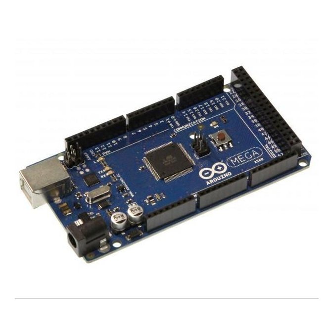
The ATmega2560 is the microcontroller IC. The Arduino Mega 2560 is a development board built around that IC. Arduino's official board page lists 54 digital I/O pins, 16 analog inputs, 15 PWM outputs, and four hardware serial ports. The bare 100-pin microcontroller has 86 programmable I/O lines, but not every chip pin is routed to an Arduino header.
The board also adds a 16 MHz clock, USB interface circuitry, voltage regulation, connectors, protection components, and a bootloader-oriented programming workflow. The ATmega2560 itself does not contain a native USB peripheral. Arduino Mega 2560 Rev3 uses a separate ATmega16U2 for USB-to-serial communication.
ATmega2560 specifications
The following summary is based on Microchip datasheet DS40002211A. Voltage and maximum clock frequency depend on the exact speed grade, so the generic 1.8 V to 5.5 V family range must not be applied unconditionally to every ordering code.
| Parameter | ATmega2560 value | Design note |
|---|---|---|
| CPU | 8-bit AVR enhanced RISC architecture | Up to 16 MIPS at 16 MHz under the applicable speed-grade conditions. |
| Program Flash | 256 KB | Includes configurable application and boot sections; available application space depends on the bootloader configuration. |
| Internal SRAM | 8 KB | This is the main constraint for large buffers, strings, and deeply nested code. |
| EEPROM | 4 KB | Suitable for nonvolatile settings and calibration data within endurance limits. |
| Programmable I/O | 86 lines | This is the chip-level count, not the Arduino header count. |
| ADC | 16 channels, 10-bit resolution | Analog performance depends on reference, source impedance, layout, filtering, and noise. |
| Serial interfaces | 4 USARTs, SPI, and byte-oriented two-wire interface | The two-wire interface is commonly used with I2C-compatible devices. |
| Timers | 6 Timer/Counters | Includes compare and PWM functions; map required outputs to the correct port pins. |
| Debug and programming | JTAG, ISP, and self-programming support | Confirm fuse settings and connector access before production. |
| Packages | 100-lead TQFP or 100-ball CBGA | Package suffix changes the footprint and assembly process. |
| Temperature grade | Industrial, -40 deg C to 85 deg C in the listed ordering table | Check the complete ordering code and current product documentation. |
Architecture and peripherals
CPU and memory organization
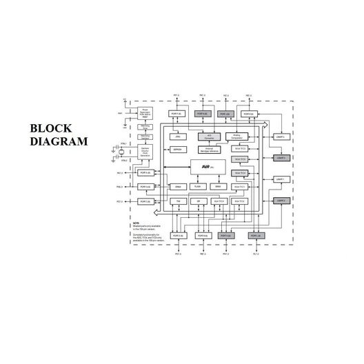
The AVR core uses 32 general-purpose 8-bit working registers and a Harvard-style separation between program and data memory. The Flash supports in-system self-programming and Read-While-Write operation between the application and boot sections. EEPROM provides nonvolatile data storage, while internal SRAM holds runtime data.
An external memory interface can connect SRAM, Flash, LCD controllers, or other parallel peripherals. Enabling that interface consumes dedicated address, data, and control pins, and external accesses take additional cycles. It is therefore a system-level expansion option, not a transparent substitute for internal SRAM.
Communication interfaces
Four programmable USARTs allow multiple independent serial links without relying entirely on software emulation. A design can, for example, allocate separate hardware channels to a host, a positioning receiver, a radio module, and a service port. SPI supports synchronous peripheral communication, while the two-wire interface supports bus-based sensors and control devices.
Interface availability alone does not establish electrical compatibility. Check logic levels, pull-ups, bus capacitance, peripheral voltage, clock rate, and pin multiplexing. A 5 V ATmega2560 output can damage a peripheral that is not 5 V tolerant.
Timers, PWM, ADC, and interrupts
The six Timer/Counters support timing, capture, compare, and PWM functions across multiple pins. The 16-channel 10-bit ADC can monitor several analog sources, but channel count does not guarantee accuracy. Reference stability, input impedance, switching noise, acquisition time, and PCB layout all affect conversion results.
ATmega2560 pinout and power pins
The ATmega2560 has ten main I/O ports identified as Ports A through L, with some letters omitted from the sequence used by smaller AVR devices. Most pins have an alternate peripheral function in addition to general-purpose digital I/O. Pin planning should start with required peripherals, clocks, programming access, analog inputs, and external-memory needs before assigning spare GPIO.
| Pin group | Main role | Important design check |
|---|---|---|
| VCC and GND | Digital supply and return | Connect every supply and ground pin; place local bypass capacitors close to the associated pins. |
| AVCC | Supply for Port F and the ADC | Connect AVCC to VCC even when the ADC is unused. When using the ADC, Microchip recommends a low-pass connection. |
| AREF | ADC reference input | Follow the selected reference mode and do not treat AREF as an ordinary GPIO. |
| RESET | Active-low reset input | Coordinate the pull-up, programming interface, external reset source, and noise environment. |
| XTAL1 and XTAL2 | External crystal or resonator connection | Use the oscillator configuration and load network specified for the chosen clock source. |
| USART, SPI, and two-wire pins | Hardware serial communication | Resolve alternate-function conflicts and voltage compatibility before routing. |
| JTAG pins | Boundary scan and on-chip debugging | JTAG fuse settings can affect whether shared port pins are available as GPIO. |
| External-memory pins | Multiplexed address/data and control bus | Enabling XMEM reassigns multiple port pins and changes timing requirements. |
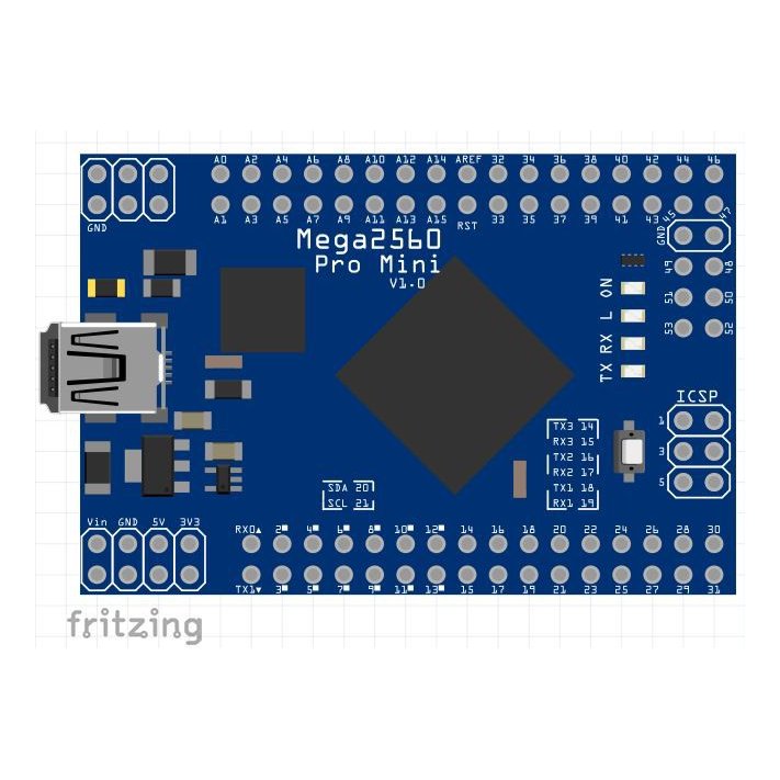
For PCB design, use the official TQFP or CBGA pin-configuration pages and package drawing. A development-board diagram cannot establish the bare chip pin numbers, hidden power pins, ball map, or land pattern.
Packages and ordering codes
The complete ordering code determines speed grade, package, and packing method. The datasheet lists the following core combinations for ATmega2560 devices:
| Example ordering code | Maximum speed | Supply range in ordering table | Package |
|---|---|---|---|
| ATmega2560V-8AU | 8 MHz | 1.8 V to 5.5 V | 100-lead TQFP |
| ATmega2560V-8CU | 8 MHz | 1.8 V to 5.5 V | 100-ball CBGA |
| ATmega2560-16AU | 16 MHz | 4.5 V to 5.5 V | 100-lead TQFP |
| ATmega2560-16CU | 16 MHz | 4.5 V to 5.5 V | 100-ball CBGA |
The additional R in codes such as ATmega2560-16AUR identifies tape-and-reel packing in the cited ordering table. It does not change the electrical architecture. Before purchasing, confirm that the exact suffix is currently orderable and that the package matches the approved footprint and assembly process.
Microchip's product page lists the ATmega2560 family as In Production. That family-level status does not guarantee stock, lead time, or availability for every suffix. Obtain current commercial information from Microchip or an authorized distributor, and keep the selected datasheet and errata revision with the BOM.
Design and integration guidelines
Match clock frequency to supply voltage
Do not combine the 1.8 V minimum and 16 MHz maximum as though they describe one unconditional operating point. The V-8 ordering codes are listed for up to 8 MHz from 1.8 V to 5.5 V, while the standard 16 MHz ATmega2560 codes are listed for 4.5 V to 5.5 V. Consult the speed-grade curves for any operating point outside the simple ordering-table summary.
Connect every supply domain correctly
Connect all VCC and GND pins and provide local high-frequency bypassing using a layout suited to the board stack-up and transient current paths. AVCC powers Port F and the ADC, so it must be connected even if analog conversion is disabled. When the ADC is used, route AVCC through an appropriate low-pass network and manage AREF according to the selected reference mode.
The official datasheet recommends a low-pass connection but does not make one fixed inductor and capacitor combination universally correct. Select components from the expected current, impedance, noise spectrum, and ADC performance target, then verify the result on the assembled PCB.
Plan around the 8 KB SRAM limit
Large global arrays, frame buffers, recursive code, dynamic allocation, and repeated string construction can exhaust 8 KB quickly. Store immutable tables and strings in program memory where practical, set explicit buffer limits, monitor stack headroom, and test worst-case protocol traffic. External SRAM is possible through XMEM, but it uses many pins and adds access cycles.
Keep programming and recovery access
Provide access to the selected programming and debug interface during prototype and production test. Record fuse settings, clock assumptions, brown-out configuration, bootloader size, and reset behavior. A device configured for an unavailable external clock can appear unresponsive even when the silicon is functional.
Add USB only when the system needs it
The ATmega2560 has USARTs but no native USB device peripheral. A custom board needs a separate USB-to-serial bridge or another USB-capable controller if USB is required. Arduino Mega 2560 Rev3 uses an ATmega16U2 for this function; other bridges require their own driver, clock, ESD, connector, and firmware considerations.
Applications and limitations
Where the ATmega2560 fits well
Control systems that need many direct GPIO connections.
Machines that need several independent UART channels.
5 V industrial or educational systems with moderate processing demand.
Data acquisition and automation nodes with multiple low-speed analog inputs.
Existing Arduino Mega or AVR firmware that benefits from a stable, familiar toolchain.
Microchip notes that the ATmega2560 has been widely used in 3D-printer controller platforms because of its high pin count and peripheral set. Suitability for a new design still depends on real-time load, memory use, motor-driver interfaces, safety requirements, and product lifetime.
Where another architecture may be a better fit
The ATmega2560 is less suitable when the application needs large RAM, high-rate digital signal processing, native USB, integrated Ethernet, Wi-Fi or Bluetooth, advanced security, or substantially higher CPU performance. In those cases, a 32-bit MCU or wireless SoC may reduce external components, but migration also changes voltage levels, peripherals, development tools, timing behavior, and software.
Alternatives and migration checks
No device should be approved for use on an existing ATmega2560 PCB from a family name or feature table alone. Start by deciding whether the project needs a maintenance change for an existing PCB or a new architecture for a redesigned product.
Same-family screening
The ATmega1280 shares the 100-pin ATmega family context and many peripheral concepts but has 128 KB of Flash rather than 256 KB. Even when two devices appear closely related, compare the complete package pin map, ordering code, memory map, fuse definitions, bootloader size, silicon errata, compiler target, and firmware image before qualification.
Architecture migration
Devices such as STM32 microcontrollers or ESP32 SoCs may offer more processing power or integrated connectivity, but they are not pin-compatible substitutes. Typical migration work includes a new PCB, 3.3 V level analysis, peripheral remapping, clock and power redesign, firmware porting, boot and debug changes, EMC retesting, and production-test updates.
Replacement warning: a candidate is acceptable only after electrical, timing, memory, package, firmware, qualification, lifecycle, and sourcing requirements have been checked against the actual application. A distributor cross-reference or development-board comparison is not proof of interchangeability.
FAQ
How many I/O pins does the ATmega2560 have?
The bare 100-pin ATmega2560 has 86 programmable I/O lines. The Arduino Mega 2560 board exposes 54 digital I/O pins and 16 analog inputs through its board connectors, so chip and board counts should not be mixed.
Can the ATmega2560 run at 16 MHz from 3.3 V?
The ATmega2560-16 ordering table specifies 16 MHz operation from 4.5 V to 5.5 V. Do not assume a 3.3 V, 16 MHz operating point is guaranteed. Select the correct speed grade and use the datasheet speed-grade curves.
Does the ATmega2560 have USB?
No. It has USART, SPI, and a two-wire serial interface, but no native USB peripheral. Development boards can add a separate USB interface controller or bridge.
What is the difference between ATmega2560-16AU and ATmega2560V-8AU?
Both are 100-lead TQFP devices in the cited ordering table. The -16AU code is the 16 MHz grade listed for 4.5 V to 5.5 V, while the V-8AU code is the 8 MHz grade listed for 1.8 V to 5.5 V.
Is ATmega2560 the same as Arduino Mega 2560?
No. The ATmega2560 is the microcontroller IC. Arduino Mega 2560 is a board that adds connectors, power circuitry, a clock, USB-to-serial hardware, and a software ecosystem around the chip.
Can ATmega1280 directly replace ATmega2560?
Do not assume a direct replacement. The ATmega1280 has less Flash and the exact package, pin map, fuses, bootloader, memory use, firmware target, and errata must be checked. Recompile and validate the complete product before approving any substitution.
Is the ATmega2560 still active?
Microchip currently marks the ATmega2560 product family as In Production. Confirm the status and availability of the exact ordering suffix at the time of purchase.
Official sources
Specifications
Datasheet PDF
- Datasheets :
- PCN Packaging :
- PCN Design/Specification :
- ConflictMineralStatement :
 TL072 OP-AMP: Where & How to Use TL072?
20 November 202125225
 NEMA17 Stepper Motor: Datasheet pdf, 1.5 A 1.8° Stepper Motor and Dimensions
29 November 202119429
 AD8033 80 MHz FastFET Op Amp: High-Speed Specs and Precision Performance Analysis
04 March 2026223
 1N4744A Zener Diodes: Circuit, Pinout, and Datasheet
08 November 20215169
 STMIPID02 vs Competitors: The Clear Choice
11 July 2025273
 Improving Device Performance with the MPM-30-12 Power Supply
27 May 2025165
 ESP12F: Ai-Thinker, Arduino, Pinout and Datasheet
09 March 20228832
 AD202 2000V Isolation Amplifier: Datasheet, Pinout, and Performance Deep Dive
03 March 2026451
 Google Unveils LM-Nav, A Robotic Navigation System, In Association With Universities
03 August 20225103
 Introduction to Sensors in the Internet of Things
24 September 20212565
 Unveiling the Potential of GaN Semiconductor-Enabled Three-Phase Propulsion Inverters for Enhanced EV Performance
09 August 20231726
 Introduction to Wireless Router
17 June 20214151
 Metaverse Is Coming, Who Will Lead Us to Touch the Real Virtual World?
04 May 2022886
 General PCB Layout Design Guidelines for RF and Digital-to-Analog Circuits
20 January 202214860
 An Overview of 12 Important CPU Specs
18 December 202112940
 Core Components behind Smart Glasses
28 June 202311627
Microchip Technology
In Stock
United States
China
Canada
Japan
Russia
Germany
United Kingdom
Singapore
Italy
Hong Kong(China)
Taiwan(China)
France
Korea
Mexico
Netherlands
Malaysia
Austria
Spain
Switzerland
Poland
Thailand
Vietnam
India
United Arab Emirates
Afghanistan
Åland Islands
Albania
Algeria
American Samoa
Andorra
Angola
Anguilla
Antigua & Barbuda
Argentina
Armenia
Aruba
Australia
Azerbaijan
Bahamas
Bahrain
Bangladesh
Barbados
Belarus
Belgium
Belize
Benin
Bermuda
Bhutan
Bolivia
Bonaire, Sint Eustatius and Saba
Bosnia & Herzegovina
Botswana
Brazil
British Indian Ocean Territory
British Virgin Islands
Brunei
Bulgaria
Burkina Faso
Burundi
Cabo Verde
Cambodia
Cameroon
Cayman Islands
Central African Republic
Chad
Chile
Christmas Island
Cocos (Keeling) Islands
Colombia
Comoros
Congo
Congo (DRC)
Cook Islands
Costa Rica
Côte d’Ivoire
Croatia
Cuba
Curaçao
Cyprus
Czechia
Denmark
Djibouti
Dominica
Dominican Republic
Ecuador
Egypt
El Salvador
Equatorial Guinea
Eritrea
Estonia
Eswatini
Ethiopia
Falkland Islands
Faroe Islands
Fiji
Finland
French Guiana
French Polynesia
Gabon
Gambia
Georgia
Ghana
Gibraltar
Greece
Greenland
Grenada
Guadeloupe
Guam
Guatemala
Guernsey
Guinea
Guinea-Bissau
Guyana
Haiti
Honduras
Hungary
Iceland
Indonesia
Iran
Iraq
Ireland
Isle of Man
Israel
Jamaica
Jersey
Jordan
Kazakhstan
Kenya
Kiribati
Kosovo
Kuwait
Kyrgyzstan
Laos
Latvia
Lebanon
Lesotho
Liberia
Libya
Liechtenstein
Lithuania
Luxembourg
Macao(China)
Madagascar
Malawi
Maldives
Mali
Malta
Marshall Islands
Martinique
Mauritania
Mauritius
Mayotte
Micronesia
Moldova
Monaco
Mongolia
Montenegro
Montserrat
Morocco
Mozambique
Myanmar
Namibia
Nauru
Nepal
New Caledonia
New Zealand
Nicaragua
Niger
Nigeria
Niue
Norfolk Island
North Korea
North Macedonia
Northern Mariana Islands
Norway
Oman
Pakistan
Palau
Palestinian Authority
Panama
Papua New Guinea
Paraguay
Peru
Philippines
Pitcairn Islands
Portugal
Puerto Rico
Qatar
Réunion
Romania
Rwanda
Samoa
San Marino
São Tomé & Príncipe
Saudi Arabia
Senegal
Serbia
Seychelles
Sierra Leone
Sint Maarten
Slovakia
Slovenia
Solomon Islands
Somalia
South Africa
South Sudan
Sri Lanka
St Helena, Ascension, Tristan da Cunha
St. Barthélemy
St. Kitts & Nevis
St. Lucia
St. Martin
St. Pierre & Miquelon
St. Vincent & Grenadines
Sudan
Suriname
Svalbard & Jan Mayen
Sweden
Syria
Tajikistan
Tanzania
Timor-Leste
Togo
Tokelau
Tonga
Trinidad & Tobago
Tunisia
Turkey
Turkmenistan
Turks & Caicos Islands
Tuvalu
U.S. Outlying Islands
U.S. Virgin Islands
Uganda
Ukraine
Uruguay
Uzbekistan
Vanuatu
Vatican City
Venezuela
Wallis & Futuna
Yemen
Zambia
Zimbabwe
![AT86RF233-ZU]() AT86RF233-ZU
AT86RF233-ZUMicrochip Technology
![ATMEGA256RFR2-ZU]() ATMEGA256RFR2-ZU
ATMEGA256RFR2-ZUMicrochip Technology
![AT86RF233-ZUR]() AT86RF233-ZUR
AT86RF233-ZURMicrochip Technology
![AT86RF231-ZU]() AT86RF231-ZU
AT86RF231-ZUMicrochip Technology
![MRF24J40-I/ML]() MRF24J40-I/ML
MRF24J40-I/MLMicrochip Technology
![ATMEGA256RFR2-ZUR]() ATMEGA256RFR2-ZUR
ATMEGA256RFR2-ZURMicrochip Technology
![ATSAMR21G18A-MU]() ATSAMR21G18A-MU
ATSAMR21G18A-MUMicrochip Technology
![AT86RF231-ZFR]() AT86RF231-ZFR
AT86RF231-ZFRMicrochip Technology
![AT86RF212B-ZUR]() AT86RF212B-ZUR
AT86RF212B-ZURMicrochip Technology
![AT86RF212B-ZU]() AT86RF212B-ZU
AT86RF212B-ZUMicrochip Technology


