
LM431 Shunt Regulator: Circuit, Pinout and Datasheet

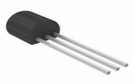
-40°C~85°C TA Adjustable 1.27mm PMIC LM431 TO-226-3, TO-92-3 (TO-226AA)
Unit Price: $0.341266
Ext Price: $0.34


-40°C~85°C TA Adjustable 1.27mm PMIC LM431 TO-226-3, TO-92-3 (TO-226AA)
LM431 is an adjustable precision zener shunt regulator. This article mainly introduce its circuit, pinout, datasheet and other detailed information about On Semiconductor LM431.

LM431 shunt regulator trimpot controlled power supply above set voltage indicator test circuit
LM431 Descirption
The LM431 is a three terminal adjustable shunt regulator.It is available in space-saving SOIC-8, SOT-23, and TO-92 packages. The main feature of this IC is a changeable output voltage, and the temperature strength is guaranteed over the entire temperature range of operation.The output voltage of this IC is may be ranged from the above 2.5V to 36V only by choosing two exterior resistors that perform like a voltage separated network. Due to the quickly activate characteristics, this IC is an outstanding alternative for several applications of zener diode. The similar components of this IC mainly include LM432, NJM2821, ZXRE060. NJM2822, NJM2820, This article discusses an introduction of IC LM 431.
LM431 Pinout

LM431 CAD Model
Footprint

LM431 Features
★Low-Output Noise
★Fast Turnon Response
★Programmable Output Voltage
★Low-Dynamic Output Impedance
★Average Temperature Coefficient 50 ppm/°C
★Available in Space-Saving SOIC-8, SOT-23, and TO92 packages
★Temperature Compensated for Operation Over the Full Temperature Range
Specifications
- TypeParameter
- Lifecycle Status
Lifecycle Status refers to the current stage of an electronic component in its product life cycle, indicating whether it is active, obsolete, or transitioning between these states. An active status means the component is in production and available for purchase. An obsolete status indicates that the component is no longer being manufactured or supported, and manufacturers typically provide a limited time frame for support. Understanding the lifecycle status is crucial for design engineers to ensure continuity and reliability in their projects.
ACTIVE (Last Updated: 1 day ago) - Factory Lead Time15 Weeks
- Mount
In electronic components, the term "Mount" typically refers to the method or process of physically attaching or fixing a component onto a circuit board or other electronic device. This can involve soldering, adhesive bonding, or other techniques to secure the component in place. The mounting process is crucial for ensuring proper electrical connections and mechanical stability within the electronic system. Different components may have specific mounting requirements based on their size, shape, and function, and manufacturers provide guidelines for proper mounting procedures to ensure optimal performance and reliability of the electronic device.
Through Hole - Mounting Type
The "Mounting Type" in electronic components refers to the method used to attach or connect a component to a circuit board or other substrate, such as through-hole, surface-mount, or panel mount.
Through Hole - Package / Case
refers to the protective housing that encases an electronic component, providing mechanical support, electrical connections, and thermal management.
TO-226-3, TO-92-3 (TO-226AA) - Number of Pins3
- Weight179mg
- Operating Temperature
The operating temperature is the range of ambient temperature within which a power supply, or any other electrical equipment, operate in. This ranges from a minimum operating temperature, to a peak or maximum operating temperature, outside which, the power supply may fail.
-40°C~85°C TA - Packaging
Semiconductor package is a carrier / shell used to contain and cover one or more semiconductor components or integrated circuits. The material of the shell can be metal, plastic, glass or ceramic.
Bulk - Published2012
- Tolerance
In electronic components, "tolerance" refers to the acceptable deviation or variation from the specified or ideal value of a particular parameter, such as resistance, capacitance, or voltage. It indicates the range within which the actual value of the component can fluctuate while still being considered acceptable for use in a circuit. Tolerance is typically expressed as a percentage or a specific value and is important for ensuring the accuracy and reliability of electronic devices. Components with tighter tolerances are more precise but may also be more expensive. It is crucial to consider tolerance when selecting components to ensure proper functionality and performance of the circuit.
±2% - JESD-609 Code
The "JESD-609 Code" in electronic components refers to a standardized marking code that indicates the lead-free solder composition and finish of electronic components for compliance with environmental regulations.
e3 - Pbfree Code
The "Pbfree Code" parameter in electronic components refers to the code or marking used to indicate that the component is lead-free. Lead (Pb) is a toxic substance that has been widely used in electronic components for many years, but due to environmental concerns, there has been a shift towards lead-free alternatives. The Pbfree Code helps manufacturers and users easily identify components that do not contain lead, ensuring compliance with regulations and promoting environmentally friendly practices. It is important to pay attention to the Pbfree Code when selecting electronic components to ensure they meet the necessary requirements for lead-free applications.
yes - Part Status
Parts can have many statuses as they progress through the configuration, analysis, review, and approval stages.
Active - Moisture Sensitivity Level (MSL)
Moisture Sensitivity Level (MSL) is a standardized rating that indicates the susceptibility of electronic components, particularly semiconductors, to moisture-induced damage during storage and the soldering process, defining the allowable exposure time to ambient conditions before they require special handling or baking to prevent failures
1 (Unlimited) - Number of Terminations3
- ECCN Code
An ECCN (Export Control Classification Number) is an alphanumeric code used by the U.S. Bureau of Industry and Security to identify and categorize electronic components and other dual-use items that may require an export license based on their technical characteristics and potential for military use.
EAR99 - Temperature Coefficient
The resistance-change factor per degree Celsius of temperature change is called the temperature coefficient of resistance. This factor is represented by the Greek lower-case letter “alpha” (α). A positive coefficient for a material means that its resistance increases with an increase in temperature.
50ppm/°C Typical - Terminal Finish
Terminal Finish refers to the surface treatment applied to the terminals or leads of electronic components to enhance their performance and longevity. It can improve solderability, corrosion resistance, and overall reliability of the connection in electronic assemblies. Common finishes include nickel, gold, and tin, each possessing distinct properties suitable for various applications. The choice of terminal finish can significantly impact the durability and effectiveness of electronic devices.
Tin (Sn) - Terminal Position
In electronic components, the term "Terminal Position" refers to the physical location of the connection points on the component where external electrical connections can be made. These connection points, known as terminals, are typically used to attach wires, leads, or other components to the main body of the electronic component. The terminal position is important for ensuring proper connectivity and functionality of the component within a circuit. It is often specified in technical datasheets or component specifications to help designers and engineers understand how to properly integrate the component into their circuit designs.
BOTTOM - Peak Reflow Temperature (Cel)
Peak Reflow Temperature (Cel) is a parameter that specifies the maximum temperature at which an electronic component can be exposed during the reflow soldering process. Reflow soldering is a common method used to attach electronic components to a circuit board. The Peak Reflow Temperature is crucial because it ensures that the component is not damaged or degraded during the soldering process. Exceeding the specified Peak Reflow Temperature can lead to issues such as component failure, reduced performance, or even permanent damage to the component. It is important for manufacturers and assemblers to adhere to the recommended Peak Reflow Temperature to ensure the reliability and functionality of the electronic components.
NOT SPECIFIED - Number of Functions1
- Terminal Pitch
The center distance from one pole to the next.
1.27mm - Time@Peak Reflow Temperature-Max (s)
Time@Peak Reflow Temperature-Max (s) refers to the maximum duration that an electronic component can be exposed to the peak reflow temperature during the soldering process, which is crucial for ensuring reliable solder joint formation without damaging the component.
NOT SPECIFIED - Base Part Number
The "Base Part Number" (BPN) in electronic components serves a similar purpose to the "Base Product Number." It refers to the primary identifier for a component that captures the essential characteristics shared by a group of similar components. The BPN provides a fundamental way to reference a family or series of components without specifying all the variations and specific details.
LM431 - Number of Outputs1
- Qualification Status
An indicator of formal certification of qualifications.
Not Qualified - Output Voltage
Output voltage is a crucial parameter in electronic components that refers to the voltage level produced by the component as a result of its operation. It represents the electrical potential difference between the output terminal of the component and a reference point, typically ground. The output voltage is a key factor in determining the performance and functionality of the component, as it dictates the level of voltage that will be delivered to the connected circuit or load. It is often specified in datasheets and technical specifications to ensure compatibility and proper functioning within a given system.
36V - Output Type
The "Output Type" parameter in electronic components refers to the type of signal or data that is produced by the component as an output. This parameter specifies the nature of the output signal, such as analog or digital, and can also include details about the voltage levels, current levels, frequency, and other characteristics of the output signal. Understanding the output type of a component is crucial for ensuring compatibility with other components in a circuit or system, as well as for determining how the output signal can be utilized or processed further. In summary, the output type parameter provides essential information about the nature of the signal that is generated by the electronic component as its output.
Adjustable - Max Output Current
The maximum current that can be supplied to the load.
100mA - Trim/Adjustable Output
Trim or adjustable output refers to the ability of an electronic component, such as a voltage regulator or power supply, to produce an output voltage that can be finely tuned or adjusted to meet specific requirements. This feature allows for precise control over the output voltage level, accommodating variations in load conditions or desired operational parameters. Users can typically achieve this adjustment through external resistors, potentiometers, or internal calibration mechanisms, ensuring optimal performance in diverse applications.
YES - Analog IC - Other Type
Analog IC - Other Type is a parameter used to categorize electronic components that are integrated circuits (ICs) designed for analog signal processing but do not fall into more specific subcategories such as amplifiers, comparators, or voltage regulators. These ICs may include specialized analog functions such as analog-to-digital converters (ADCs), digital-to-analog converters (DACs), voltage references, or signal conditioning circuits. They are typically used in various applications where precise analog signal processing is required, such as in audio equipment, instrumentation, communication systems, and industrial control systems. Manufacturers provide detailed specifications for these components to help engineers select the most suitable IC for their specific design requirements.
TWO TERMINAL VOLTAGE REFERENCE - Max Output Voltage
The maximum output voltage refers to the dynamic area beyond which the output is saturated in the positive or negative direction, and is limited according to the load resistance value.
36V - Max Input Voltage
Max Input Voltage refers to the maximum voltage level that an electronic component can safely handle without getting damaged. This parameter is crucial for ensuring the proper functioning and longevity of the component. Exceeding the specified maximum input voltage can lead to overheating, electrical breakdown, or permanent damage to the component. It is important to carefully adhere to the manufacturer's guidelines regarding the maximum input voltage to prevent any potential issues and maintain the reliability of the electronic device.
36V - Reference Type
a code object that is not stored directly where it is created, but that acts as a kind of pointer to a value stored elsewhere.
Shunt - Min Output Voltage
Min Output Voltage refers to the lowest voltage level that an electronic component, such as a voltage regulator or power supply, can provide reliably under specified conditions. It indicates the minimum threshold required for proper operation of connected devices. Operating below this voltage may lead to device malfunction or failure to operate as intended.
2.5V - Temp Coef of Voltage-Max
The parameter "Temp Coef of Voltage-Max" refers to the temperature coefficient of the maximum voltage rating of an electronic component. It indicates how the maximum voltage that the component can handle varies with temperature changes. A positive temperature coefficient means that the maximum voltage increases with temperature, while a negative coefficient indicates a decrease. This parameter is crucial for ensuring reliable performance and preventing breakdowns under different operating temperatures.
54.4 ppm/°C - Current - Cathode
Current - Cathode refers to the flow of electric current through the cathode terminal of an electronic component, such as a diode or a vacuum tube. It represents the amount of charge carriers, typically electrons, moving towards the cathode during operation. This parameter is crucial for determining the component's functionality and performance characteristics, as it influences the efficiency and stability of the circuit. High cathode current can indicate increased power consumption or potential overheating issues if not managed properly.
1mA - Height5.33mm
- Length5.2mm
- Width4.19mm
- RoHS Status
RoHS means “Restriction of Certain Hazardous Substances” in the “Hazardous Substances Directive” in electrical and electronic equipment.
ROHS3 Compliant - Lead Free
Lead Free is a term used to describe electronic components that do not contain lead as part of their composition. Lead is a toxic material that can have harmful effects on human health and the environment, so the electronics industry has been moving towards lead-free components to reduce these risks. Lead-free components are typically made using alternative materials such as silver, copper, and tin. Manufacturers must comply with regulations such as the Restriction of Hazardous Substances (RoHS) directive to ensure that their products are lead-free and environmentally friendly.
Lead Free
LM431 Functional Block Diagram

LM431 Equivalent Circuit

LM431 Layout Example

LM431 Alternatives

How to use LM431?
Before going for application circuit of LM431, let us first understand the internal working of the device and for that consider the functional diagram of the device as shown below.

In the LM431 functional diagram we have three main devices namely Op-amp, NPN transistor and +2.5V voltage source. Based on the working of the op-amp, the output voltage Vo/p will be positive only when Vref >+2.5V because voltage at inverting terminal of op-amp is +2.5V.
Now let us consider a simple application circuit for the device as shown below:

LM431 Applications
★Adjustable voltage and current linear as well as switching power supplies
★Monitor the voltage
★Current source and sink circuits
★Require precision references circuits
★Can replace zener diodes
LM331 Package

LM331 Manufacturer
ON Semiconductor is a semiconductor supplier company whose products include power and signal management, logic, discrete and custom devices for automotive, communications, computing, consumer, industrial, LED lighting, medical, military/aerospace, and power applications. ON Semiconductor operates a network of manufacturing facilities, sales offices, and design centers in North America, Europe, and Asia Pacific.
Trend Analysis
Datasheet PDF
- Datasheets :
- Environmental Information :
- PCN Design/Specification :
- PCN Packaging :
1.What directly replaces the LM431 three-terminal adjustable regulator?
It can be replaced with the following models: μA431, LM431, YL431, 5431, KA431, pPC431, YL431, S431.
A voltage stabilizer is a device that stabilizes the output voltage. The voltage stabilizer is composed of a constant voltage, a control circuit, and a servo motor.
When the input voltage or load changes, the control circuit will sample, compare, and amplify, and then drive the servo motor to rotate to change the position of the carbon brush of the voltage regulator, and automatically adjust the coil turns ratio to keep the output voltage stable.
2.Can tl431 replace LM431? Is there anything that needs to be changed on the circuit diagram?
Exactly the same, no changes are required.
3.What are common IC useful for electrical engineers to know?
Future is set around 3.3V. So keeping that in mind, one should know TL431 (LM431),LM1117–3.3,PC817
 AV101KE Through Hole Resistor: Datasheet, Application, Features
30 July 2021926
 OP270 Dual Op-Amp: Pinout, Equivalent and Datasheet
26 November 20213974
 10M02SCU169C8G: Key advantages, Datasheet, Features and Configuration
07 January 2022896
![39-01-2040 Receptacle Housing Dual Row 4 Circuits [FAQ]:Datasheet, Applications, and Technical Data](https://res.utmel.com/Images/Article/cbccf151-74f5-443a-a951-343628aa422c.jpg) 39-01-2040 Receptacle Housing Dual Row 4 Circuits [FAQ]:Datasheet, Applications, and Technical Data
39-01-2040 Receptacle Housing Dual Row 4 Circuits [FAQ]:Datasheet, Applications, and Technical Data22 March 2022764
 MPSA42 NPN Transistor: Pinout, Datasheet and Replacement
12 October 202112505
 INA115BU Instrumentation Amplifier:Datasheet, Application, Circuit
17 September 20211497
 Exploring the MCF51QU128 Microcontroller: Features, Specifications, and Applications
29 February 2024135
![ATTINY84A-PU AVR series Microcontroller IC 8-Bit 20MHz[FAQ]: Datasheet, Features, and Pinout](https://res.utmel.com/Images/Article/889533d0-63dd-4ec6-8d21-6b346255db18.jpg) ATTINY84A-PU AVR series Microcontroller IC 8-Bit 20MHz[FAQ]: Datasheet, Features, and Pinout
ATTINY84A-PU AVR series Microcontroller IC 8-Bit 20MHz[FAQ]: Datasheet, Features, and Pinout18 March 2022627
 What is First In First Out (FIFO)?
30 November 20213002
 What is a Digital Potentiometer?
08 January 20265949
 Introduction to FinFET
18 March 202126596
 A Selection of the Most Representative Charts——Artificial Intelligence Index Report
18 March 2022756
 Huawei Responded How to Solve the Problem of Chip Supply
29 March 20222695
 What is an Auto Transformer and Its Working?
01 April 20216901
 What is Chip: Definition, Classification and Design Process
17 January 20265266
 What is Conductivity Sensor?
20 June 202210991
ON Semiconductor
In Stock: 7044
Minimum: 1 Multiples: 1
Qty
Unit Price
Ext Price
1
$0.341266
$0.34
10
$0.321949
$3.22
100
$0.303726
$30.37
500
$0.286534
$143.27
1000
$0.270315
$270.32
Not the price you want? Send RFQ Now and we'll contact you ASAP.
Inquire for More Quantity
![TLV431BSN1T1G]() TLV431BSN1T1G
TLV431BSN1T1GON Semiconductor
![NCP431ACSNT1G]() NCP431ACSNT1G
NCP431ACSNT1GON Semiconductor
![TL431ACDR2G]() TL431ACDR2G
TL431ACDR2GON Semiconductor
![NCP51460SN33T1G]() NCP51460SN33T1G
NCP51460SN33T1GON Semiconductor
![KA431AZTA]() KA431AZTA
KA431AZTAON Semiconductor
![TLV431ASNT1G]() TLV431ASNT1G
TLV431ASNT1GON Semiconductor
![NCP432BVSNT1G]() NCP432BVSNT1G
NCP432BVSNT1GON Semiconductor
![TL431BVDR2G]() TL431BVDR2G
TL431BVDR2GON Semiconductor
![TL431IDR2G]() TL431IDR2G
TL431IDR2GON Semiconductor
![TL431AIDG]() TL431AIDG
TL431AIDGON Semiconductor


