

 Product
 Brand
Brand Articles
 Tools
Tools
Designing with ULN2004: Datasheet, Pinout, and Relay Driver Guide


PMIC 16 Pin SOP
Discover the ULN2004 Darlington Transistor Array datasheet. Learn why this high-voltage driver is ideal for 6V-15V CMOS logic, review pinouts, and verify stock availability today.
- Executive Summary: What is the ULN2004?
- 1. Technical Specifications & Performance Analysis
- 2. Pinout, Package, and Configuration
- 3. Design & Integration Guide (For Engineers & Makers)
- 4. Typical Applications & Use Cases
- 5. Alternatives and Cross-Reference Guide
- 6. Frequently Asked Questions (FAQ)
- 7. Datasheets & Resources
- Specifications
Executive Summary: What is the ULN2004?
The ULN2004 is a high-voltage, high-current Darlington transistor array specifically designed to interface 6V to 15V CMOS or PMOS logic families with inductive loads like relays and stepper motors. While often confused with similar drivers, its specific input resistance sets it apart for higher-voltage logic systems.
Market Position: A robust, legacy component widely used in industrial automation and HVAC control systems due to its high noise immunity compatibility.
Top Features: - 500 mA rated collector current per channel. - 50 V high-voltage output rating.
Integrated Suppression Diodes for driving inductive loads without external clamping.
Primary Audience: Industrial Design Engineers, HVAC Systems Integrators, and Procurement Managers seeking high-reliability drivers for 12V logic subsystems. - Supply Status: Active. Sourced from major manufacturers like Texas Instruments, STMicroelectronics, and Toshiba.
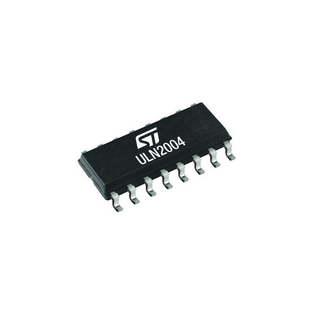
ULN2004 product photo
1. Technical Specifications & Performance Analysis
1.1 Core Architecture (Darlington Array)
The ULN2004 core consists of seven open-collector Darlington pairs with common emitters. This architecture allows the device to take relatively weak logic signals and amplify them to drive power-hungry components. Crucially, each channel includes an integral suppression diode for inductive load protection, eliminating the need for external flyback diodes on the BOM (Bill of Materials).
1.2 Key Electrical Characteristics
To ensure design feasibility, engineers must pay close attention to the input voltage requirements and current limitations:
Collector Current (Ic): Rated for 500 mA (Single Output). Note: Total package current is thermally limited.
Output Voltage (Vce): Supports up to 50 V, making it suitable for 24V and 48V industrial relays.
Input Voltage Range: Optimized for 6 V to 15 V logic levels.
Input Resistor: Includes a 10.5-kΩ series base resistor. This is the defining spec that separates it from the ULN2003 (which is for 5V TTL/CMOS).
1.3 Interfaces and Connectivity
The ULN2004 is designed to interface directly with:
CMOS Logic (6V to 15V)
PMOS Logic
Discrete High-Voltage Logic
It serves as the bridge between low-power logic controllers and high-power peripherals such as solenoids, DC motors, and LED displays.
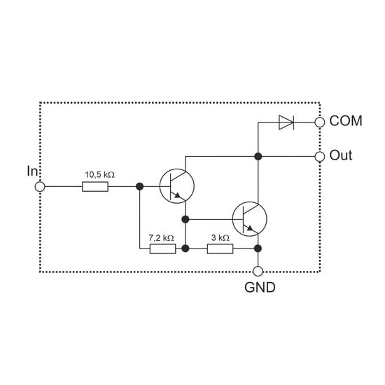
ULN2004 functional block diagram
2. Pinout, Package, and Configuration
2.1 Pin Configuration Guide
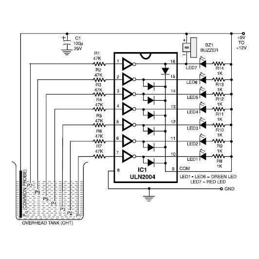
ULN2004 pinout diagram
The standard 16-pin DIP/SOIC layout is intuitive for layout engineers:
Pins 1-7 (Inputs): Connect to the MCU or Logic Gate outputs (6V-15V).
Pins 10-16 (Outputs): Open-collector outputs connecting to the load (Relay/Motor).
Pin 8 (GND): Common Emitter / System Ground.
Pin 9 (COM): Common Cathode for suppression diodes. Must be connected to the load supply voltage (e.g., +24V) to enable inductive kickback protection.
2.2 Naming Convention & Ordering Codes
Understanding the Part Numbers:The suffix dictates reliable sourcing for manufacturing lines:
A: Standard Series.
N: PDIP Package.
D: SOIC Package.
I: Industrial Temperature Range (often required for outdoor or automotive-adjacent designs).
Example:
ULN2004ADdenotes a Surface Mount device.
2.3 Available Packages
| Package Type | Dimensions | Common Use Case |
|---|---|---|
| ULN2004AN | PDIP-16 (Through-Hole) | Prototyping, Repair, Legacy Boards (Hand-solder friendly). |
| ULN2004AD | SOIC-16 (Surface Mount) | High-volume manufacturing, Compact PCBs. |
| ULN2004AIN | PDIP-16 | Industrial environments requiring wider temp ranges. |
3. Design & Integration Guide (For Engineers & Makers)
Pro Tip: Always verify your logic voltage source before selecting the ULN2004. If you are using a 3.3V or 5V MCU, this is likely the wrong part.
3.1 Hardware Implementation
Bypass Capacitors: While not strictly required for the array itself, placing a 0.1µF ceramic capacitor near the load supply layout prevents switching noise from affecting logic rails.
PCB Layout: Ensure the trace width for Pin 8 (GND) and Pin 9 (COM) is sufficient to handle the total returning current (sum of all active channels).
Thermal Management: The SOIC package has higher thermal resistance. If driving multiple channels at >200mA continuously, consider copper pours connected to GND pins for heat dissipation.
3.2 Common Design Challenges
Two major issues plague designs using the ULN2004. Address these during the schematic phase to avoid board spins.
1. The Logic Level Mismatch (Critical)Issue: Users often attempt to drive the ULN2004 with 3.3V (ESP32) or 5V (Arduino/TTL) logic.Analysis: The ULN2004 has a 10.5kΩ input resistor. At 5V, the base current is insufficient to fully saturate the Darlington pair for high-current loads, leading to overheating or failure to switch.Fix: Do not use ULN2004 for 5V/3.3V logic. Use the ULN2003A (2.7kΩ resistor) instead.
2. Thermal Dissipation OverloadIssue: The datasheet says "500mA per channel," so designers assume 7 channels x 500mA = 3.5A total.Analysis: This is impossible. The package power dissipation limits prevent all channels from running at maximum current simultaneously.Fix: Calculate total Power Dissipation (PD). If duty cycles are high, parallel channels to split current or reduce the number of active simultaneous loads.
4. Typical Applications & Use Cases
📺 Video Recommendation: ULN2004 Guide
4.1 Real-World Example: Industrial PLC Relay Card
In a Programmable Logic Controller (PLC) environment running on 12V or 15V internal logic, the ULN2004 is the standard driver. - Function: It converts the weak 12V logic signal from the control processor into a sinking current that energizes 24V mechanical cooling relays. - Protection: The internal clamp diodes on Pin 9 are tied to the +24V relay rail, safely shunting the high-voltage spike generated when the relay coil turns off.
5. Alternatives and Cross-Reference Guide
When sourcing becomes difficult or design requirements shift, consider these options.
Direct Replacements (Pin-Compatible)
These parts can usually swap directly onto a ULN2004 footprint:
STMicroelectronics ULN2004A
Toshiba ULN2004APG
ON Semiconductor ULN2004A
Functional Alternatives (Selection by Logic Voltage)
For 5V TTL/CMOS (Arduino/AVR): Use ULN2003A. It is pin-compatible but optimized for 5V logic.
For 14-25V PMOS: Use ULN2002A.
For Discrete MOSFETs: If higher current (>500mA) or faster switching is needed, replace the array with discrete N-channel MOSFETs, though this increases component count.
6. Frequently Asked Questions (FAQ)
Q: What is the difference between ULN2004 and ULN2003? A: The input base resistor value. ULN2004 has a 10.5kΩ resistor for 6-15V logic, while ULN2003 has a 2.7kΩ resistor for 5V TTL/CMOS logic.
Q: Can ULN2004 be used to drive LED strips? A: Yes, provided the LED strip is "Common Anode" (common positive voltage) and the total current per channel stays under 500mA.
Q: Is the ULN2004 suitable for battery-operated devices? A: It can be used, but Darlington pairs have a higher voltage drop (Vce(sat) ~1V-1.3V) compared to MOSFETs, making them less efficient for power-critical battery applications.
Q: Where can I find the datasheet and library files for ULN2004? A: Datasheets are available from Texas Instruments, ST, or ON Semi. Symbols are standard in most CAD tools like Altium, Eagle, and KiCad.
Q: How do I handle the "COM" pin if I am driving resistive loads like LEDs? A: For purely resistive loads, the COM pin is optional. However, connecting it to VCC is good practice to protect against any parasitic inductance in long wires.
7. Datasheets & Resources
Official Datasheet: Texas Instruments ULN2004A Datasheet
Development Tools: Breakout boards labeled "ULN2003 Module" can often be reworked with a ULN2004 chip for 12V logic prototyping.
Specifications
 LMV321 Rail-to-Rail Op Amp: Datasheet, Pinout and Applications
14 October 20212970
 STM32F072CBT6 Microcontroller: 40μA,48-LQFP, Pinout and Features
17 February 20222807
 2N5484 Transistor: 2N5484 Datasheet, Pinout, Equivalent
21 February 20223001
 Panasonic ERJ-6GEY0R00V 0-Ohm Resistor: 5 Key Applications in Modern Electronics
11 October 20251475
 AT24C32 Two-Wire Serial EEPROM: Datasheet, Pinout and Address
15 October 20215099
 MMBTA92 PNP High-Voltage Transistor: SOT-23, MMBTA92 Datasheet PDF
08 February 20222363
 LS404 2.5MHz Quad Op-Amp: Datasheet, Pinout, and Audio Performance Analysis
25 March 2026275
 74HCT00 Quad 2-input NAND Gate: Pinout, Features and Datasheet
10 November 20213338
 Analysis of Magnetic and Thermal Semiconductor Power Modules
13 March 20242269
 Sourcing for Embodied AI: How Large Action Models (LAMs) are Driving the Edge AI Chip Explosion
22 July 2026259
 Introduction to Types of Oscillator Circuits
14 January 202618000
 Introduction to 6 Common Power Supply Design Circuits
09 April 20226540
 Lithium-ion Battery: Structure, Working Principle and Package
08 November 202527004
 Enhancing Wi-Fi Security and Its Impacts on IoT Connectivity
25 October 20242757
 What is LCD? Working Principle, Features, and Future Trends
05 January 202614086
 The Comprehensive Guide to MOSFETs: Principles, Types, and Parameters (2026 Edition)
16 January 202620722
Texas Instruments
In Stock
United States
China
Canada
Japan
Russia
Germany
United Kingdom
Singapore
Italy
Hong Kong(China)
Taiwan(China)
France
Korea
Mexico
Netherlands
Malaysia
Austria
Spain
Switzerland
Poland
Thailand
Vietnam
India
United Arab Emirates
Afghanistan
Åland Islands
Albania
Algeria
American Samoa
Andorra
Angola
Anguilla
Antigua & Barbuda
Argentina
Armenia
Aruba
Australia
Azerbaijan
Bahamas
Bahrain
Bangladesh
Barbados
Belarus
Belgium
Belize
Benin
Bermuda
Bhutan
Bolivia
Bonaire, Sint Eustatius and Saba
Bosnia & Herzegovina
Botswana
Brazil
British Indian Ocean Territory
British Virgin Islands
Brunei
Bulgaria
Burkina Faso
Burundi
Cabo Verde
Cambodia
Cameroon
Cayman Islands
Central African Republic
Chad
Chile
Christmas Island
Cocos (Keeling) Islands
Colombia
Comoros
Congo
Congo (DRC)
Cook Islands
Costa Rica
Côte d’Ivoire
Croatia
Cuba
Curaçao
Cyprus
Czechia
Denmark
Djibouti
Dominica
Dominican Republic
Ecuador
Egypt
El Salvador
Equatorial Guinea
Eritrea
Estonia
Eswatini
Ethiopia
Falkland Islands
Faroe Islands
Fiji
Finland
French Guiana
French Polynesia
Gabon
Gambia
Georgia
Ghana
Gibraltar
Greece
Greenland
Grenada
Guadeloupe
Guam
Guatemala
Guernsey
Guinea
Guinea-Bissau
Guyana
Haiti
Honduras
Hungary
Iceland
Indonesia
Iran
Iraq
Ireland
Isle of Man
Israel
Jamaica
Jersey
Jordan
Kazakhstan
Kenya
Kiribati
Kosovo
Kuwait
Kyrgyzstan
Laos
Latvia
Lebanon
Lesotho
Liberia
Libya
Liechtenstein
Lithuania
Luxembourg
Macao(China)
Madagascar
Malawi
Maldives
Mali
Malta
Marshall Islands
Martinique
Mauritania
Mauritius
Mayotte
Micronesia
Moldova
Monaco
Mongolia
Montenegro
Montserrat
Morocco
Mozambique
Myanmar
Namibia
Nauru
Nepal
New Caledonia
New Zealand
Nicaragua
Niger
Nigeria
Niue
Norfolk Island
North Korea
North Macedonia
Northern Mariana Islands
Norway
Oman
Pakistan
Palau
Palestinian Authority
Panama
Papua New Guinea
Paraguay
Peru
Philippines
Pitcairn Islands
Portugal
Puerto Rico
Qatar
Réunion
Romania
Rwanda
Samoa
San Marino
São Tomé & Príncipe
Saudi Arabia
Senegal
Serbia
Seychelles
Sierra Leone
Sint Maarten
Slovakia
Slovenia
Solomon Islands
Somalia
South Africa
South Sudan
Sri Lanka
St Helena, Ascension, Tristan da Cunha
St. Barthélemy
St. Kitts & Nevis
St. Lucia
St. Martin
St. Pierre & Miquelon
St. Vincent & Grenadines
Sudan
Suriname
Svalbard & Jan Mayen
Sweden
Syria
Tajikistan
Tanzania
Timor-Leste
Togo
Tokelau
Tonga
Trinidad & Tobago
Tunisia
Turkey
Turkmenistan
Turks & Caicos Islands
Tuvalu
U.S. Outlying Islands
U.S. Virgin Islands
Uganda
Ukraine
Uruguay
Uzbekistan
Vanuatu
Vatican City
Venezuela
Wallis & Futuna
Yemen
Zambia
Zimbabwe
![TPS22913CYZVR]() TPS22913CYZVR
TPS22913CYZVRTexas Instruments
![TPS2052BDR]() TPS2052BDR
TPS2052BDRTexas Instruments
![TPS2051BDGNR]() TPS2051BDGNR
TPS2051BDGNRTexas Instruments
![TPS2044BD]() TPS2044BD
TPS2044BDTexas Instruments
![TPS2042BDR]() TPS2042BDR
TPS2042BDRTexas Instruments
![ULQ2003ADR]() ULQ2003ADR
ULQ2003ADRTexas Instruments
![TPS22945DCKR]() TPS22945DCKR
TPS22945DCKRTexas Instruments
![TPS2042BDGN]() TPS2042BDGN
TPS2042BDGNTexas Instruments
![TPS2557DRBT]() TPS2557DRBT
TPS2557DRBTTexas Instruments
![TPS2044BDR]() TPS2044BDR
TPS2044BDRTexas Instruments


