

 Product
 Brand
Brand Articles
 Tools
Tools
UC3842 vs UC3845: UVLO, Duty-Cycle Limits, and Startup Design

8 Terminals 8-Pin UC3845 DC to DC converter IC SWITCHING CONTROLLER 1 Outputs Transistor Driver


8 Terminals 8-Pin UC3845 DC to DC converter IC SWITCHING CONTROLLER 1 Outputs Transistor Driver
This engineering guide examines the silicon-level differences between UC3842 and UC3845 current-mode PWM controllers, highlighting UVLO thresholds, 50% duty-cycle limits, and frequency halving. It explains why direct component substitution causes startup hiccup or magnetic core saturation, provides mathematical formulas for sizing startup resistors and bias capacitors, and outlines a step-by-step bench diagnostic procedure for troubleshooting offline SMPS power supplies.
- Executive Engineering Verdict: The Drop-In Replacement Rule
- The Architectural Matrix: Deconstructing the UC384x Family
- Under-Voltage Lockout (UVLO): 16V Offline vs 8.4V DC-DC Operating Windows
- Maximum Duty Cycle and the Internal Toggle Flip-Flop: 100% vs 50%
- The Frequency Halving Dilemma and Magnetic Core Saturation (foscvsfsw)
- Why Replacing UC3842 with UC3845 Causes Startup Failure (The "Hiccup Trap")
- Startup Circuit Engineering: SizingRstart,CVCC, and the Auxiliary Handshake
- Slope Compensation and Peak Current-Mode Control Stability
- Bench Troubleshooting: Proving IC Failure Before Replacement
- Frequently Asked Questions (FAQ)
- Sources and references used for this guide
- Specifications
- Parts with Similar Specs
- Datasheet PDF
Executive Engineering Verdict: The Drop-In Replacement Rule
Never substitute a UC3845 directly into a UC3842 circuit, nor a UC3842 into a UC3845 circuit. Although both integrated circuits share an identical 8-pin DIP or SOIC pinout, identical error amplifier topology, and the same internal 5.0 V reference generator, their silicon operating architectures are incompatible.
Direct substitution fails across three hardware parameters:
Under-Voltage Lockout (UVLO) Thresholds: The UC3842 turns on at a typical threshold of 16.0 V and shuts down when bias voltage drops below 10.0 V, providing a 6.0 V operating hysteresis window. The UC3845 turns on at 8.4 V to 8.5 V and cuts off at 7.6 V to 7.9 V, providing a narrow hysteresis window of roughly 0.8 V.
Maximum Output Duty Cycle Clamp: The UC3842 allows the gate output to switch across duty cycles approaching 100% (practically limited to ~95%–97% by oscillator discharge dead-time). The UC3845 incorporates an internal toggle flip-flop that blanks alternate pulses, enforcing a hard hardware limit of[2] (measured bench maximum ~47%–48%).
Switching Frequency Division: The UC3842 switches at the same frequency as its internal timing oscillator (). The UC3845's toggle flip-flop divides the clock by two, causing the gate drive output to switch at half the oscillator frequency ().
Placing a UC3845 into an offline flyback power supply engineered around a UC3842 typically triggers one of two failures: perpetual startup hiccup mode (caused by auxiliary winding voltage starvation under duty-cycle clamping) or instantaneous primary MOSFET failure (caused by transformer core saturation when the switching frequency drops by half).
The Architectural Matrix: Deconstructing the UC384x Family
The classic 384x current-mode PWM controller family (originally introduced by Unitrode and standardized by Texas Instruments, STMicroelectronics, and ON Semiconductor) uses aarchitectural matrix. The four family members are partitioned by two parameters: UVLO threshold levels and maximum duty cycle capabilities.
| Parameter / Feature | UC3842 | UC3843 | UC3844 | UC3845 |
|---|---|---|---|---|
| Typical Turn-On Threshold () | 16.0 V (14.5 V – 17.5 V) | 8.4 V (7.8 V – 9.0 V) | 16.0 V (14.5 V – 17.5 V) | 8.4 V (7.8 V – 9.0 V) |
| Typical Turn-Off Threshold () | 10.0 V (8.5 V – 11.5 V) | 7.6 V (7.0 V – 8.2 V) | 10.0 V (8.5 V – 11.5 V) | 7.6 V (7.0 V – 8.2 V) |
| Operating Hysteresis () | 6.0 V | 0.8 V | 6.0 V | 0.8 V |
| Maximum Output Duty Cycle ( | 97% typ (approaches 100%) | 97% typ (approaches 100%) | 48% typ (clamped) | 48% typ (clamped) |
| Gate Drive Output Frequency () | ||||
| Internal Toggle Flip-Flop | Absent | Absent | Present | Present |
| Pre-Startup Current (max) | 1.0 mA (0.5 mA typ) | 1.0 mA (0.5 mA typ) | 1.0 mA (0.5 mA typ) | 1.0 mA (0.5 mA typ) |
| Operating Current (typ) | 11 mA to 17 mA | 11 mA to 17 mA | 11 mA to 17 mA | 11 mA to 17 mA |
| Target Power Topologies | Offline Flyback, Boost, SEPIC | DC-DC Boost, Low-voltage Flyback | Offline Forward, Two-Switch Flyback | Forward, Push-Pull, Half-Bridge DC-DC |
For circuit schematics and peripheral pin assignments, refer to the UC3842 PWM Controller Application Circuit & Datasheet[5] and the UC3845 Circuit, Pinout, and Technical Datasheet[6].
Topology Suitability Boundaries
UC3842: Optimized for single-ended offline AC-DC converters where the primary rectified bulk rail ranges fromto. At low AC line conditions, continuous conduction mode (CCM) and discontinuous conduction mode (DCM) flyback converters require duty cycles exceeding 50% to maintain secondary voltage regulation without driving peak currents beyond silicon limits.
UC3845: Optimized for forward converters, push-pull topologies, and DC-DC converters operating from dedicatedorindustrial bus rails. In these topologies, exceeding 50% duty cycle risks transformer core saturation due to incomplete flux reset.
Under-Voltage Lockout (UVLO): 16V Offline vs 8.4V DC-DC Operating Windows
The difference in UVLO turn-on and turn-off thresholds between the UC3842 and UC3845 reflects two distinct power-conversion operating environments: offline capacitor charging from rectified line voltage versus startup from low-voltage DC rails.
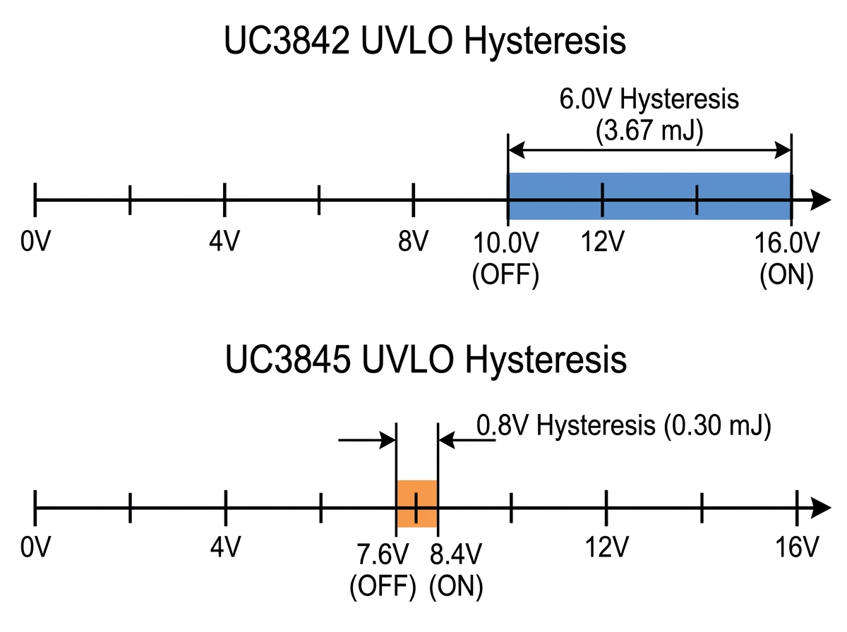
The Energy Reservoir Physics in Offline AC-DC Power Supplies
Offline power supplies typically power the controller IC during cold startup using a high-value bleeder resistor () connected to the rectified mains bulk capacitor (). Because the bleeder resistor drops hundreds of volts, its current throughput is constrained to 1 mA to 2 mA to limit steady-state power dissipation.
When the controller turns on, its current consumption surges from a quiescent pre-startup level of under 1.0 mA[1] to an active operating draw of 11 mA to 17 mA, plus the dynamic charge required to drive the external power MOSFET gate (). During this initial burst, the bleeder resistor cannot deliver the operating current. The controller relies entirely on energy stored inside the localbypass capacitor () until the transformer's auxiliary bootstrap winding develops sufficient rectified voltage to sustain the rail.
The usable electrical energy stored in the reservoir capacitor before the controller reaches UVLO shutdown is:
Evaluating a standardaluminum electrolytic reservoir capacitor on both ICs:
UC3842 Operating Window:
UC3845 Operating Window:
The UC3842 provides more than 12 times the startup energy buffer (vs.) of the UC3845 for the same capacitor value. In an offline circuit, the 0.8 V window of the UC3845 discharges in a few switching cycles, triggering UVLO cutoff long before the transformer can transfer energy to the secondary outputs and charge the auxiliary bias capacitor.
Gate Drive Integrity at Turn-On
Standard high-voltage power MOSFETs used in offline converters (rated) require gate-to-source voltages () between 10 V and 15 V to achieve full channel enhancement and minimize static on-state resistance ().
When the UC3842 turns on at 16.0 V, its totem-pole output driver delivers an initial gate drive pulse of approximately 14.5 V to 15.0 V (accounting for internal bipolar saturation drops), ensuring low conduction losses during peak inrush currents.
Conversely, the UC3845 turns on at 8.4 V to 8.5 V, delivering initial gate pulses of only 7.0 V to 7.5 V. Driving a standard high-voltage MOSFET at 7 V forces the channel into its linear (ohmic) region under heavy primary current loading, creating high conduction losses and risk of thermal failure.
Maximum Duty Cycle and the Internal Toggle Flip-Flop: 100% vs 50%
The second structural difference lies within the digital steering logic between the PWM latch and the output totem-pole driver stage.
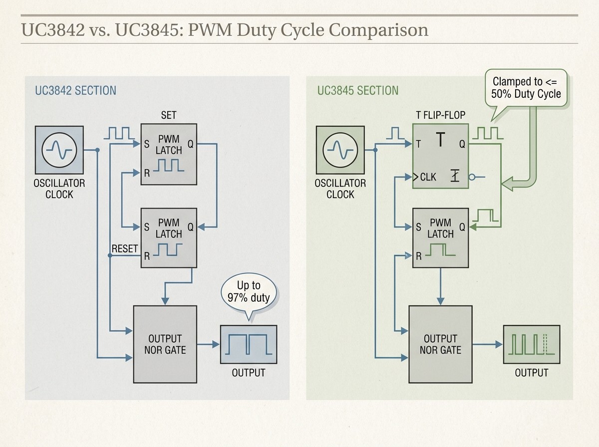
The Toggle Flip-Flop Mechanism
In the UC3842, the internal oscillator sets the PWM latch on its trailing edge, and the output (Pin 6) switches high. The output remains high until terminated by either the primary current-sense comparator (Pin 3 reaching the error amplifier threshold) or the oscillator's discharge blanking pulse. Because the driver triggers on every clock cycle, the duty cycle can approach 100%. The maximum attainable duty cycle is governed entirely by the timing capacitor () discharge duration:
For typical timing values (), dead-time is kept small, allowing practical duty cycles of 95% to 97%.
In the UC3844 and UC3845, an internal toggle (T-type) flip-flop is placed between the oscillator and the output steering logic. The flip-flop changes state on each clock cycle, blanking the gate driver on alternate cycles. Even if the feedback loop commands full output (COMP at Pin 1 pulled high), the output driver cannot conduct for more than half the total switching period. Bench measurements with Pin 2 grounded and Pin 1 pulled to the internal 5 V reference consistently confirm a hard ceiling of 47.5% to 48.5%.
Transformer Flux Balancing in Forward Topologies
This hardware clamping serves a protective role in forward converter topologies. Unlike flyback transformers (which function as coupled inductors storing energy during the switch-on time and transferring it during switch-off), forward transformers transfer energy directly to the output choke while the primary switch conducts.
During switch-off, the transformer's magnetizing inductance must fully demagnetize to prevent core saturation. Enforcing a 50% duty-cycle ceiling guarantees that at least half of every switching period is dedicated to core reset, preventing flux staircase accumulation and transformer failure.
The Frequency Halving Dilemma and Magnetic Core Saturation (vs)
The internal toggle flip-flop in the UC3845 alters the relationship between the timing network () at Pin 4 and the output switching frequency at Pin 6.
Oscillator vs. Switching Frequency Relationship
The timing network chargesvia the internal 5.0 V reference throughand discharges it through an internal constant-current sink. The internal oscillator frequency for the 384x family is calculated according to standard timing formulas[3] as:
For the UC3842: Gate drive output frequency equals the oscillator frequency:
For the UC3845: The toggle flip-flop divides the clock pulses by two:
When a circuit withandruns on a UC3842, the oscillator and the gate driver both switch at approximatelyto. Probing the same components with a UC3845 reveals an intactsawtooth ramp at Pin 4, but a gate drive square wave at Pin 6 operating at .
The Magnetic Core Saturation Hazard
Swapping a UC3842 with a UC3845 without modifying the timing resistor and capacitor introduces a major core saturation hazard.
Magnetic flux density swing () in a power transformer core is governed by Faraday's Law of Induction:
Where:
= Rectified DC bulk voltage across the primary winding
= Operating duty cycle
= Number of primary winding turns
= Core effective cross-sectional area ()
= Operating switching frequency ()
If a technician substitutes a UC3845 into a UC3842 circuit, the switching frequency () is cut in half while,, andremain unchanged. Halvingdoubles the magnetic flux swing () required for energy transfer.
Standard Manganese-Zinc (MnZn) power ferrite cores saturate at magnetic flux densities between and(3500 to 4000 Gauss) at. Most offline power supply transformers are engineered to operate at peak flux densities () betweenandunder full-load and low-line conditions, maintaining a safe margin below saturation.
Doubling the operating flux swing drives the ferrite core deep into magnetic saturation. When saturation occurs:
Primary magnetizing inductance collapses toward the air-core value ().
Primary current rises rapidly, exceeding the di/dt handling capacity of the controller.
The internal current-sense comparator propagation delay (~150 ns) becomes too slow to terminate the pulse before current exceeds the MOSFET's pulsed current rating ().
The primary MOSFET suffers instantaneous drain-to-source breakdown, often destroying the current-sense resistor and the PWM controller in the process.
Why Replacing UC3842 with UC3845 Causes Startup Failure (The "Hiccup Trap")
When an improper swap does not cause destructive saturation, the supply typically enters an endless cyclic restart sequence known as hiccup mode, accompanied by an audible ticking sound from the transformer.
{779} Comparison between UC3842, UC3843, UC3844, UC3845 ICs
The Step-by-Step Failure Sequence
Low-Threshold Premature Triggering: Mains voltage chargesthrough the high-value startup resistor. The UC3845 reaches its turn-on threshold atinstead of waiting for the design-intended. The controller wakes up with only a fraction of the capacitive energy required for startup.
Duty-Cycle Starvation During Inrush: When the converter starts, the secondary output filter capacitors are completely uncharged, acting as a momentary short circuit. In a flyback converter, transferring enough energy to build up secondary voltage quickly requires long duty cycles (). The UC3845's internal flip-flop clamps pulse widths to roughly 48%, starving secondary power delivery.
Auxiliary Rail Handover Failure: Because power transfer is restricted by duty-cycle clamping, the output voltages rise slowly. The transformer's auxiliary winding cannot produce sufficient flyback voltage to reverse-bias the bootstrap diode and support therail before the stored charge inis depleted.
Hysteresis Depletion and Cutoff: The controller consumes 11 mA to 17 mA while discharging. Because the hysteresis window is only 0.8 V (),drops belowwithin milliseconds. The UC3845 turns off, and switching stops.
Continuous Ticking Cycle: With switching halted, the IC reverts to its sub-milliampere standby state (). The startup resistor slowly rechargesfromback to. Onceis reached, the IC triggers again, discharges immediately, and shuts down, cycling indefinitely, a common pattern observed in bench repair troubleshooting[7].
Failure Modes by Swap Direction
| Substitution Direction | Resulting System Behavior | Root Failure Mechanism |
|---|---|---|
| UC3845 installed into UC3842 circuit | Endless startup cycling (audible ticking), zero or low secondary voltage, or primary MOSFET destruction. | 50% duty-cycle starvation prevents auxiliary handover; 0.8 V UVLO hysteresis depletes before auxiliary rail rises; 50% frequency halving risks transformer core saturation. |
| UC3842 installed into UC3845 circuit | Complete dead-circuit condition; zero gate switching activity; zero secondary voltage. | Circuit supply rail (typically regulated at) never reaches the UC3842's requiredturn-on threshold; controller remains locked in pre-startup standby mode indefinitely. |
Startup Circuit Engineering: Sizing,, and the Auxiliary Handshake
Designing a reliable startup circuit requires balancing pre-startup bleeder currents against reservoir capacitor holdup time and auxiliary winding reflections.
Sizing the Startup Resistor ()
The startup resistor must deliver enough current to cover the controller's pre-startup current draw () while maintaining margin under minimum DC input conditions:
Where:
= Minimum rectified DC bus voltage (typicallyfor anuniversal input line).
= Controller maximum turn-on threshold (for UC3842;for UC3845).
= Maximum pre-startup quiescent current ([4] across the UC384x series).
For reliable operation across component tolerances and ambient temperatures, engineers typically design for a bleeder current ofto.
To handle electrical stress, verify power dissipation and voltage withstand ratings under maximum line conditions (formains):
Standard SMD packaging (such as 0805 or 1206) cannot withstandcontinuous DC drops without dielectric breakdown. Offline startup strings should splitacross two or three resistors in series (for example, twometal-film resistors) to distribute voltage stress and heat dissipation.
Sizing the Bias Reservoir Capacitor ()
The reservoir capacitor () must provide power to the IC and drive the MOSFET gate during the startup interval (), without dropping below the turn-off threshold:
Where:
(typicallytototal).
= Time required for secondary outputs and auxiliary winding to reach steady-state conduction (typicallyto).
= Minimum hysteresis spread (worst-case for UC3842;worst-case tolerances for UC3845 require careful margin review).
Because aluminum electrolytic capacitors carry loose initial tolerances () and lose capacitance as their electrolyte dries at elevated temperatures, designers typically include an additionalsafety factor when calculatingfor long service life.
Slope Compensation and Peak Current-Mode Control Stability
Both the UC3842 and UC3845 use peak current-mode control, comparing a ramp signal proportional to primary inductor current against an error voltage. However, their differences in duty-cycle capability directly affect loop stability.
The Subharmonic Oscillation Criterion
In any peak current-mode switching regulator operating in continuous conduction mode (CCM), the current control loop becomes inherently unstable whenever the duty cycle exceeds 50% ().
When an external disturbance alters the inductor current by an incrementat the start of a switching period, that disturbance decays by the end of the cycle only if the down-slope of the inductor discharge current () is less than the up-slope of the charging current ():
If, then. The perturbation amplifies on every successive clock cycle, causing the PWM controller to alternate between wide and narrow output pulses. This open-loop phenomenon—known as subharmonic oscillation—produces audible transformer buzzing, irregular output ripple, and elevated switch stress.
Architectural Impact on Controller Selection
The UC3842 (Duty cycles up to 97%): When operating in CCM flyback or boost modes at low line voltages where duty cycle exceeds 50%, the UC3842 requires artificial slope compensation. This is implemented by taking an external emitter-follower transistor or resistor divider from the timing capacitor ramp (Pin 4) and summing a fractional voltage ramp into the current sense input (Pin 3). For optimal noise immunity, route Pin 3 using a dedicated Kelvin sense trace directly across the current-sense shunt resistor with a local low-pass RC filter placed adjacent to the IC pin, suppressing voltage spikes induced by PCB parasitic trace inductance. This added ramp increases the effective charging slope, ensuring stable operation at duty cycles up to 80%–90%.
The UC3845 (Duty cycle clamped to): Because its internal toggle flip-flop prevents the duty cycle from exceeding 50%, the operating conditioncannot occur. The UC3845 is naturally immune to subharmonic oscillation, removing the need for external slope compensation circuits in standard forward and push-pull applications.
Bench Troubleshooting: Proving IC Failure Before Replacement
When troubleshooting an inoperative or clicking power supply on the test bench, technicians often replace the PWM controller first. In practice, passive component degradation in the high-voltage startup and bias network causes the vast majority of offline SMPS startup failures.
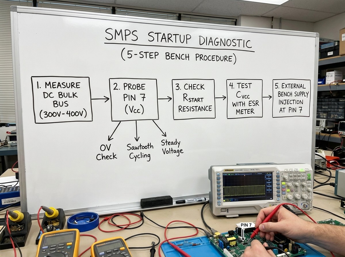
Follow this 5-step diagnostic procedure before removing the controller from the PCB:
Step 1: Measure the Rectified High-Voltage DC Bus
With the unit powered via an isolation transformer and series current-limiting bench bulb, measure the voltage across the main primary bulk capacitor (). A healthy offline bridge rectifier should measure approximately:
mains:
mains:
If this voltage is zero or measures below nominal, inspect the mains fuse, inrush NTC thermistor, and input rectifier diodes before working on the PWM control circuitry.
Step 2: Probe Controller Bias Voltage at Pin 7 ()
Connect an oscilloscope or multimeter across Pin 7 () and Pin 5 (GND) to identify the controller's operating state:
Case A: Voltage is clamped at 0 V to 2 V. The startup resistor string is open, thebypass capacitor has suffered dielectric breakdown, or the controller's internal zener protection clamp is shorted.
Case B: Voltage oscillates in a steady sawtooth pattern between 10.0 V and 16.0 V (for UC3842). The PWM controller is functional and its internal UVLO logic is cycling correctly. The failure typically stems from an overloaded secondary output, a shorted secondary rectifier diode, an open auxiliary bootstrap diode (), or a degradedcapacitor.
Case C: Voltage sits stable around 11 V to 14 V, but no switching pulses appear at Pin 6. The IC may be held in shutdown by a low-impedance path pulling Pin 1 (COMP) to ground or Pin 3 (ISENSE) above its 1.0 V threshold, or its internal reference generator has failed.
Step 3: Test High-Value Startup Bleeder Resistors ()
High-value carbon and metal-film resistors (to) running directly off high-voltage DC lines operate under constant thermal and electrical stress. Over extended service lives, these resistors frequently drift upward in value or fail open. Measure each resistor in the startup chain; a resistor that has drifted 20% to 50% above its nominal value can starve the controller of pre-startup current, preventing Pin 7 from ever reaching its turn-on threshold.
Step 4: Measure ESR and Capacitance of theBypass Capacitor
Electrolytic capacitors placed near primary heat sinks are prone to electrolyte evaporation over time. An ESR increase fromtoin acapacitor limits pulse current delivery during startup, triggering UVLO shutdown even when a multimeter shows the correct nominal DC voltage. Use an in-circuit ESR meter or replace the capacitor with a low-ESR,-rated unit to rule out bias instability.
Step 5: Test the IC with an External Bench Power Supply
To definitively test the controller without dealing with hazardous high-voltage DC rails:
Disconnect AC mains power and discharge all high-voltage capacitors.
Connect a current-limited DC bench power supply directly across Pin 7 () and Pin 5 (GND). Set the current limit to.
For a UC3842, ramp the power supply voltage up to. For a UC3845, ramp it up to.
Measure Pin 8 (). The internal bandgap reference must read (). If Pin 8 reads belowor matches, the IC's internal reference circuit is damaged.
Connect an oscilloscope probe to Pin 6 (OUTPUT). You should observe regular rectangular gate drive pulses matching the frequency set by the Pin 4 timing network.
Lower the supply voltage. Verify that gate switching halts cleanly whendrops pastfor the UC3842, orfor the UC3845.
Frequently Asked Questions (FAQ)
Can I replace a UC3842 with a UC3843 in an emergency?
Not directly in an offline AC-DC converter. While both the UC3842 and UC3843 allow duty cycles up to ~97%, the UC3843 uses low UVLO thresholds (on /off). In an offline mains circuit designed for 16 V turn-on, the UC3843 will wake up prematurely. Because the stored energy in the reservoir capacitor is too low at 8.4 V, the auxiliary bootstrap winding will fail to take over beforecollapses below 7.6 V, leaving the supply trapped in hiccup mode.
Can I replace a UC3842 with a UC3844?
No. The UC3844 shares the UC3842's 16.0 V turn-on and 10.0 V turn-off UVLO thresholds, but it incorporates the 50% duty-cycle toggle flip-flop. If installed in a single-switch flyback power supply that requires duty cycles over 50% during low mains voltage, the UC3844 will clip the pulse widths, causing output voltage collapse under load. Furthermore, its gate drive will switch at half the original frequency (), which risks driving the transformer core into saturation.
What is the pinout difference between the UC3842 and the UC3845?
There is no pinout difference. Both chips use an identical 8-pin package layout: Pin 1 (COMP), Pin 2 (VFB), Pin 3 (ISENSE), Pin 4 (RT/CT), Pin 5 (GND), Pin 6 (OUTPUT), Pin 7 (VCC), and Pin 8 (VREF). The differences are entirely internal—residing in the UVLO comparator reference dividers and the presence of the toggle flip-flop between the PWM latch and the output NOR gate.
Why do some datasheets list the UC3845 UVLO turn-on at 8.4 V and others at 8.5 V?
This minor difference reflects manufacturer-specific silicon revisions and test condition standards. Texas Instruments specifies the UC3845 turn-on threshold attypical (with an operating band ofminimum tomaximum). ON Semiconductor and STMicroelectronics commonly specify this threshold attypical. In bench practice, these variations fall within normal manufacturing tolerances and do not affect circuit behavior.
Sources and references used for this guide
UCx84x Current-Mode PWM Controllers datasheet (Rev. H)
Source type: official company documentation
Used for: Primary manufacturer electrical specifications, UVLO turn-on/turn-off thresholds, internal reference voltage tolerances, and pinout definitions.
Caution: Official manufacturer datasheet. Note slight typographical parameter differences between commercial (UC384x) and industrial (UC284x) temperature grades.APPLICATION NOTE UC3842/3/4/5 PROVIDES LOW-COST CURRENT-MODE CONTROL (SLUA143)
Source type: official company documentation
Used for: Authoritative engineering theory on internal toggle flip-flop operation, 50% maximum duty cycle clamping, and oscillator-to-output frequency halving.
Caution: Canonical Unitrode/TI engineering application note focused on architectural design theory.UC3842 Provides Low-Cost Current Mode Control (AN246)
Source type: official company documentation
Used for: Peak current-mode control loop dynamics, slope compensation circuit requirements for duty cycles exceeding 50%, and oscillator timing formulas.
Caution: STMicroelectronics vendor application note; represents ST-specific silicon implementation details.UC3842/UC3843/UC3844/UC3845 SMPS Controller Datasheet
Source type: official company documentation
Used for: Verification of multi-vendor parametric tolerances (Fairchild/ON Semiconductor), startup current limits, and propagation delay specifications.
Caution: Authorized distributor hosted datasheet for legacy Fairchild/ON Semiconductor product line.UC3842 PWM Controller Datasheet & Application Circuit
Source type: reputable professional source
Used for: Required internal contextual reference covering UC3842 pin configuration, basic application schematics, and peripheral decoupling.
Caution: Component distributor technical reference article; verify silicon parameters against Tier-1 manufacturer datasheets.UC3845 PWM Controller Circuit, Pinout, and Datasheet
Source type: reputable professional source
Used for: Required internal contextual reference covering UC3845 pinout mapping, package dimensions, and typical low-voltage DC-DC circuits.
Caution: Component distributor technical reference article; verify silicon parameters against Tier-1 manufacturer datasheets.Troubleshooting UC3845 and UC3842 SMPS Startup and Bias Issues
Source type: community discussion
Used for: Bench-level troubleshooting insights into auxiliary bootstrap winding collapse, high startup resistor drift, and electrolytic capacitor drying.
Caution: Community forum thread; used exclusively for understanding practical field failure symptoms and technician diagnostic pitfalls.
Specifications
Parts with Similar Specs
- ImagePart NumberManufacturerPackage / CaseNumber of PinsNumber of OutputsFactory Lead TimeMoisture Sensitivity Level (MSL)WidthLead FreeThicknessView Compare
![UC3845AD8]()
UC3845AD8
8-SOIC (0.154, 3.90mm Width)
8
1
6 Weeks
1 (Unlimited)
3.91 mm
Lead Free
1.58 mm
![UC3844D8]()
8-SOIC (0.154, 3.90mm Width)
8
1
6 Weeks
1 (Unlimited)
3.91 mm
Lead Free
1.58 mm
![TL2843BDR-8]()
8-SOIC (0.154, 3.90mm Width)
8
1
6 Weeks
1 (Unlimited)
3.91 mm
Lead Free
1.58 mm
![UC3843D8]()
8-SOIC (0.154, 3.90mm Width)
8
1
6 Weeks
1 (Unlimited)
3.91 mm
Lead Free
1.58 mm

Datasheet PDF
- Datasheets :
UC3845AD8-Texas-Instruments-datasheet-66618017.pdf
UC3845AD8-Texas-Instruments-datasheet-25361059.pdf
UC3845AD8-Texas-Instruments-datasheet-10283628.pdf
UC3845AD8-Texas-Instruments-datasheet-14164639.pdf
UC3845AD8-Texas-Instruments-datasheet-13030457.pdf
UC3845AD8-Texas-Instruments-datasheet-8619452.pdf
UC3845AD8-Texas-Instruments-datasheet-8202993.pdf
UC3845AD8-Texas-Instruments-datasheet-148588.pdf
- PCN Design/Specification :
 1N5408 Power Diode : Pinout, Price, Datasheet
27 July 202110433
 BR2325 23.0mm Lithium Poly-Carbon 3 V Battery: Datasheet, BR2325 VS CR2032, and Equivalents
30 March 20226735
 Texas Instruments MSP430G2x13 and MSP430G2x53: Ultra-Low-Power Mixed Signal Microcontrollers
29 February 2024185
 CD40106 HEX Inverter: Pinout, Applications and Datasheet
18 August 20217299
 M24C64-R I²C bus EEPROM: Pinout, Equivalent and Datasheet
23 March 20222479
 LM317K 1.2V TO 37V VOLTAGE REGULATOR:Pinout, Datasheet, and Applications
14 September 20213123
 TP4056:A LiPo battery charger IC
07 March 20224019
 OP07 Operational Amplifier: Pinout, Datasheet, OP07 VS LM308
15 December 202111408
 Revolutionizing Automotive Traction: A Comprehensive Review of Multiphase Drives for Next-Generation Vehicles
04 May 20234436
 Understanding UARTs: The Basics and Benefits of Serial Communication
06 March 20233208
 How to Design an Accurate DC Power Supply
15 October 20255745
 A Comprehensive Guide to FPGA Development Boards
07 September 202622922
 What is Variable Frequency Driver(VFD)?
20 October 20212965
 Reverse Voltage Protection for Battery Chargers
29 March 20226294
 Global Power Technology Authorized Distributor | UTMEL Electronics
21 November 20234387
 What is Safety Relay?
12 April 202526229
Texas Instruments
In Stock: 14
United States
China
Canada
Japan
Russia
Germany
United Kingdom
Singapore
Italy
Hong Kong(China)
Taiwan(China)
France
Korea
Mexico
Netherlands
Malaysia
Austria
Spain
Switzerland
Poland
Thailand
Vietnam
India
United Arab Emirates
Afghanistan
Åland Islands
Albania
Algeria
American Samoa
Andorra
Angola
Anguilla
Antigua & Barbuda
Argentina
Armenia
Aruba
Australia
Azerbaijan
Bahamas
Bahrain
Bangladesh
Barbados
Belarus
Belgium
Belize
Benin
Bermuda
Bhutan
Bolivia
Bonaire, Sint Eustatius and Saba
Bosnia & Herzegovina
Botswana
Brazil
British Indian Ocean Territory
British Virgin Islands
Brunei
Bulgaria
Burkina Faso
Burundi
Cabo Verde
Cambodia
Cameroon
Cayman Islands
Central African Republic
Chad
Chile
Christmas Island
Cocos (Keeling) Islands
Colombia
Comoros
Congo
Congo (DRC)
Cook Islands
Costa Rica
Côte d’Ivoire
Croatia
Cuba
Curaçao
Cyprus
Czechia
Denmark
Djibouti
Dominica
Dominican Republic
Ecuador
Egypt
El Salvador
Equatorial Guinea
Eritrea
Estonia
Eswatini
Ethiopia
Falkland Islands
Faroe Islands
Fiji
Finland
French Guiana
French Polynesia
Gabon
Gambia
Georgia
Ghana
Gibraltar
Greece
Greenland
Grenada
Guadeloupe
Guam
Guatemala
Guernsey
Guinea
Guinea-Bissau
Guyana
Haiti
Honduras
Hungary
Iceland
Indonesia
Iran
Iraq
Ireland
Isle of Man
Israel
Jamaica
Jersey
Jordan
Kazakhstan
Kenya
Kiribati
Kosovo
Kuwait
Kyrgyzstan
Laos
Latvia
Lebanon
Lesotho
Liberia
Libya
Liechtenstein
Lithuania
Luxembourg
Macao(China)
Madagascar
Malawi
Maldives
Mali
Malta
Marshall Islands
Martinique
Mauritania
Mauritius
Mayotte
Micronesia
Moldova
Monaco
Mongolia
Montenegro
Montserrat
Morocco
Mozambique
Myanmar
Namibia
Nauru
Nepal
New Caledonia
New Zealand
Nicaragua
Niger
Nigeria
Niue
Norfolk Island
North Korea
North Macedonia
Northern Mariana Islands
Norway
Oman
Pakistan
Palau
Palestinian Authority
Panama
Papua New Guinea
Paraguay
Peru
Philippines
Pitcairn Islands
Portugal
Puerto Rico
Qatar
Réunion
Romania
Rwanda
Samoa
San Marino
São Tomé & Príncipe
Saudi Arabia
Senegal
Serbia
Seychelles
Sierra Leone
Sint Maarten
Slovakia
Slovenia
Solomon Islands
Somalia
South Africa
South Sudan
Sri Lanka
St Helena, Ascension, Tristan da Cunha
St. Barthélemy
St. Kitts & Nevis
St. Lucia
St. Martin
St. Pierre & Miquelon
St. Vincent & Grenadines
Sudan
Suriname
Svalbard & Jan Mayen
Sweden
Syria
Tajikistan
Tanzania
Timor-Leste
Togo
Tokelau
Tonga
Trinidad & Tobago
Tunisia
Turkey
Turkmenistan
Turks & Caicos Islands
Tuvalu
U.S. Outlying Islands
U.S. Virgin Islands
Uganda
Ukraine
Uruguay
Uzbekistan
Vanuatu
Vatican City
Venezuela
Wallis & Futuna
Yemen
Zambia
Zimbabwe
![LM3485MM/NOPB]() LM3485MM/NOPB
LM3485MM/NOPBTexas Instruments
![LM3478MM/NOPB]() LM3478MM/NOPB
LM3478MM/NOPBTexas Instruments
![LM5085MY/NOPB]() LM5085MY/NOPB
LM5085MY/NOPBTexas Instruments
![UC2825DW]() UC2825DW
UC2825DWTexas Instruments
![UCC28950PWR]() UCC28950PWR
UCC28950PWRTexas Instruments
![LM3488MM/NOPB]() LM3488MM/NOPB
LM3488MM/NOPBTexas Instruments
![LM3150MHX/NOPB]() LM3150MHX/NOPB
LM3150MHX/NOPBTexas Instruments
![UCC28C43DR]() UCC28C43DR
UCC28C43DRTexas Instruments
![UCC25600DR]() UCC25600DR
UCC25600DRTexas Instruments


