

 Product
 Brand
Brand Articles
 Tools
Tools
RS-485 Port Protection Design Guide: TVS Selection, Surge Staging, and a Practical BOM


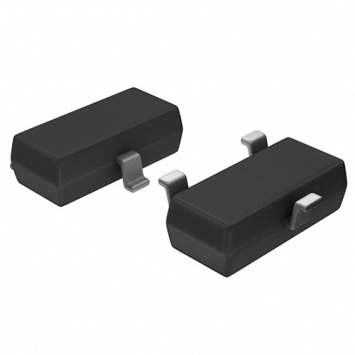
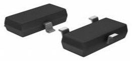
ESD Suppressor TVS 12V Automotive 3-Pin SOT-23 T/R
An RS-485 protection circuit has to preserve the bus's -7 V to +12 V common-mode operating window while surviving the transient tests that apply to the finished product. An asymmetrical 7 V/12 V TVS array is a strong starting point, but a TVS part number by itself does not establish an IEC 61000-4-5 system rating. The transceiver, coupling network, series impedance, surge-return path, PCB layout, and any coordinated primary stage all affect the result.
- 1. Start with the RS-485 common-mode window
- 2. ESD, EFT, and surge require different evidence
- 3. Compare SM712 parts using like-for-like parameters
- 4. Build the protection network around the target test
- 5. Ground and layout: design the current return, not just the schematic
- 6. Practical BOM by exposure level
- 7. Pre-compliance checklist
- 8. FAQ
- 9. References
- Related Utmel resources
- Specifications
- Parts with Similar Specs
- Datasheet PDF
An RS-485 protection circuit has to preserve the bus's -7 V to +12 V common-mode operating window while surviving the transient tests that apply to the finished product. An asymmetrical 7 V/12 V TVS array is a strong starting point, but a TVS part number by itself does not establish an IEC 61000-4-5 system rating. The transceiver, coupling network, series impedance, surge-return path, PCB layout, and any coordinated primary stage all affect the result.
1. Start with the RS-485 common-mode window
RS-485 receivers are designed to operate while the bus moves from -7 V to +12 V relative to the local signal reference. That wide and unequal window accommodates ground-potential differences between nodes. A protection device must avoid conducting during valid operation throughout that range.
A symmetrical bidirectional TVS has the same standoff voltage in both polarities. Choosing a symmetrical part with enough positive standoff may leave more negative clamping headroom than necessary; choosing a lower voltage can intrude into legitimate positive common-mode operation. A purpose-built asymmetrical array instead provides 7 V standoff in one direction and 12 V in the other.
For example, the Littelfuse SM712-02HTG specifies the following at 25 C:
| Parameter | Bus to reference | Reference to bus |
|---|---|---|
| Reverse standoff voltage | 12.0 V | 7.0 V |
| Breakdown voltage at 1 mA | 13.3 V | 7.5 V |
| Clamp voltage at 1 A, 8/20 us | 19 V | 11 V |
| Clamp voltage at 19 A, 8/20 us | 31 V | 19 V |
| Leakage at standoff voltage | 1 uA at 12 V | 20 uA at 7 V |
These are component-level test values, not allowable voltages at every RS-485 transceiver pin. The clamp voltage must still be checked against the protected transceiver's absolute maximum ratings under the current that the complete protection network permits.
On a multidrop bus, also include the protection-device capacitance and leakage in the loading analysis. A single 75 pF device may be modest, but cable capacitance and the protection at every node accumulate.
2. ESD, EFT, and surge require different evidence
The three common immunity tests represent different disturbances. A large ESD voltage number cannot be used as a substitute for an 8/20 us surge-current rating.
| Test | Typical disturbance | Relevant published evidence |
|---|---|---|
| IEC 61000-4-2 ESD | Human contact, connector handling | Contact and air discharge levels, dynamic clamp behavior, low-inductance layout |
| IEC 61000-4-4 EFT | Repetitive fast bursts from switching and relay activity | 5/50 ns current rating or a tested port-level result |
| IEC 61000-4-5 surge | Lightning-coupled and power-switching transients | 1.2/50 us voltage and 8/20 us current behavior in the complete coupling network |
Analog Devices notes that surge energy can be three to four orders of magnitude larger than ESD or EFT energy. That is why a part that survives impressive ESD levels may still need series current limiting or a coordinated primary protection stage for surge.
Component rating versus tested system level
The Littelfuse SM712 is rated for 19 A with an 8/20 us waveform. This does not mean that any board fitted with it passes a particular kilovolt level under IEC 61000-4-5. Test-generator source impedance, coupling resistors, line impedance, polarity, PCB return path, and the transceiver determine how current divides and what voltage reaches the IC.
The reverse mistake is also common: copying the kilovolt result from a reference design while changing its transceiver, blocking device, primary arrester, or layout. The result belongs to the tested assembly and conditions, not to one line item in its BOM.
3. Compare SM712 parts using like-for-like parameters
SM712 is used by multiple manufacturers, but a shared name and pin count do not make the parts automatically interchangeable. The table below includes only values stated on current first-party pages or datasheets reviewed for this update.
| Parameter | Littelfuse SM712-02HTG | Bourns CDSOT23-SM712 | Semtech SM712.TCT |
|---|---|---|---|
| Working window | -7 V / +12 V | -7 V / +12 V | -7 V / +12 V |
| Peak pulse power, 8/20 us | 600 W | 400 W | 400 W |
| Peak pulse current, 8/20 us | 19 A | 17 A | 12 A |
| IEC 61000-4-2 | +/-30 kV contact and air | +/-8 kV contact, +/-15 kV air minimum; up to +/-30 kV stated maximum | +/-8 kV contact, +/-15 kV air |
| IEC 61000-4-4, 5/50 ns | 50 A | Not stated in the cited datasheet | 40 A |
| Capacitance | 75 pF at 0 V, 1 MHz | 75 pF typical at 0 V, 1 MHz | Described as low capacitance; no numeric value on the cited product page |
| Operating temperature | -40 C to +125 C | -55 C to +150 C | Check the selected ordering-code datasheet |
| Qualification statement | AEC-Q101 | Not listed in the cited datasheet | Not listed on the cited product page |
This update corrects an important sourcing trap: Semtech's current official product page states 12 A for the 8/20 us lightning test, not 17 A. Distributor tables or inherited BOM notes should not override the manufacturer's current specification.
Clamping values also need their test current and polarity attached. Littelfuse states 31 V and 19 V at 19 A for the two directions. Bourns states 26 V and 14 V at 17 A. Those values describe different currents, so the lower number cannot be treated as a universal ranking without checking the protected IC and expected current.
Sourcing rule: put the manufacturer and complete ordering code on the approved BOM. If a second source is required, validate it in the same circuit and at the same environmental and immunity conditions. Package name, pin assignment, clamping curve, leakage, temperature range, qualification, and lifecycle all need independent confirmation.
What about Littelfuse SC712-02HTG?
Littelfuse published a revised SC712-02HTG datasheet in June 2026. It describes a 640 W asymmetrical -7 V/+12 V array rated for 20 A at 8/20 us, with a -40 C to +150 C operating range. Those figures justify evaluating it in a new design, but the cited document does not label it as a drop-in successor to SM712-02HTG. Treat it as a separate device until pinout, clamping, qualification, package, lifecycle, and system test results have been reviewed.
4. Build the protection network around the target test
There is no universal sequence of TVS, choke, resistor, TBU, GDT, and MOV that is correct for every port. Published designs use different coordination strategies. Select a topology for the actual environment, then keep the entire external-interface protection zone close to the connector and follow the validated current paths.

Baseline protection for controlled indoor installations
A baseline port commonly includes:
An asymmetrical 7 V/12 V TVS array located close to the connector.
A short, low-inductance shunt path to the protection reference chosen for the product architecture.
Transceiver supply decoupling located at the IC.
Correct termination and fail-safe biasing for the bus topology.
Tight A/B pair routing with minimal stubs through the connector-protection-transceiver path.
This is an appropriate starting point for ESD and moderate EFT design, but it does not establish a surge pass level. Analog Devices CN0313 is a useful example of the distinction: its TVS-only scheme is reported up to 8 kV contact and 15 kV air ESD, 2 kV EFT, and 1 kV surge under the documented test setup. Higher surge levels use additional coordinated components.
Add current limiting when the clamp exceeds the IC limit
Series impedance can limit the residual current that reaches the transceiver while the TVS is conducting. Analog Devices AN-960 discusses 10 ohm to 20 ohm series resistors for higher transients, and TI's TIDA-00731 uses pulse-proof resistors in a tested multistage circuit.
Choose the value from the transceiver input limits, signal amplitude, cable termination, required data rate, and pulse energy. Use pulse-withstanding parts where the surge test can deposit more energy than an ordinary small thick-film resistor is qualified to absorb.
Treat the common-mode choke as an EMC option, not a surge certificate
A common-mode choke can reduce common-mode noise and help with emissions or EFT susceptibility, but it is not mandatory in every successful IEC 61000-4-5 design. TI's TIDA-00731 high-surge reference design, for example, coordinates MOV, TBU, TVS, and pulse-proof resistance without using a choke as the defining surge element.
If a choke is added, verify common-mode impedance over the relevant frequency range, differential insertion loss at the intended data rate, saturation behavior, insulation requirements, and the effect of its placement on the surge-current path. The exact order should follow a simulated or tested circuit rather than a generic internet diagram.
Add a coordinated primary stage for exposed cables
Long outdoor runs and cables that leave the enclosure can justify a primary high-energy stage such as a MOV or gas-discharge tube, followed by a current-limiting or blocking element and a lower-voltage secondary TVS. Coordination matters because the faster secondary clamp can otherwise absorb the event before the primary device reaches its operating threshold.
Two first-party examples show why the whole network must remain intact:
| Published design | Protection network | Reported system result | Design-use caveat |
|---|---|---|---|
| TI TIDA-00731 with SN65HVD82 | MOV + TBU + CDSOT23-SM712 + pulse-proof resistance | +/-30 kV contact and air ESD, +/-4 kV EFT, +/-8 kV surge | The same protection with another transceiver produced lower contact-ESD and surge results; the result is assembly-specific |
| ADI AN-1161, scheme 3 | GDT + TBU + TVS | 6 kV surge in the documented test | Preserve the documented component coordination and revalidate the PCB implementation |
| ADI CN0313, TVS-only scheme | Asymmetrical TVS | 8 kV contact / 15 kV air ESD, 2 kV EFT, 1 kV surge | Useful baseline, not evidence for a higher surge level |
Galvanic isolation addresses ground-potential differences and breaks a conductive ground loop, but it does not remove the need to protect exposed bus pins. Integrated protected transceivers can reduce component count: for example, the ADM2795E datasheet states certified +/-4 kV surge, +/-2 kV EFT, and +/-8 kV contact / +/-15 kV air ESD for its documented configurations. Compare its isolation, supply, data-rate, and coupling requirements with the discrete approach before selecting it.
5. Ground and layout: design the current return, not just the schematic
The TVS should be close enough to the connector that the transient current is diverted before it travels across the logic area. Keep the line-side trace, TVS connection, and return loop short and wide enough for the pulse current. Route A and B together and avoid long branches to test points or unused footprints.
The correct return node is architecture-dependent. If the product has chassis or protective earth at the connector and the safety design permits it, a short path to that structure can keep surge current out of logic ground. A floating or isolated product may instead use an isolated local reference and a staged return network. Therefore, "always connect the TVS directly to chassis" is not a safe universal rule; the return path must agree with the product's insulation, safety, shield, and EMC plan.
Keep noisy switch nodes, isolated-power transformer fields, and high-current loops away from the differential pair. Review creepage and clearance around primary arresters and chassis connections, especially when the connector is user-accessible or the cable leaves the building.
6. Practical BOM by exposure level
| Function | Controlled indoor bus | Industrial cabinet | Exposed or outdoor run |
|---|---|---|---|
| Secondary clamp | 7 V/12 V asymmetrical TVS | Same, selected against transceiver limits | Same, coordinated with primary stage |
| Current limiting | Add if clamp current requires it | Pulse-rated series resistance or validated TBU network | Coordinated TBU/series impedance |
| Primary energy diversion | Usually not required | Application-dependent | MOV or GDT selected for the coupling and safety plan |
| Common-mode filtering | Optional after signal-integrity review | Optional for EMC objective | Optional; not a substitute for surge coordination |
| Isolation | Application-dependent | Recommended across separate ground domains | Strongly consider isolated transceiver and supply |
| Evidence required | Port-level ESD/EFT test | Complete IEC 61000-4-x test record | Complete test plus safety, thermal, and repeated-event review |
These columns are design starting points, not guaranteed compliance recipes. The final BOM must include manufacturer ordering codes, voltage and pulse ratings, resistor pulse curves, arrester tolerances, temperature range, PCB spacing, and the exact transceiver used during qualification.
7. Pre-compliance checklist
Confirm the valid bus common-mode window and the transceiver's absolute maximum bus-pin voltages.
Record TVS standoff, breakdown, and clamp voltage in both polarities with the test current and waveform.
Keep manufacturer and complete ordering code on every protection BOM line.
Place the external-interface protection zone at the connector and minimize the shunt loop inductance.
Define the surge-current return path for chassis, isolated, or non-chassis construction.
Calculate pulse energy in every series resistor and verify its pulse-withstanding curve.
Treat common-mode choke placement and impedance as a signal-integrity and EMC design decision.
Preserve the complete topology when adapting a published reference design.
Test both common-mode and differential-mode coupling where the product standard requires them.
Repeat communication checks during and after immunity tests; survival alone is not the only performance criterion.
Re-run the test when a TVS, transceiver, TBU, MOV, GDT, connector, grounding method, or PCB layout changes.
8. FAQ
Can a normal bidirectional TVS be used on RS-485?
It can be electrically evaluated, but its symmetrical standoff does not match the -7 V to +12 V operating window. A purpose-built asymmetrical array usually provides tighter protection without intruding into valid common-mode operation. Check both polarities against the transceiver and bus requirements.
Does an SM712 guarantee IEC 61000-4-5 compliance?
No. Its datasheet gives component pulse ratings. A port's surge level depends on the test generator, coupling network, current limiting, return path, transceiver, PCB layout, and any coordinated primary stage.
Are Littelfuse, Bourns, and Semtech SM712 parts interchangeable?
Not automatically. Their 8/20 us current ratings, ESD/EFT statements, temperature ranges, and published clamping data differ. Qualify each approved source in the finished protection circuit.
Must the TVS return connect to chassis ground?
Use a short, low-inductance path to the protection reference defined by the product architecture. Chassis or protective earth is often preferable when it exists and the safety design permits it, but isolated and non-chassis products require a different return strategy.
Is a common-mode choke required for surge protection?
No. It can help an EMC objective, but published high-surge designs also use coordinated MOV, GDT, TBU, TVS, and resistance without treating a choke as the surge-certifying element. Verify its placement and signal-integrity impact if used.
9. References
Littelfuse SM712-02HTG datasheet, revised August 22, 2019.
Bourns CDSOT23-SM712 datasheet, revised June 2024.
Semtech SM712 product page, accessed August 2026.
Littelfuse SC712-02HTG datasheet, revised June 16, 2026.
Texas Instruments TIDA-00731 design guide, IEC ESD, EFT, and surge RS-485 bus protection reference design.
Texas Instruments SLLA639, Simplifying Surge Protection for RS-485 Using Integrated Solutions.
Analog Devices AN-960, RS-485/RS-422 Circuit Implementation Guide.
Analog Devices AN-1161, RS-485/RS-422 EMC protection guidance.
Analog Devices CN0313, RS-485 EMC protection circuit note.
Analog Devices AN-1398, system-level EMC solution for isolated RS-485 interfaces.
Related Utmel resources
Specifications
Parts with Similar Specs
- ImagePart NumberManufacturerPolarityBreakdown VoltageClamping VoltagePeak Pulse PowerPeak Pulse CurrentRoHS StatusNumber of ChannelsHTS CodeView Compare
![SM712-02HTG]()
SM712-02HTG
UNIDIRECTIONAL
13.3 V
31 V
600 W
19 A
ROHS3 Compliant
2
8541.10.00.50
![CDSOT236-DSL0312]()
Bidirectional
26.7 V
50 V
500 W
10 A
ROHS3 Compliant
2
8541.10.00.50
![CDSOT236-DSL0324]()
Bidirectional
26.2 V
40 V
-
6 A
ROHS3 Compliant
2
8541.10.00.50
![SM24CANB-02HTG]()
Bidirectional
14 V
20 V
500 W
35 A
ROHS3 Compliant
2
8541.10.00.50
![CDSOT23-T24CAN]()
Bidirectional
26 V
40 V
500 W
15 A
ROHS3 Compliant
2
8541.10.00.50


Datasheet PDF
- Datasheets :
- Environmental Information :
.png) AD7524: A High-Performance Digital to Analog Converter for Data Acquisition
AD7524: A High-Performance Digital to Analog Converter for Data Acquisition06 March 2024187
 BC847B General Purpose SMD NPN Transistors:Brief Introduction
01 April 20223644
 MJE15030G NPN Transistor: Datasheet, Equivalent, and Pinout
28 August 20215180
 SX1276 Transceiver: Datasheet, SX1276 vs. SX1272
09 November 202117577
![SA15 TVS DIODE 15VWM 24.4VC DO15[FAQ]: Datasheet, Features, and Applications](https://res.utmel.com/Images/Article/842c249e-4640-4601-b47d-33a2290d80f7.jpg) SA15 TVS DIODE 15VWM 24.4VC DO15[FAQ]: Datasheet, Features, and Applications
SA15 TVS DIODE 15VWM 24.4VC DO15[FAQ]: Datasheet, Features, and Applications09 March 2022528
 TB6600HG-Stepper Motor Controllers / Drivers
28 February 20221907
 RS232 VS DB9: Disadvantages and advantages of RS232 and DB9, Differences between the RS232 and DB9
23 February 202223275
 BC817-40 NPN Transistor: Pinout, Equivalent and Datasheet
26 March 20226334
 Sourcing GaN Power Devices for AI Servers, EVs, and Industrial Applications
10 July 2026273
 What is Smoke Detector?
26 October 20213943
 AI and PCB in 2026: Why Circuit Boards Became a Hot Topic in the AI Hardware Race
01 July 20261832
 Laser diodes or LEDs what sets them apart
14 July 20252996
 Introduction to FinFET
18 March 202131059
 Random Access Memory: Definition, Types and Working
29 August 202010823
 BB5 Series MCU: Features, Applications and Comparison
19 November 20214589
 Strain Gauges: Structure, Working Principle and Common Types
16 December 202014236
Littelfuse Inc.
In Stock: 11004
United States
China
Canada
Japan
Russia
Germany
United Kingdom
Singapore
Italy
Hong Kong(China)
Taiwan(China)
France
Korea
Mexico
Netherlands
Malaysia
Austria
Spain
Switzerland
Poland
Thailand
Vietnam
India
United Arab Emirates
Afghanistan
Åland Islands
Albania
Algeria
American Samoa
Andorra
Angola
Anguilla
Antigua & Barbuda
Argentina
Armenia
Aruba
Australia
Azerbaijan
Bahamas
Bahrain
Bangladesh
Barbados
Belarus
Belgium
Belize
Benin
Bermuda
Bhutan
Bolivia
Bonaire, Sint Eustatius and Saba
Bosnia & Herzegovina
Botswana
Brazil
British Indian Ocean Territory
British Virgin Islands
Brunei
Bulgaria
Burkina Faso
Burundi
Cabo Verde
Cambodia
Cameroon
Cayman Islands
Central African Republic
Chad
Chile
Christmas Island
Cocos (Keeling) Islands
Colombia
Comoros
Congo
Congo (DRC)
Cook Islands
Costa Rica
Côte d’Ivoire
Croatia
Cuba
Curaçao
Cyprus
Czechia
Denmark
Djibouti
Dominica
Dominican Republic
Ecuador
Egypt
El Salvador
Equatorial Guinea
Eritrea
Estonia
Eswatini
Ethiopia
Falkland Islands
Faroe Islands
Fiji
Finland
French Guiana
French Polynesia
Gabon
Gambia
Georgia
Ghana
Gibraltar
Greece
Greenland
Grenada
Guadeloupe
Guam
Guatemala
Guernsey
Guinea
Guinea-Bissau
Guyana
Haiti
Honduras
Hungary
Iceland
Indonesia
Iran
Iraq
Ireland
Isle of Man
Israel
Jamaica
Jersey
Jordan
Kazakhstan
Kenya
Kiribati
Kosovo
Kuwait
Kyrgyzstan
Laos
Latvia
Lebanon
Lesotho
Liberia
Libya
Liechtenstein
Lithuania
Luxembourg
Macao(China)
Madagascar
Malawi
Maldives
Mali
Malta
Marshall Islands
Martinique
Mauritania
Mauritius
Mayotte
Micronesia
Moldova
Monaco
Mongolia
Montenegro
Montserrat
Morocco
Mozambique
Myanmar
Namibia
Nauru
Nepal
New Caledonia
New Zealand
Nicaragua
Niger
Nigeria
Niue
Norfolk Island
North Korea
North Macedonia
Northern Mariana Islands
Norway
Oman
Pakistan
Palau
Palestinian Authority
Panama
Papua New Guinea
Paraguay
Peru
Philippines
Pitcairn Islands
Portugal
Puerto Rico
Qatar
Réunion
Romania
Rwanda
Samoa
San Marino
São Tomé & Príncipe
Saudi Arabia
Senegal
Serbia
Seychelles
Sierra Leone
Sint Maarten
Slovakia
Slovenia
Solomon Islands
Somalia
South Africa
South Sudan
Sri Lanka
St Helena, Ascension, Tristan da Cunha
St. Barthélemy
St. Kitts & Nevis
St. Lucia
St. Martin
St. Pierre & Miquelon
St. Vincent & Grenadines
Sudan
Suriname
Svalbard & Jan Mayen
Sweden
Syria
Tajikistan
Tanzania
Timor-Leste
Togo
Tokelau
Tonga
Trinidad & Tobago
Tunisia
Turkey
Turkmenistan
Turks & Caicos Islands
Tuvalu
U.S. Outlying Islands
U.S. Virgin Islands
Uganda
Ukraine
Uruguay
Uzbekistan
Vanuatu
Vatican City
Venezuela
Wallis & Futuna
Yemen
Zambia
Zimbabwe
![SM12-02HTG]() SM12-02HTG
SM12-02HTGLittelfuse Inc.
![SPHV24-01ETG-C]() SPHV24-01ETG-C
SPHV24-01ETG-CLittelfuse Inc.
![SM15-02HTG]() SM15-02HTG
SM15-02HTGLittelfuse Inc.
![SP1004U-ULC-04UTG]() SP1004U-ULC-04UTG
SP1004U-ULC-04UTGLittelfuse Inc.
![SP4024-01FTG-C]() SP4024-01FTG-C
SP4024-01FTG-CLittelfuse Inc.
![SD15-01FTG]() SD15-01FTG
SD15-01FTGLittelfuse Inc.
![SD24-01FTG]() SD24-01FTG
SD24-01FTGLittelfuse Inc.
![SP3022-01WTG]() SP3022-01WTG
SP3022-01WTGLittelfuse Inc.
![SD36-01FTG]() SD36-01FTG
SD36-01FTGLittelfuse Inc.
![SMAJ350CA]() SMAJ350CA
SMAJ350CALittelfuse Inc.


