Product
 Brand
Brand Articles
 Tools
Tools
Introduction to TVS Diodes
Abstract
TVS diodes (Transient voltage suppression diodes), also called clamp diodes, are electronic parts for protection, which can protect electrical equipment from voltage spikes introduced by wires. It is a high-performance circuit protection device commonly used internationally. Its appearance is the same as ordinary diodes, but it can absorb up to several kilowatts of surge power. Under the conditions of reverse application, when it is subjected to a large pulse of high energy, its operating impedance immediately drops to a very low conduction value, thereby allowing large currents to pass, while clamping the voltage to a predetermined level. Its response time is only 10-12 milliseconds, so it can effectively protect the precision components in the electronic circuit. The allowable forward surge current of TVS can reach 50~200A under the condition of TA=250C and T=10ms. Bidirectional TVS diodes can absorb instantaneous large pulse power in both positive and negative directions, and clamp the voltage to a predetermined level. Bidirectional TVS is suitable for AC circuits, and unidirectional TVS is generally used for DC circuits. It can be used for lightning protection, overvoltage protection, anti-interference, surge power absorption, etc. It is an ideal protection device. The tolerance is expressed in watts (W).
Demystifying Surge Protection: TVS Diode Specifications
Catalog
Ⅰ Introduction
The TVS (Transient Voltage Suppression) diode is a voltage limiting protection device whose function is very similar to that of the varistor. It also uses the non-linear characteristics of the device to clamp the overvoltage to a lower voltage value to protect the subsequent circuit. The main parameters of the TVS tube are reverse breakdown voltage, maximum clamping voltage, instantaneous power, junction capacitance, response time, etc.
The response time of TVS can reach the ps level, which is the fastest in voltage-limiting surge protection devices. When used for over-voltage protection of electronic circuits, its response speed can meet the requirements. The junction capacitance of the TVS tube can be roughly divided into two types according to different manufacturing processes, namely high junction capacitance type, and a low junction capacitance type. The high junction capacitance type TVS is generally in the order of hundreds to thousands of pF, and the junction capacitance of the low junction capacitance type TVS is generally in the order of several pF to tens of pF. Generally, the junction capacitance of discrete TVS is relatively high, and there are two types of surface-mount TVS tubes. In the protection of high-frequency signal lines, TVS tubes with low junction capacitance should be mainly used.

TVS diode
The non-linear characteristic of the TVS tube is better than that of the varistor. When the overcurrent through TVS tube increases, the clamping voltage of the TVS tube rises slower than varistor, so it can get more ideal residual voltage output than varistor. In many electronic circuits that require fine protection, TVS tubes are a better choice. The current capacity of the TVS tube is the smallest among the voltage-limiting surge protectors, and it is generally used for the final level of fine protection. Because of its small flow rate, it is generally not used for the protection of AC power lines. When a TVS tube is used in the lightning protection circuit of the DC power supply, it generally needs to be used in conjunction with a device with a large current capacity such as a varistor. The TVS tube is easy to integrate and is suitable for use on a single board.
Another advantage of TVS is the flexibility to choose unidirectional or bidirectional protection devices. In the unipolar signal circuit and the DC power supply circuit, the unidirectional TVS tube can be selected to obtain a relatively low residual voltage.
The reverse breakdown voltage and current capacity of TVS diodes should be considered in circuit design. In the DC circuit, there should be min(UBR)≥(1.3~1.6)Umax, where UBR is the reverse breakdown voltage of the DC TVS, and Umax is the peak voltage in the DC circuit.
TVS tubes are mainly used for lightning protection of DC power supply, signal lines, and antenna feeder lines. The failure mode of the TVS tube is mainly short circuits. However, when the passing current is too large, it may also cause the TVS tube to burst and open the circuit. The service life of TVS tubes is relatively long.
Ⅱ Applications of TVS diodes
The bidirectional TVS diode can absorb instantaneous large pulse power in both forward and reverse directions, and clamp the voltage to a predetermined level. Bidirectional TVS diodes are suitable for AC circuits, and unidirectional TVS are generally used for DC circuits. TVS diodes can be used for lightning protection, overvoltage protection, anti-interference, surge power absorption, etc. It is an ideal protection device.
At present, TVS diodes have been widely used in computer systems, communication equipment, AC/DC power supplies, automobiles, electronic ballasts, household appliances, instruments (watt-hour meters), RS232/422/423/485, I/O, LAN, ISDN, ADSL, USB, MP3, PDAS, GPS, CDMA, GSM, digital camera protection, common-mode/differential mode protection, RF coupling/IC drive receiving protection, motor electromagnetic interference suppression, audio/video input, sensor/transmission, Industrial control circuit, relay, contactor noise suppression, and other fields.
Ⅲ The main electrical parameters of TVS devices
1 Breakdown voltage V(BR)
In the area where the device is broken down, under the specified test current I(BR), the measured voltage across the device is called the breakdown voltage. In this area, the diode becomes a low-impedance path.
2 Maximum reverse pulse peak current IPP
In reverse operation, the maximum pulse peak current allowed by the device under the specified pulse conditions. The product of IPP and the maximum clamping voltage VC(MAX) is the maximum value of transient pulse power.
TVS diodes should be selected correctly when using. The rated transient pulse power PPR should be greater than the maximum transient surge power that may occur in the protected device or line.
Ⅳ Classification of TVS diodes
TVS devices can be divided into unipolar and bipolar according to polarity. It can also be divided into general-purpose devices suitable for various circuits and special-purpose devices suitable for special circuits according to their uses such as various AC voltage protectors, 4~200mA current environmental protection devices, data line protectors, coaxial cable protectors, telephone protectors, etc. According to the package and internal structure, it can be divided into the axial lead diode, dual in-line TVS array (for multi-line protection), patch type, component type, and high-power module type.
Ⅴ Features of TVS diodes
(1) Adding TVS diodes to the signal and power lines can prevent the microprocessor or microcontroller from malfunctioning due to instantaneous surges, such as electrostatic discharge effects, AC power surges, and switching power supply noise.
(2) The electrostatic discharge effect can release pulses exceeding 10000V and 60A and can last for 10ms; while general TTL devices will be damaged when they encounter 10V pulses exceeding 30ms. Using TVS diodes can effectively absorb pulses that can cause device damage, and can eliminate interference (Crosstalk) caused by switches between buses.
(3) Place the TVS diode between the signal line and the ground to prevent unnecessary noise from the data and control bus.
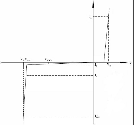
Ⅵ TVS diode characteristic curve and circuits
TVS diode characteristic curve:
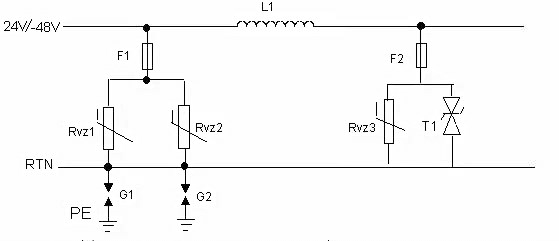
DC power protection design
Outdoor network port protection circuit
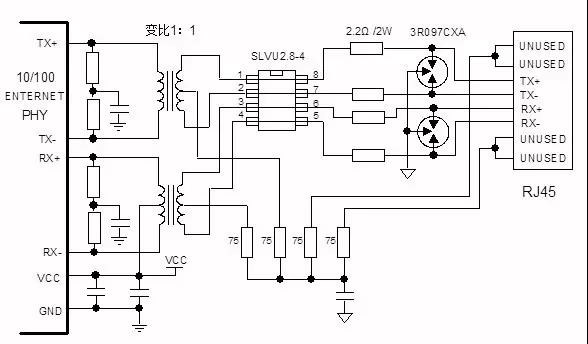
Note that the parasitic capacitance of the TVS tube may affect signal integrity. You can use a varistor to be placed on the transformer tap as a protection circuit to support higher-speed network port design.
232 Protection circuit design

485 protection circuit design

Ⅶ How to choose TVS diodes?
(1) Determine the maximum DC or continuous working voltage of the protected circuit, the rated standard voltage of the circuit, and the "high end" tolerance.
(2) TVS rated reverse shutdown VWM should be greater than or equal to the maximum working voltage of the protected circuit. If the selected VWM is too low, the device may enter an avalanche or the reverse leakage current may affect the normal operation of the circuit. Connect the sub-voltage in series and connect the sub-current in parallel.
(3) The maximum clamping voltage VC of TVS should be less than the damage voltage of the protected circuit.
(4) Within the specified pulse duration, the maximum peak pulse power consumption PM of TVS must be greater than the peak pulse power that may appear in the protected circuit. After determining the maximum clamping voltage, its peak pulse current should be greater than the transient surge current.
(5) For the protection of the data interface circuit, attention must also be paid to selecting TVS devices with suitable capacitance C.
(6) Select the polarity and package structure of TVS according to the application. It is more reasonable to use bipolar TVS for the AC circuit; it is more advantageous to use TVS array for multi-line protection.
(7) Temperature considerations. The transient voltage suppressor can work between -55℃~+150℃. If TVS is required to work at changing temperature, its reverse leakage current ID increases. The power consumption decreases with the increase of TVS junction temperature, from +25°C to +175°C, approximately a linear decrease of 50%. The through voltage VBR increases with a certain coefficient as the temperature increases. Therefore, it is necessary to consult relevant product information and consider the influence of temperature changes on its characteristics.
The best way to deal with the damage of the transient pulse to the component is to divert the transient current from the inductive component. The TVS diode is connected in parallel with the protected circuit on the circuit board. When the instantaneous voltage exceeds the normal working voltage of the circuit, the TVS diode will produce an avalanche, providing an ultra-low resistance path for the instantaneous current. As a result, the instantaneous current is drawn through the diode. When the instantaneous pulse ends, the TVS diode automatically returns to the high resistance state, and the entire circuit enters the normal voltage. After many components are subjected to multiple shocks, their parameters and performance will be degraded, and as long as they work within a limited range, the diode will not be damaged or degraded.
It can be seen from the above process that when selecting TVS diodes, you must pay attention to the selection of the following parameters:
1. The minimum breakdown voltage VBR and breakdown of current IR. VBR is the minimum breakdown voltage of TVS. At 25°C, TVS will not produce an avalanche below this voltage. When the TVS flows through the specified 1mA current (IR), the voltage applied to the two poles of the TVS is its minimum breakdown voltage V BR. According to the degree of dispersion between the VBR of TVS and the standard value, VBR can be divided into 5% and 10%. For 5% VBR, V WM = 0.85VBR; for 10% VBR, V WM = 0.81VBR. In order to meet the IEC61000-4-2 international standard, TVS diodes must be able to handle a minimum of 8kV (contact) and 15kV (air) ESD impact. Some semiconductor manufacturers use higher impact resistance standards on their products.
2. Maximum reverse leakage current ID and rated reverse cut-off voltage VWM. VWM is the voltage that the diode can withstand under normal conditions. This voltage should be greater than or equal to the normal working voltage of the protected circuit, otherwise, the diode will continuously cut off the loop voltage. But it needs to be as close as possible to the normal working voltage of the protected circuit so that the entire circuit will not face the threat of overvoltage before the TVS works. When this rated reverse cut-off voltage VWM is applied between the two poles of TVS, it is in the reverse cut-off state, and the current flowing through it should be less than or equal to its maximum reverse leakage current ID.
3. The maximum clamping voltage VC and the maximum peak pulse current IPP. When the pulse peak current IPP with a duration of 20ms flows through the TVS, the maximum peak voltage that appears at both ends is VC. VC and IPP reflect the surge suppression capability of TVS. The ratio of VC to VBR is called the clamping factor, which is generally between 1.2 and 1.4. VC is the voltage provided by the diode in the off state, that is, the voltage that passes through the TVS in the ESD impact state. It cannot be greater than the withstand limit voltage of the protected circuit, otherwise, the components are in danger of being damaged.
4. Pppm rated pulse power is based on the maximum cut-off voltage and the peak pulse current. For handheld devices, a 500W TVS is generally sufficient. The maximum peak pulse power consumption PM is the maximum peak pulse power consumption that the TVS can withstand. Under a certain maximum clamping voltage, the greater the power consumption PM, the greater the surge current capacity. Under a specific power consumption PM, the lower the clamping voltage VC, the greater the surge current capacity. In addition, the peak pulse power consumption is also related to pulse shape, duration, and ambient temperature. Moreover, the transient pulse that TVS can withstand is non-repetitive, and the pulse repetition frequency (the ratio of duration to intermittent time) specified by the component is 0.01%. If repetitive pulses appear in the circuit, the accumulation of pulse power should be considered, which may damage the TVS.
5. The amount of capacitor C. The amount of capacitor C is determined by the TVS avalanche junction cross-section, which is measured at a specific frequency of 1MHz. The size of C is proportional to the current capacity of the TVS. Therefore, C is an important parameter for selecting TVS for data interface circuits. For circuits with higher data/signal frequencies, the capacitors of the diodes will interfere more with the circuit, forming noise or attenuating the signal strength. Therefore, the capacitor range of the selected component needs to be determined according to the characteristics of the circuit. Generally, the capacitor should be as small as possible for the high-frequency circuit (such as LCTVS, low-capacitor TVS, the capacitor is not more than 3pF), and the capacitor for the circuit that does not require high capacitors can be selected higher than 40pF.
Article Recommended:
Switching Diodes Basics: Working, Types and Circuit Analysis
 UTMEL
UTMEL
We are the professional distributor of electronic components, providing a large variety of products to save you a lot of time, effort, and cost with our efficient self-customized service. careful order preparation fast delivery service
 All You Need to Know About Rectifier CircuitUTMEL24 April 202517462
All You Need to Know About Rectifier Circuit
Read More 15 Key Elements of Diode SelectionUTMEL26 November 202118822
Hello everyone, I am Rose. Welcome back to the new post today. Diodes are one of the most common components in our circuit boards. So, what factors should be considered when selecting models?
Read More What is a PIN Diode?UTMEL04 February 202110093
While diodes with a simple PN junction are by far the most common type of diode in operation, in a variety of applications, other forms of diode may be used. The PIN diode is one type that is used for a number of circuits. In a variety of places, this diode type is used. For RF switching, the PIN diode is very fine, and the PIN structure in photodiodes is very useful as well.
Read More Microwave Diode: Introduction and TypesUTMEL07 January 202125845
Microwave diodes are diodes that work in the microwave frequency band. It is a solid-state microwave device. Microwave band usually refers to the frequency from 300 MHz to 3000 GHz. After the discovery of the point contact diode effect at the end of the 19th century, microwave diodes such as PIN diodes, varactor diodes, and Schottky diode tubes appeared one after another. Microwave diodes have the advantages of small size and high reliability, and are used in microwave oscillation, amplification, frequency conversion, switching, phase shifting and modulation.
Read More What Determines the Maximum Operating Frequency of a Diode?UTMEL29 June 202212815
Hello, wish you a wonderful day. In this essay, we first pose the following query: what determines the diode's maximum operating frequency? In regards to the solution, the first thing we need to understand is that the junction capacitance and the reverse recovery time of the diode are two distinct concepts. The charging and discharging times of the junction capacitance cannot match the reverse recovery time. You say that, why? Let's start by taking a look at these facts.
Read More
Subscribe to Utmel !
![BLM21BD331SH1D]() BLM21BD331SH1D
BLM21BD331SH1DMurata Electronics
![FBMH1608HM101-TV]() FBMH1608HM101-TV
FBMH1608HM101-TVTaiyo Yuden
![BLM21BB331SN1D]() BLM21BB331SN1D
BLM21BB331SN1DMurata Electronics
![FBMH3216HM221NT]() FBMH3216HM221NT
FBMH3216HM221NTTaiyo Yuden
![742792651]() 742792651
742792651Würth Elektronik
![BLM03HB191SN1D]() BLM03HB191SN1D
BLM03HB191SN1DMurata Electronics
![ZCAT1325-0530A]() ZCAT1325-0530A
ZCAT1325-0530ATDK Corporation
![LFCN-2600D]() LFCN-2600D
LFCN-2600DMini-Circuits
![HF70ACC322513-T]() HF70ACC322513-T
HF70ACC322513-TTDK Corporation
![ACH32C-104-T001]() ACH32C-104-T001
ACH32C-104-T001TDK Corporation