
 Product
 Brand
Brand Articles
 Tools
Tools
M24C64-R I²C bus EEPROM: Pinout, Equivalent and Datasheet


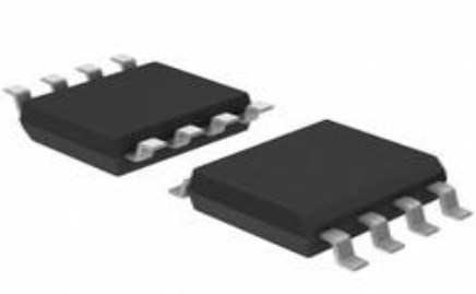
Surface Mount 8 Pin Memory IC M24C64 64 kb kb 4.9mm mm 3mA mA
The M24C64 is a 64-Kbit I2C-compatible EEPROM (Electrically Erasable PROgrammable Memory) organized as 8 K × 8 bits. Over an ambient temperature range of -40 °C / +85 °C, the M24C64-R can operate with a supply voltage from 1.8 V to 5.5 V. Furthermore, Huge range of Semiconductors, Capacitors, Resistors and IcS in stock. Welcome RFQ.

What Is EEPROM?
M24C64-R Pinout
The following figure is the diagram of M24C64-R Pinout.

Pinout
M24C64-R CAD Model
The followings are M24C64-R Symbol, Footprint, and 3D Model.

PCB Symbol

PCB Footprint

3D Model
M24C64-R Overview
The M24C64 is a 64-Kbit I2C-compatible EEPROM (Electrically Erasable PROgrammable Memory) organized as 8 K × 8 bits. Over an ambient temperature range of -40 °C / +85 °C, the M24C64-R can operate with a supply voltage from 1.8 V to 5.5 V.
This article provides you with a basic overview of the M24C64-R I²C bus EEPROM, including its pin descriptions, features and specifications, etc., to help you quickly understand what M24C64-R is.
M24C64-R Features
● Compatible with all I2C bus modes:
◆ 1 MHz
◆ 400 kHz
◆ 100 kHz
● Memory array:
◆ 64 Kbit (8 Kbyte) of EEPROM
◆ Page size: 32 byte
● Single supply voltage: 1.8 V to 5.5 V over –40 °C / +85 °C
● Write:
◆ Byte Write within 5 ms
◆ Page Write within 5 ms
● Random and sequential Read modes
● Write protect of the whole memory array
● Enhanced ESD/Latch-Up protection
● More than 4 million Write cycles
● More than 200-years data retention
Specifications
- TypeParameter
- Lifecycle Status
Lifecycle Status refers to the current stage of an electronic component in its product life cycle, indicating whether it is active, obsolete, or transitioning between these states. An active status means the component is in production and available for purchase. An obsolete status indicates that the component is no longer being manufactured or supported, and manufacturers typically provide a limited time frame for support. Understanding the lifecycle status is crucial for design engineers to ensure continuity and reliability in their projects.
ACTIVE (Last Updated: 7 months ago) - Factory Lead Time13 Weeks
- Contact Plating
Contact plating (finish) provides corrosion protection for base metals and optimizes the mechanical and electrical properties of the contact interfaces.
Gold - Mount
In electronic components, the term "Mount" typically refers to the method or process of physically attaching or fixing a component onto a circuit board or other electronic device. This can involve soldering, adhesive bonding, or other techniques to secure the component in place. The mounting process is crucial for ensuring proper electrical connections and mechanical stability within the electronic system. Different components may have specific mounting requirements based on their size, shape, and function, and manufacturers provide guidelines for proper mounting procedures to ensure optimal performance and reliability of the electronic device.
Surface Mount - Mounting Type
The "Mounting Type" in electronic components refers to the method used to attach or connect a component to a circuit board or other substrate, such as through-hole, surface-mount, or panel mount.
Surface Mount - Package / Case
refers to the protective housing that encases an electronic component, providing mechanical support, electrical connections, and thermal management.
8-SOIC (0.154, 3.90mm Width) - Number of Pins8
- Manufacturer Package Identifier
The Manufacturer Package Identifier is a unique code or label assigned by the manufacturer to identify a specific package or housing style of an electronic component. This identifier helps in distinguishing between different package types of the same component, such as integrated circuits, transistors, or diodes. It typically includes information about the package dimensions, lead configuration, and other physical characteristics of the component. The Manufacturer Package Identifier is crucial for ensuring compatibility and proper assembly of electronic components in various devices and circuits.
SO8N-SO-A - Memory TypesNon-Volatile
- Usage LevelIndustrial grade
- Operating Temperature
The operating temperature is the range of ambient temperature within which a power supply, or any other electrical equipment, operate in. This ranges from a minimum operating temperature, to a peak or maximum operating temperature, outside which, the power supply may fail.
-40°C~85°C TA - Packaging
Semiconductor package is a carrier / shell used to contain and cover one or more semiconductor components or integrated circuits. The material of the shell can be metal, plastic, glass or ceramic.
Tape & Reel (TR) - JESD-609 Code
The "JESD-609 Code" in electronic components refers to a standardized marking code that indicates the lead-free solder composition and finish of electronic components for compliance with environmental regulations.
e4 - Part Status
Parts can have many statuses as they progress through the configuration, analysis, review, and approval stages.
Active - Moisture Sensitivity Level (MSL)
Moisture Sensitivity Level (MSL) is a standardized rating that indicates the susceptibility of electronic components, particularly semiconductors, to moisture-induced damage during storage and the soldering process, defining the allowable exposure time to ambient conditions before they require special handling or baking to prevent failures
1 (Unlimited) - Number of Terminations8
- ECCN Code
An ECCN (Export Control Classification Number) is an alphanumeric code used by the U.S. Bureau of Industry and Security to identify and categorize electronic components and other dual-use items that may require an export license based on their technical characteristics and potential for military use.
EAR99 - Voltage - Supply
Voltage - Supply refers to the range of voltage levels that an electronic component or circuit is designed to operate with. It indicates the minimum and maximum supply voltage that can be applied for the device to function properly. Providing supply voltages outside this range can lead to malfunction, damage, or reduced performance. This parameter is critical for ensuring compatibility between different components in a circuit.
1.8V~5.5V - Terminal Position
In electronic components, the term "Terminal Position" refers to the physical location of the connection points on the component where external electrical connections can be made. These connection points, known as terminals, are typically used to attach wires, leads, or other components to the main body of the electronic component. The terminal position is important for ensuring proper connectivity and functionality of the component within a circuit. It is often specified in technical datasheets or component specifications to help designers and engineers understand how to properly integrate the component into their circuit designs.
DUAL - Number of Functions1
- Supply Voltage
Supply voltage refers to the electrical potential difference provided to an electronic component or circuit. It is crucial for the proper operation of devices, as it powers their functions and determines performance characteristics. The supply voltage must be within specified limits to ensure reliability and prevent damage to components. Different electronic devices have specific supply voltage requirements, which can vary widely depending on their design and intended application.
2.5V - Terminal Pitch
The center distance from one pole to the next.
1.27mm - Base Part Number
The "Base Part Number" (BPN) in electronic components serves a similar purpose to the "Base Product Number." It refers to the primary identifier for a component that captures the essential characteristics shared by a group of similar components. The BPN provides a fundamental way to reference a family or series of components without specifying all the variations and specific details.
M24C64 - Pin Count
a count of all of the component leads (or pins)
8 - Operating Supply Voltage
The voltage level by which an electrical system is designated and to which certain operating characteristics of the system are related.
5V - Memory Size
The memory capacity is the amount of data a device can store at any given time in its memory.
64Kb 8K x 8 - Nominal Supply Current
Nominal current is the same as the rated current. It is the current drawn by the motor while delivering rated mechanical output at its shaft.
3mA - Clock Frequency
Clock frequency, also known as clock speed, refers to the rate at which a processor or electronic component can execute instructions. It is measured in hertz (Hz) and represents the number of cycles per second that the component can perform. A higher clock frequency typically indicates a faster processing speed and better performance. However, it is important to note that other factors such as architecture, efficiency, and workload also play a significant role in determining the overall performance of a component. In summary, clock frequency is a crucial parameter that influences the speed and efficiency of electronic components in processing data and executing tasks.
1MHz - Access Time
Access time in electronic components refers to the amount of time it takes for a system to retrieve data from memory or storage once a request has been made. It is typically measured in nanoseconds or microseconds and indicates the speed at which data can be accessed. Lower access time values signify faster performance, allowing for more efficient processing in computing systems. Access time is a critical parameter in determining the overall responsiveness of electronic devices, particularly in applications requiring quick data retrieval.
450ns - Memory Format
Memory Format in electronic components refers to the specific organization and structure of data storage within a memory device. It defines how data is stored, accessed, and managed within the memory module. Different memory formats include RAM (Random Access Memory), ROM (Read-Only Memory), and various types of flash memory. The memory format determines the speed, capacity, and functionality of the memory device, and it is crucial for compatibility with other components in a system. Understanding the memory format is essential for selecting the right memory module for a particular application or device.
EEPROM - Memory Interface
An external memory interface is a bus protocol for communication from an integrated circuit, such as a microprocessor, to an external memory device located on a circuit board.
I2C - Write Cycle Time - Word, Page
Write Cycle Time - Word, Page refers to the duration required to write data to a specific memory cell or a page of memory in electronic components, particularly in non-volatile memories like Flash or EEPROM. It indicates the time taken to complete a writing operation for a single word or an entire page of data. This parameter is crucial for determining the performance and speed of memory devices in applications where quick data storage is essential. It impacts the overall efficiency in data handling, affecting both read and write speeds in memory-related operations.
5ms - Density
In electronic components, "Density" refers to the mass or weight of a material per unit volume. It is a physical property that indicates how tightly packed the atoms or molecules are within the material. The density of a component can affect its performance and characteristics, such as its strength, thermal conductivity, and electrical properties. Understanding the density of electronic components is important for designing and manufacturing processes to ensure optimal performance and reliability.
64 kb - Standby Current-Max
Standby Current-Max refers to the maximum amount of current that an electronic component or device consumes while in a low-power standby mode. This parameter is critical for power management, especially in battery-operated devices, as it indicates how efficiently the device can conserve energy when not actively in use. A lower Standby Current-Max value is typically desirable, as it contributes to longer battery life and reduced energy consumption. Manufacturers specify this value to help engineers select components that meet specific power efficiency requirements in their designs.
0.000001A - Parallel/Serial
The parameter "Parallel/Serial" in electronic components refers to the method of data transmission or communication within the component. In parallel communication, multiple bits of data are transmitted simultaneously over multiple channels or wires. This allows for faster data transfer rates but requires more physical connections and can be more susceptible to signal interference.On the other hand, in serial communication, data is transmitted sequentially over a single channel or wire. While serial communication may have slower data transfer rates compared to parallel communication, it is more cost-effective, requires fewer connections, and is less prone to signal interference.The choice between parallel and serial communication depends on the specific requirements of the electronic component and the overall system design, balancing factors such as speed, cost, complexity, and reliability.
SERIAL - Serial Bus Type
Serial bus type refers to the method by which data is transmitted between components in an electronic system using a serial communication protocol. It involves the sequential transfer of data bits over a single channel or wire, allowing for a reduced number of interconnections compared to parallel communication. Common examples of serial bus types include I2C, SPI, USB, and UART, each with its own specific protocol and applications. The choice of serial bus type can affect the speed, complexity, and power consumption of the communication between devices.
I2C - Endurance
In electronic components, "Endurance" refers to the ability of a component to withstand repeated cycles of operation without degradation in performance or failure. It is a crucial parameter, especially in components that are subjected to frequent switching or high levels of stress during operation. Endurance testing is often conducted to evaluate the reliability and durability of electronic components under real-world conditions. Components with high endurance ratings are more likely to have a longer lifespan and provide consistent performance over time. Manufacturers typically provide endurance specifications in datasheets to help engineers and designers select components that meet the required durability for their applications.
1000000 Write/Erase Cycles - Write Cycle Time-Max (tWC)
The parameter "Write Cycle Time-Max (tWC)" in electronic components refers to the maximum amount of time it takes for data to be written to a memory cell or storage device. It is a crucial specification in devices such as EEPROMs, flash memory, and other non-volatile memory technologies. The tWC value indicates the longest duration required for a write operation to be completed successfully, ensuring that the data is stored accurately and reliably. Designers and engineers use this parameter to optimize performance and ensure proper functioning of the electronic component within the specified time constraints.
5ms - Data Retention Time-Min
The parameter "Data Retention Time-Min" in electronic components refers to the minimum amount of time that data can be stored in a non-volatile memory device without requiring a refresh or rewrite operation to maintain its integrity. This parameter is crucial for applications where data integrity and reliability are essential, such as in embedded systems, IoT devices, and critical infrastructure. A longer data retention time indicates a more stable memory device that can retain data for extended periods without degradation or loss. It is important to consider the data retention time when selecting memory components for specific applications to ensure data reliability and longevity.
40 - Write Protection
Write protection is a feature found in electronic components, such as memory devices, that prevents data from being modified or erased. When write protection is enabled, the data stored in the component is locked and cannot be altered, ensuring the integrity and security of the information. This feature is commonly used in devices like USB flash drives, SD cards, and EEPROMs to prevent accidental data loss or unauthorized access. Write protection can be implemented through hardware mechanisms, such as physical switches or jumpers, or through software settings that restrict write access to the component.
HARDWARE - Ambient Temperature Range High
This varies from person to person, but it is somewhere between 68 and 77 degrees F on average. The temperature setting that is comfortable for an individual may fluctuate with humidity and outside temperature as well. The temperature of an air conditioned room can also be considered ambient temperature.
85°C - I2C Control Byte
The I2C Control Byte is a specific byte of data used in the Inter-Integrated Circuit (I2C) communication protocol for electronic components. It is a crucial part of the data transmission process as it contains information such as the address of the device being accessed and the type of operation to be performed, such as read or write. The Control Byte is typically the first byte sent in an I2C communication sequence and helps establish communication between the master and slave devices on the bus. By interpreting the Control Byte, devices can effectively communicate and exchange data in a synchronized manner within an I2C network.
1010DDDR - Height1.75mm
- Length4.9mm
- Width3.9mm
- Radiation Hardening
Radiation hardening is the process of making electronic components and circuits resistant to damage or malfunction caused by high levels of ionizing radiation, especially for environments in outer space (especially beyond the low Earth orbit), around nuclear reactors and particle accelerators, or during nuclear accidents or nuclear warfare.
No - RoHS Status
RoHS means “Restriction of Certain Hazardous Substances” in the “Hazardous Substances Directive” in electrical and electronic equipment.
ROHS3 Compliant - Lead Free
Lead Free is a term used to describe electronic components that do not contain lead as part of their composition. Lead is a toxic material that can have harmful effects on human health and the environment, so the electronics industry has been moving towards lead-free components to reduce these risks. Lead-free components are typically made using alternative materials such as silver, copper, and tin. Manufacturers must comply with regulations such as the Restriction of Hazardous Substances (RoHS) directive to ensure that their products are lead-free and environmentally friendly.
Lead Free
M24C64-R Functional Block Diagram
The following is the Block Diagram of M24C64-R.

Block diagram
The following is the Logic diagram of M24C64-R.

Logic diagram
M24C64-R Equivalent
| Model number | Manufacturer | Description |
| M24C64-RMN6G/B | STMicroelectronics | 8KX8 I2C/2-WIRE SERIAL EEPROM, PDSO8, 0.150 INCH, ROHS COMPLIANT, PLASTIC, SOP-8 |
| M24C64-RMN5G/B | STMicroelectronics | 8KX8 I2C/2-WIRE SERIAL EEPROM, PDSO8, 0.150 INCH, ROHS COMPLIANT, PLASTIC, SOP-8 |
| M24C64-RMN5G/P | STMicroelectronics | 8KX8 I2C/2-WIRE SERIAL EEPROM, PDSO8, 0.150 INCH, ROHS COMPLIANT, PLASTIC, SOP-8 |
| M24C64-DRMN8G/K | STMicroelectronics | I2C/2-WIRE SERIAL EEPROM |
| M24C64-DRMN8P/K | STMicroelectronics | I2C/2-WIRE SERIAL EEPROM |
| M24C64-RMN1 | STMicroelectronics | 8KX8 I2C/2-WIRE SERIAL EEPROM, PDSO8, 0.150 INCH, PLASTIC, SO-8 |
| M24C64-RMN5/B | STMicroelectronics | 8KX8 I2C/2-WIRE SERIAL EEPROM, PDSO8, 0.150 INCH, PLASTIC, SOP-8 |
| M24C64-RMN3T/C | STMicroelectronics | 8KX8 I2C/2-WIRE SERIAL EEPROM, PDSO8, 0.150 INCH, PLASTIC, SOP-8 |
| M24C64-DRMN8TP/K | STMicroelectronics | 64-Kbit serial I2C bus EEPROM 105°C operation |
| M24C64-RMN3/B | STMicroelectronics | 8KX8 I2C/2-WIRE SERIAL EEPROM, PDSO8, 0.150 INCH, PLASTIC, SOP-8 |
Parts with Similar Specs
- ImagePart NumberManufacturerPackage / CaseNumber of PinsDensityAccess TimeSupply VoltageWrite Cycle Time - Word, PageTerminal PitchMoisture Sensitivity Level (MSL)View Compare
![M24C64-RMN6TP]()
M24C64-RMN6TP
8-SOIC (0.154, 3.90mm Width)
8
64 kb
450ns
2.5 V
5ms
1.27 mm
1 (Unlimited)
![CAT24C64WI-GT3]()
8-SOIC (0.154, 3.90mm Width)
8
64 kb
400ns
1.8 V
5ms
1.27 mm
1 (Unlimited)
![M24C64-WMN6P]()
8-SOIC (0.154, 3.90mm Width)
8
64 kb
400ns
5 V
5ms
1.27 mm
1 (Unlimited)
![CAT24C64WI-G]()
8-SOIC (0.154, 3.90mm Width)
8
64 kb
450ns
5 V
5ms
1.27 mm
1 (Unlimited)
![24LC64T-I/SN]()
8-SOIC (0.154, 3.90mm Width)
8
64 kb
900ns
5 V
5ms
1.27 mm
1 (Unlimited)


M24C64-R Package
The following diagrams show the M24C64-R Package.

View A

View B

View C

View D
M24C64-R Package Recommended Footprint
The following diagram shows the M24C64-R Package Recommended Footprint.

Package Recommended Footprint
M24C64-R Manufacturer
STMicroelectronics is a global independent semiconductor company and is a leader in developing and delivering semiconductor solutions across the spectrum of microelectronics applications. An unrivaled combination of silicon and system expertise, manufacturing strength, Intellectual Property (IP) portfolio and strategic partners positions the Company at the forefront of System-on-Chip (SoC) technology and its products play a key role in enabling today's convergence trends.
Datasheet PDF
- Datasheets :
- PCN Other :
How many pins of M24C64-RMN6TP?
8 Pins.
What’s the operating temperature of M24C64-RMN6TP?
-40°C~85°C TA.
What is the essential property of the M24C64-R?
The M24C64 is a 64-Kbit I2C-compatible EEPROM (Electrically Erasable PROgrammable Memory) organized as 8 K × 8 bits. Over an ambient temperature range of -40 °C / +85 °C, the M24C64-R can operate with a supply voltage from 1.8 V to 5.5 V.
 A Comprehensive Guide to LTM2882HY-3#PBF Transceiver Module
06 March 2024242
 TLV5638IDR:DAC, Pinout, Datasheet
16 February 2022979
 ATTINY85 8-bit Microcontroller: Architecture, Pinout, and Design Guide
15 January 20261432
 ATtiny13A 8-Bit Microcontroller: Datasheet, Specifications, Pinout
28 September 20217500
 L78L05ABUTR Regulator: Features, Applications and Datasheet
21 December 2023608
 TMS470R1A288 16/32-Bit RISC Flash Microcontroller: Technical Overview
29 February 2024175
 A Practical Guide to STM32F429IIT6 in Embedded Systems
24 July 2025242
 TL431AIDBZR Shunt Regulator: Shunt Regulator, Datasheet, Circuit
09 February 20222956
 Basis of Fiber Optic and Fiber Optic Communication
22 October 20215222
 Semiconductor Industry's Uphill Battle Towards Net Zero
22 September 20232102
 Working Principles and Applications of Pressure Sensors
07 April 202536048
 What are the Types of Phone Displays?
07 July 20214151
 Introduction to RAID (Redundant Arrays of Independent Disks)
01 July 20219150
 Power Semiconductor Procurement After the Nexperia Shake-Up—NXP for Stability, ON for Technology, or Nexperia for Value?
04 November 20254495
 Will AI Eventually Compete With Humans for Energy Resources?
14 February 20234349
 Sourcing GaN Power Devices for AI Servers, EVs, and Industrial Applications
10 July 202690
STMicroelectronics
In Stock: 96025
United States
China
Canada
Japan
Russia
Germany
United Kingdom
Singapore
Italy
Hong Kong(China)
Taiwan(China)
France
Korea
Mexico
Netherlands
Malaysia
Austria
Spain
Switzerland
Poland
Thailand
Vietnam
India
United Arab Emirates
Afghanistan
Åland Islands
Albania
Algeria
American Samoa
Andorra
Angola
Anguilla
Antigua & Barbuda
Argentina
Armenia
Aruba
Australia
Azerbaijan
Bahamas
Bahrain
Bangladesh
Barbados
Belarus
Belgium
Belize
Benin
Bermuda
Bhutan
Bolivia
Bonaire, Sint Eustatius and Saba
Bosnia & Herzegovina
Botswana
Brazil
British Indian Ocean Territory
British Virgin Islands
Brunei
Bulgaria
Burkina Faso
Burundi
Cabo Verde
Cambodia
Cameroon
Cayman Islands
Central African Republic
Chad
Chile
Christmas Island
Cocos (Keeling) Islands
Colombia
Comoros
Congo
Congo (DRC)
Cook Islands
Costa Rica
Côte d’Ivoire
Croatia
Cuba
Curaçao
Cyprus
Czechia
Denmark
Djibouti
Dominica
Dominican Republic
Ecuador
Egypt
El Salvador
Equatorial Guinea
Eritrea
Estonia
Eswatini
Ethiopia
Falkland Islands
Faroe Islands
Fiji
Finland
French Guiana
French Polynesia
Gabon
Gambia
Georgia
Ghana
Gibraltar
Greece
Greenland
Grenada
Guadeloupe
Guam
Guatemala
Guernsey
Guinea
Guinea-Bissau
Guyana
Haiti
Honduras
Hungary
Iceland
Indonesia
Iran
Iraq
Ireland
Isle of Man
Israel
Jamaica
Jersey
Jordan
Kazakhstan
Kenya
Kiribati
Kosovo
Kuwait
Kyrgyzstan
Laos
Latvia
Lebanon
Lesotho
Liberia
Libya
Liechtenstein
Lithuania
Luxembourg
Macao(China)
Madagascar
Malawi
Maldives
Mali
Malta
Marshall Islands
Martinique
Mauritania
Mauritius
Mayotte
Micronesia
Moldova
Monaco
Mongolia
Montenegro
Montserrat
Morocco
Mozambique
Myanmar
Namibia
Nauru
Nepal
New Caledonia
New Zealand
Nicaragua
Niger
Nigeria
Niue
Norfolk Island
North Korea
North Macedonia
Northern Mariana Islands
Norway
Oman
Pakistan
Palau
Palestinian Authority
Panama
Papua New Guinea
Paraguay
Peru
Philippines
Pitcairn Islands
Portugal
Puerto Rico
Qatar
Réunion
Romania
Rwanda
Samoa
San Marino
São Tomé & Príncipe
Saudi Arabia
Senegal
Serbia
Seychelles
Sierra Leone
Sint Maarten
Slovakia
Slovenia
Solomon Islands
Somalia
South Africa
South Sudan
Sri Lanka
St Helena, Ascension, Tristan da Cunha
St. Barthélemy
St. Kitts & Nevis
St. Lucia
St. Martin
St. Pierre & Miquelon
St. Vincent & Grenadines
Sudan
Suriname
Svalbard & Jan Mayen
Sweden
Syria
Tajikistan
Tanzania
Timor-Leste
Togo
Tokelau
Tonga
Trinidad & Tobago
Tunisia
Turkey
Turkmenistan
Turks & Caicos Islands
Tuvalu
U.S. Outlying Islands
U.S. Virgin Islands
Uganda
Ukraine
Uruguay
Uzbekistan
Vanuatu
Vatican City
Venezuela
Wallis & Futuna
Yemen
Zambia
Zimbabwe
![M24C16-MN6]() M24C16-MN6
M24C16-MN6STMicroelectronics
![M48Z12-150PC1]() M48Z12-150PC1
M48Z12-150PC1STMicroelectronics
![M24512-RMN6TP]() M24512-RMN6TP
M24512-RMN6TPSTMicroelectronics
![M24C64-WMN6TP]() M24C64-WMN6TP
M24C64-WMN6TPSTMicroelectronics
![M93C46-WMN6TP]() M93C46-WMN6TP
M93C46-WMN6TPSTMicroelectronics
![M95512-WMN6TP]() M95512-WMN6TP
M95512-WMN6TPSTMicroelectronics
![M24C04-WMN6TP]() M24C04-WMN6TP
M24C04-WMN6TPSTMicroelectronics
![M24512-WMN6TP]() M24512-WMN6TP
M24512-WMN6TPSTMicroelectronics
![M24C02-WMN6TP]() M24C02-WMN6TP
M24C02-WMN6TPSTMicroelectronics
![M24C32-WMN6TP]() M24C32-WMN6TP
M24C32-WMN6TPSTMicroelectronics
