
 Product
 Brand
Brand Articles
 Tools
Tools
How to Design an Accurate DC Power Supply

How to use a DC Power Supply | Basic Electronics
Topics Covered in This Article:
Ⅱ. Current and Voltage Sensing
Ⅲ. Analog-to-Digital Converter (ADC)
Application Areas: Test and measurement applications such as battery testing, electrochemical impedance spectroscopy (EIS), and semiconductor testing require accurate current and voltage output DC power supplies. When the ambient temperature changes by ±5°C, the current and voltage control accuracy of the device needs to be better than ±0.02% of the full scale. This accuracy largely depends on the temperature drift of the current sense resistor and amplifier.
In this article, you will learn how different components affect system accuracy and how to select suitable components for the design of precision DC power supplies. We will explore the complete design process from output drivers to control loops.
Ⅰ. Output Driver
Figure 1 is a block diagram of a power supply, including output drivers, current and voltage sensing circuits, control loops, analog-to-digital converters (ADC), and digital-to-analog converters (DAC). The choice of output driver depends on the output accuracy, noise, and power level.

Figure 1: Typical Block Diagram of a DC Power Supply
Low-Power Applications (<5W): Linear power supplies can be used as output drivers for low power consumption or low noise applications. Power operational amplifiers (op-amps) have integrated thermal protection and overcurrent protection functions, making them suitable for low-power applications.
High-Power Applications: Due to power dissipation issues, it is challenging to use a linear output driver at higher output power levels. Therefore, a synchronous buck converter is needed to achieve higher output power, with a large filter on the output side to achieve 0.01% full-scale accuracy. For example, using a buck converter, an accuracy of 500 µV can be achieved in the 5V output range.
Important Note: You need to confirm that there are no pulse-skipping mode and diode emulation mode in the converter that would increase the output ripple at light loads. Texas Instruments' C2000 real-time microcontroller (MCU) is ideal for precision synchronous buck converter power supplies because you can disable unwanted functions in software.
Ⅱ. Current and Voltage Sensing
High-precision current shunt resistors and low-drift instrumentation amplifiers can measure output current. The input offset voltage error and gain error of the instrumentation amplifier are not a problem because these two errors are accounted for during system calibration. However, offset voltage and gain drift, output noise, and gain nonlinearity are difficult to calibrate. These errors should be considered when selecting a current sense amplifier.
Equation 1 calculates the overall unadjusted error of the current sense amplifier, as shown in Table 1. The error from the common-mode rejection ratio is relatively small, so it can be ignored.

Table 1: Overall Unadjusted Error of Current Sense Amplifiers
Among the amplifiers listed in the table, INA188 has the smallest error. The error calculation uses a temperature change of ±5°C and selects 100mΩ and 1mΩ current sense resistors for 1A and 25A outputs, respectively.
Voltage Monitoring: You can use a differential amplifier or instrumentation amplifier to monitor the load voltage very accurately. The amplifier senses the output voltage and ground of the two loads, eliminating errors due to any voltage drop in the cable. System calibration will adjust the offset voltage and gain error of the amplifier, leaving only the input temperature drift.
You can divide the temperature drift by the full-scale voltage and calculate the drift in parts per million (ppm). For example, for 2.5V full scale and 1µV/°C temperature drift, the drift will be 0.4ppm/°C. If you need lower output voltage drift, you can choose a zero-drift operational amplifier (such as OPA188), which has a maximum input temperature drift of 85nV/°C. However, a precision operational amplifier with a temperature drift of 1µV/°C is sufficient for most applications.
Ⅲ. Analog-to-Digital Converter (ADC)
The ADC offset voltage and gain error are adjusted during system calibration. Errors caused by ADC drift and nonlinearity are difficult to calibrate. Table 2 compares the errors of three different high-precision delta-sigma ADCs when the temperature changes by ±5°C.
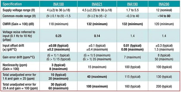
Table 2: Overall Unadjusted Error of ADCs
Among the ADCs listed in the table, ADS131M02 has the smallest error. The error calculation does not include ADC output noise and voltage reference errors.
Noise Optimization: You can significantly reduce the error caused by noise by increasing the oversampling rate of the ADC. Low noise (<0.23ppm peak-to-peak) and low-temperature drift voltage references (<2ppm/°C) (such as REF70) are sufficient to meet the needs of DC power applications.
Long-Term Stability: During 0 to 1,000 hours of operation, the REF70 only has a long-term drift of 28 ppm. In the subsequent 1,000 hours of operation, the drift is significantly lower than 28 ppm, ensuring long-term stability.
Ⅳ. Control Loop
Figure 2 shows the analog control loop of the power supply. Even if you don't need a constant current output, keeping the constant current loop will help with short-circuit protection. The constant current loop limits the output current by reducing the output voltage, and the current limit can be programmed through the IREF setting.
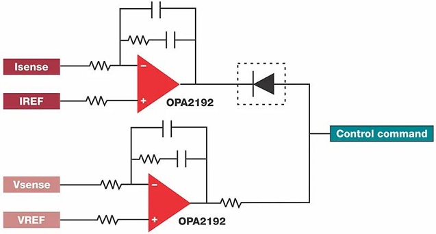
Figure 2: Schematic Diagram of Constant Current and Constant Voltage Loops
Loop Switching Mechanism: Using a diode between the constant current and constant voltage loops helps achieve constant voltage to constant current conversion and vice versa. Multiplexer-friendly operational amplifiers are suitable for constant current and constant voltage loops, avoiding short circuits between amplifier inputs during open-loop operation.
When any control loop is in an open-loop state, the operational amplifier may generate a differential voltage greater than 0.7V at its input pins. Non-multiplexer-friendly operational amplifiers have anti-parallel diodes at the input pins, and the differential voltage is not allowed to exceed the diode voltage drop. Therefore, a non-multiplexer-friendly operational amplifier will increase the amplifier's bias current, which may cause the device to self-heat and reduce system accuracy when the current interacts with the source impedance.
Digital Control Implementation: You can also implement a control loop in the digital domain within the C2000 real-time MCU. The high-resolution pulse-width modulator, precision ADC, and other analog peripherals of the C2000 real-time MCU can help reduce the total number of components and bill of materials costs. The C2000 real-time MCU product family includes 16-bit and 12-bit ADC options, providing flexible design solutions.
Ⅴ. Summary
When designing DC power supplies for test and measurement applications, temperature drift and noise specifications should be considered. By choosing low-drift amplifiers and ADC products, you can achieve an accuracy of less than 0.01%.
Key Takeaways:
Choose the appropriate output driver: Use linear power supplies for low-power applications and synchronous buck converters for high-power applications
Use high-precision current sensing components: Zero-drift instrumentation amplifiers like INA188 provide optimal performance
Select low-noise, low-drift ADCs: Delta-sigma ADCs such as ADS131M02 ensure accurate measurements
Implement appropriate control loops: Ensure smooth transitions between constant current and constant voltage modes
Consider long-term stability: Use low-drift voltage references like REF70
Difference Between AC Power Supply and DC Power Supply
AC Power Supply: An AC power supply refers to plugs and sockets that are used to connect to the AC power provided by the mains, enabling household appliances and small portable devices to operate. The voltage and current direction of AC power changes periodically.
DC Power Supply: A DC power supply is a device that maintains a constant voltage and current in the circuit, such as dry batteries, accumulators, and DC generators. DC power supplies are crucial in modern electronic devices because most semiconductor devices require stable DC voltage to function properly.
Modern Trends (2025): With the development of renewable energy and electric vehicles, high-precision DC power supplies are becoming increasingly important in energy storage systems, battery management systems, and power electronics testing. Advanced technologies such as four-wire Kelvin sensing and fuzzy adaptive PID control algorithms are being widely adopted to further improve accuracy and response speed.
Last Updated: October 2025 | Revised and Expanded from 2021 Original Article
 UTMEL
UTMEL
We are the professional distributor of electronic components, providing a large variety of products to save you a lot of time, effort, and cost with our efficient self-customized service. careful order preparation fast delivery service
1. What is the difference between AC power supply and DC power supply?
AC power supply is a modern word, a proper term, referring to plugs and sockets that are used to connect to the AC power provided by the mains, so that household appliances and small portable devices can be used. A DC power supply is a device that maintains a constant voltage and current in the circuit. Such as dry batteries, accumulators, DC generators, etc.
2. What are the components of the DC power supply?
The DC stabilized power supply is mainly composed of four parts: power transformer, rectifier circuit, filter circuit, and stabilized circuit.
3. What is the standard of DC power supply?
The most important criteria for DC power supplies are output voltage and output current, these two parameters.
The voltage must meet the requirements of the circuit, and the allowable working range of the circuit is sufficient to meet the requirements.
The current is very important. If the current is insufficient, the circuit cannot work normally, and the power supply is easy to be overloaded or burned. The current must be greater than or equal to the circuit requirements.
 LLC Converter with Planar Matrix Transformer for High-Current-High-Power ApplicationsSaumitra Jagdale15 March 20244939
The rise of data centres in recent years, driven by cloud computing and big data, has caused a significant increase in electricity consumption. In the United States alone, it exceeded 70 billion kWh by 2014, making up 1.8% of total national electricity usage.
Read More Norton's Theorem: Working Principle, Circuit Design, and Modern ApplicationsUTMEL27 May 2026559
Norton's theorem simplifies complex linear electrical networks into an equivalent circuit containing a single current source in parallel with a resistor. This article explains the essential five-step workflow for calculating Norton parameters, compares it to its dual, Thévenin's theorem, and explores modern applications in power distribution networks, electric vehicle battery management, and fault diagnosis.
Read More SiC and GaN in 2026:How SiC and GaN Power Devices are Redefining AI Data Centers and 800V EVsUTMEL16 June 20261497
As AI data centers and 800V EVs hit physical thermal limits, the power electronics industry is shifting toward wide-bandgap semiconductors like SiC and GaN. This article explores how these materials are deployed in hybrid topologies to redefine power distribution, detailing high-voltage direct current architectures, engineering challenges in gate driving, and strategic sourcing solutions to build highly efficient, reliable modern power systems.
Read More Enhancing Frequency Stability in Modern Distributed Power SystemsRakesh Kumar, Ph.D.21 September 20244352
The article discusses the importance of primary frequency regulation in maintaining grid stability. It also explores battery energy storage systems, virtual synchronous generators, and advanced control strategies to enhance frequency stability in power systems.
Read More The Impact of SMPS on LED Lighting and Diverse IndustriesUTMEL05 June 20252700
Switched-Mode Power Supplies (SMPS) enhance LED lighting and industries by improving energy efficiency, reliability, and sustainability across diverse applications.
Read More
Subscribe to Utmel !
![LY3F-AC120]() LY3F-AC120
LY3F-AC120Omron Automation and Safety
![JW2SN-DC9V]() JW2SN-DC9V
JW2SN-DC9VPanasonic Electric Works
![RGC1A60D60KGE]() RGC1A60D60KGE
RGC1A60D60KGECarlo Gavazzi Inc.
![JQ1P-24V]() JQ1P-24V
JQ1P-24VPanasonic Electric Works
![LY1-DC24]() LY1-DC24
LY1-DC24Omron Automation and Safety
![JVN1AF-12V-F]() JVN1AF-12V-F
JVN1AF-12V-FPanasonic Electric Works
![3RT20161AF01]() 3RT20161AF01
3RT20161AF01Siemens
![ADW1103W]() ADW1103W
ADW1103WPanasonic Electric Works
![3RH21222BM40]() 3RH21222BM40
3RH21222BM40Siemens
![3RT20241DB443MA0]() 3RT20241DB443MA0
3RT20241DB443MA0Siemens


