
 Product
 Brand
Brand Articles
 Tools
Tools
What is Instrument Transformer?
CT & PT - Instrument Transformers | Current Transformer | potential transformer | Earth Bondhon
Ⅰ. What is instrument transformer?
Current transformers and voltage transformers are both referred to as instrument transformers. For measurement or protection systems, it can convert high voltage to low voltage and huge current to tiny current. Its primary function is to proportionally convert the high voltage or high current into standard low voltage (100V) or standard low current (5A or 1A, all referring to the rated value) to achieve standardization and small size of measuring instruments, protection equipment, and automatic control equipment. change. At the same time, the transformer can be utilized to isolate high-voltage systems for personnel and equipment safety.
Ⅱ. What’s the function of instrument transformer?
An instrument transformer is a type of transformer that converts current and voltage using the principle of electromagnetic induction. To monitor, measure, and protect the system, the transformer carries power information from the primary circuit to the secondary circuit in a proportionate ratio and provides it to secondary equipment such as measuring instruments and relay protection devices. The secondary equipment and staff can be electrically isolated from the primary high voltage due to sufficient insulation strength between the primary and secondary windings of the transformer, and the secondary side of the transformer is grounded at a point, ensuring the safety of equipment and personnel security.
Ⅲ. Advantages and disadvantages of instrument transformer
Advantages:
They separate high-voltage circuits from measurement devices and control circuits.
A small rated measuring instrument of 5A and 110-120V can be used to measure the large voltage and large current of the AC power system.
Measuring instruments can be standardized by employing instrument transformers. As a result, the cost of measuring instruments is reduced. Damaged measuring equipment can be simply replaced with standardized measuring instruments that are in good working order.
A transformer can link many measuring instruments to the power supply as long as the aggregate load does not exceed the instrument transformer's rated load.
The power consumption of the measurement and protection circuits is minimal due to the low voltage and current levels in the measurement and protection circuits.
Ammeters and voltmeters are used to measure large currents and voltages in these instrument transformers.
Multiple protection devices, such as relays or indicator lights, can be operated using these transformers.
By connecting lengthy cables to the transformers, measuring equipment can be put in panels away from the high voltage side. This ensures the safety of both the instrument and the operator.
Disadvantage:
They can only be utilized in AC circuits, not DC circuits.
Ⅳ. Types of transformer
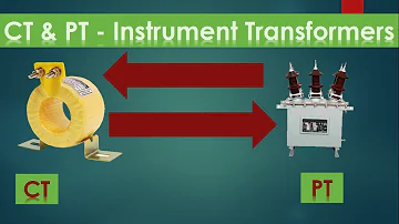
Transformers are divided into two types: voltage transformers and current transformers.
1) Voltage transformer (referred to as PT)
Convert high voltage to low voltage; the secondary winding's rated voltage is 100V, and it is connected in parallel with the measuring instrument's voltage coil and the relay protection device.
2) Current Transformer (CT for short)
Convert huge current to small current; the secondary winding's rated current is 5A or 1A, and it's connected in series with the measuring instrument's current coil and the replay protection mechanism.

Ⅴ. Precautions for the use of instrument transformers
Precautions for the use of voltage transformer
1) In addition to choosing the voltage transformer based on the measured voltage, be sure that the power utilized by the connected measuring meters and relays does not exceed the voltage transformer's rated capacity. Otherwise, the voltage transformer's precision will be compromised. The capacity matching to the accuracy is marked on the nameplate of the voltage transformer. The JDZ-10 voltage transformer, for example, has a capacity of 80VA at level 0.5, 100VA at level 1, and a maximum capacity of 500VA.

(2) Fuse should be installed in the primary and secondary coils of the voltage transformer for short-circuit prevention. The internal short-circuit fault of the voltage transformer and the short-circuit fault on the connecting line between the voltage transformer and the power grid are both protected by the fuse on the primary side of the voltage transformer. The fuse on the primary side of a 10kV voltage transformer has a rated current of 0.5A. The secondary side of the voltage transformer must not be short-circuited during operation, so a total fuse is installed on the secondary side's main circuit to protect the network from short-circuit faults below the total fuse; to prevent the short-circuit of the meter's voltage circuit, which affects the secondary main circuit's work, a fuse is also added to the meter circuit.The overall fuse's rated current is typically 3-5A, while the meter circuit's rated current is typically 1-2A. In most cases, the secondary outlet linked to an open triangle does not have a fuse. This is to avoid a lack of grounding signal and inadequate contact. It is difficult to monitor the fuse contact since there is no voltage at the open triangle's end.
(3) One end of the secondary side of the voltage transformer must be grounded to protect the safety of persons and equipment. The secondary circuit will be contacted if the secondary coil is not safely grounded, or if the insulation is destroyed and the high voltage escapes to the low voltage. It will be a life-or-death situation for the employees. Furthermore, the secondary circuit's insulation is inadequate. The insulation will be broken down and the voltage transformer will be more badly harmed if there is no grounding point.
(4)Check to see if the porcelain bottle is clean, if there are any fractures, faults, or discharge when inspecting the voltage transformer. whether the oil level in the oil-immersed voltage transformer is normal, and whether serious oil leakage or oil leakage exists; When the phases are grounded, listen to the voltage transformer for grounding monitoring to see if the sound is normal and if there is any strange odor.
Precautions for the use of current transformers
1) The primary winding of the current transformer should be connected in series with the circuit under test, while the secondary winding should be connected in series with all instrument loads, according to the series principle.

2)Otherwise, the inaccuracy will rise if the suitable transformation ratio is not chosen based on the measured current. Simultaneously, one end of the secondary side must be grounded to prevent the high voltage on the main side from accessing the secondary low voltage side once the insulation has been destroyed, resulting in personal and equipment injuries.
3) The secondary side must not open circuit because once it does, the primary side current I1 will all become magnetizing current, causing m and E2 to sharply increase, resulting in excessive saturation magnetization of the iron core, serious heat generation, and even coil burning;, which increases the error. The secondary side of the current transformer is utilized in series with current coils such as measuring devices and relays when it is in normal operation. Current coils, such as those found in measuring instruments and relays, have a very low impedance, and the secondary side is akin to a short circuit. Furthermore, the open circuit on the secondary side causes the voltage on the secondary side to reach several hundreds of volts, resulting in an electric shock if handled. As a result, a short-circuit switch is installed on the secondary side of the current transformer to prevent it from becoming open. Once the secondary side is open, remove the circuit load immediately, and then deal with the power outage. After everything is thrown away, it can be reused.
4)All circuits are installed in generators, transformers, outgoing lines, bus sectional circuit breakers, bus circuit breakers, bypass circuit breakers, and other circuits to meet the needs of measuring instruments, relay protection, circuit breaker failure judgment, and fault filtering, among other things. Secondary windings are used in 2 to 8 current transformers.
5) The protective current transformer should be installed as far away from the primary protection device as practicable to eliminate the non-protection zone. For example, if the site allows, two sets of current transformers should be placed on either side of the circuit breaker, putting the circuit breaker in cross protection. range
6) To avoid a busbar problem caused by the pillar-type current transformer's bushing flashover, the current transformer is normally installed at the circuit breaker or transformer's output.
 UTMEL
UTMEL
We are the professional distributor of electronic components, providing a large variety of products to save you a lot of time, effort, and cost with our efficient self-customized service. careful order preparation fast delivery service
1. What letter is used for instrument transformer?
There are two types of transformers: current transformers and voltage transformers. Current transformers start with L, voltage transformers start with J, Z means dry type, W means outdoor, these are universal, and then some other letters are related to the manufacturer's own serial number.
2. What is mutual inductance ratio?
The mutual inductance ratio of the transformer is generally called the transformation ratio, and the transformation ratio of the voltage transformer is equal to the rated voltage of the primary side divided by the rated voltage of the secondary side. The transformation ratio of the current transformer is equal to the primary rated current divided by the rated secondary current.
3. What is the accuracy of the instrument transformer?
It is used to measure the measurement error of the transformer. Generally, it is expressed by the accuracy level. For example, a 0.2-level current transformer means that the proportional error of the transformer is within the range of ±0.2% (at rated current), and the phase error is within ±10′. within the range.
 What is a Transformer: Definition, Principle and ApplicationsUTMEL03 November 20218367
Hi, fellas. I am Rose. Today I will introduce the transformer to you. The device that increases or decreases the voltage in an AC circuit is known as a transformer. The transformer is an AC voltage converter that works on the mutual inductance concept.
Read More LVDT - Linear Variable Differential Transformer BasicsUTMEL16 January 20219372
LVDT is the abbreviation of linear variable differential transformer, which belongs to linear displacement sensor. It is a movable iron core transformer that consists of a primary coil, two secondary coils, iron core, coil frame, shell and other components.
Read More Introduction to Flyback TransformerUTMEL29 January 202111826
As an energy conversion device that transfers energy from one part of the circuit to the other part at constant power, a flyback transformer can be described. Based on the application, the voltage is stepped up to a very high value in a flyback transformer. It is also called a transformer for line output, as the voltage of the output line is fed to the other part of the circuit. The primary winding of the transformer can be powered by a DC circuit with the assistance of the rectifying circuit.
Read More Audio Transformer-Types, Functions and WorkingUTMEL05 January 202615350
An audio transformer is an electromagnetic system designed to separate an input circuit from an output circuit and produce a signal that passes through it with filtering. A varying electromotive force (voltage) in the secondary winding linked to the other circuit is caused by this changing flux.
Read More Basics") RVDT(Rotary Variable Differential Transformer) BasicsUTMEL02 February 202120547
RVDT(Rotary Variable Differential Transformer) BasicsUTMEL02 February 202120547The Rotary Variable Differential Transformer or RVDT is regarded as the transformer that detects the angular displacement of the conductor. That is the kind of electromechanical transducer that gives the angular displacement of the input equal to the linear output.
Read More
Subscribe to Utmel !
![BLM18PG221SN1D]() BLM18PG221SN1D
BLM18PG221SN1DMurata Electronics
![RC0603JR-07100RL]() RC0603JR-07100RL
RC0603JR-07100RLYageo
![RC0603FR-071KL]() RC0603FR-071KL
RC0603FR-071KLYageo
![BLM18AG121SN1D]() BLM18AG121SN1D
BLM18AG121SN1DMurata Electronics
![AT25020B-SSHL-T]() AT25020B-SSHL-T
AT25020B-SSHL-TMicrochip Technology
![RC0805FR-071KL]() RC0805FR-071KL
RC0805FR-071KLYageo
![SN74LVC1G175DCKR]() SN74LVC1G175DCKR
SN74LVC1G175DCKRTexas Instruments
![BLM21AG102SN1D]() BLM21AG102SN1D
BLM21AG102SN1DMurata Electronics
![BLM18SG221TN1D]() BLM18SG221TN1D
BLM18SG221TN1DMurata Electronics
![FOD3120SD]() FOD3120SD
FOD3120SDON Semiconductor


